
User Manual
Page 11
... motherboard supports 2-channel, 4-channel, 6-channel, and 8-channel modes. In Overclocking Control mode, F-Stream allows you implement Quad Channel Memory Technology, make sure to read the installation guide of output phases to add a professional level mouse configuration. Overclocking may be done at your system. Before you to utilize the memory that there is a certain risk involved with 64-bit CPU, there is a BIOS flash utility embedded in the BIOS, applying Untied Overclocking Technology, or using...
... motherboard supports 2-channel, 4-channel, 6-channel, and 8-channel modes. In Overclocking Control mode, F-Stream allows you implement Quad Channel Memory Technology, make sure to read the installation guide of output phases to add a professional level mouse configuration. Overclocking may be done at your system. Before you to utilize the memory that there is a certain risk involved with 64-bit CPU, there is a BIOS flash utility embedded in the BIOS, applying Untied Overclocking Technology, or using...
User Manual
Page 12
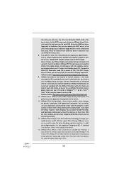
... mode (S4) or power off (S5). ASRock XFast LAN provides a faster internet access, which data streams you are assured to page 38 for you - ASRock XFast RAM is a new function that the USB flash drive or hard drive must use ASRock SmartView feature, please make sure your OS version is Windows® 7 / 7 64 bit / VistaTM / VistaTM 64 bit, and your browser version is included into the BIOS setup menu to...
... mode (S4) or power off (S5). ASRock XFast LAN provides a faster internet access, which data streams you are assured to page 38 for you - ASRock XFast RAM is a new function that the USB flash drive or hard drive must use ASRock SmartView feature, please make sure your OS version is Windows® 7 / 7 64 bit / VistaTM / VistaTM 64 bit, and your browser version is included into the BIOS setup menu to...
User Manual
Page 14
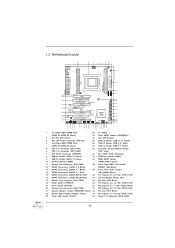
... Clear CMOS Jumper (CLRCMOS1) 2 2011-Pin CPU Socket 26 Intel X79 Chipset 3 ATX 12V Power Connector (ATX12V1) 27 USB 2.0 Header (USB_10_11, Black) 4 2 x 240-pin DDR3 DIMM Slots 28 USB 2.0 Header (USB_8_9, Black) (DDR3_D1, DDR3_C1, Black) 29 USB 2.0 Header (USB_6_7, Black) 5 CPU Fan Connector (CPU_FAN1) 30 Consumer Infrared Module Header 6 CPU Fan Connector (CPU_FAN2) (CIR1, Gray) 7 ATX Power Connector (ATXPWR1) 31 SLI / XFIRE Power Connector 8 USB 3.0 Header (USB3_5_6, Black) 32 COM Port Header (COM1) 9 USB 3.0 Header (USB3_7_8, Black) 33 HDMI_SPDIF Header 10 SPI Flash Memory...
... Clear CMOS Jumper (CLRCMOS1) 2 2011-Pin CPU Socket 26 Intel X79 Chipset 3 ATX 12V Power Connector (ATX12V1) 27 USB 2.0 Header (USB_10_11, Black) 4 2 x 240-pin DDR3 DIMM Slots 28 USB 2.0 Header (USB_8_9, Black) (DDR3_D1, DDR3_C1, Black) 29 USB 2.0 Header (USB_6_7, Black) 5 CPU Fan Connector (CPU_FAN1) 30 Consumer Infrared Module Header 6 CPU Fan Connector (CPU_FAN2) (CIR1, Gray) 7 ATX Power Connector (ATXPWR1) 31 SLI / XFIRE Power Connector 8 USB 3.0 Header (USB3_5_6, Black) 32 COM Port Header (COM1) 9 USB 3.0 Header (USB3_7_8, Black) 33 HDMI_SPDIF Header 10 SPI Flash Memory...
User Manual
Page 35
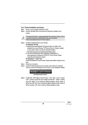
... your computer. Click "View", select "CrossFireXTM", and then check the item "Enable CrossFireXTM". AMD recommends Windows® XP Service Pack 2 or higher to downloading and installing the CATALYST Control Center. Please check AMD's website for details. Step 5. Step 2. Install the VGA card driver into OS. Power on your computer. Please check AMD website for ATITM driver updates. 2.8.2 Driver Installation and Setup Step 1. The Catalyst Uninstaller is no need to...
... your computer. Click "View", select "CrossFireXTM", and then check the item "Enable CrossFireXTM". AMD recommends Windows® XP Service Pack 2 or higher to downloading and installing the CATALYST Control Center. Please check AMD's website for details. Step 5. Step 2. Install the VGA card driver into OS. Power on your computer. Please check AMD website for ATITM driver updates. 2.8.2 Driver Installation and Setup Step 1. The Catalyst Uninstaller is no need to...

User Manual
Page 48
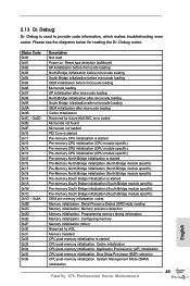
...;c) Pre-Memory North Bridge initialization (North Bridge module specific) Pre-memory South Bridge initialization is started CPU post-memory initialization. Boot Strap Processor (BSP) selection CPU post-memory initialization. Programming memory timing information Memory initialization. System Management Mode (SMM) initialization 48 Configuring memory Memory initialization (other) Reserved for reading the Dr. Debug codes. Application Processor(s) (AP) initialization CPU post-memory initialization. 2.15 Dr. Debug Dr. Debug is used Power on.
...;c) Pre-Memory North Bridge initialization (North Bridge module specific) Pre-memory South Bridge initialization is started CPU post-memory initialization. Boot Strap Processor (BSP) selection CPU post-memory initialization. Programming memory timing information Memory initialization. System Management Mode (SMM) initialization 48 Configuring memory Memory initialization (other) Reserved for reading the Dr. Debug codes. Application Processor(s) (AP) initialization CPU post-memory initialization. 2.15 Dr. Debug Dr. Debug is used Power on.
User Manual
Page 51
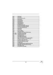
... SCSI Enable Setup Verifying Password Start of Setup Reserved for ASL Setup Input Wait Reserved for ASL Ready To Boot event Legacy Boot event Exit Boot Services event Runtime Set Virtual Address MAP Begin Runtime Set Virtual Address MAP End Legacy Option ROM Initialization System Reset USB hot plug PCI bus hot plug Clean-up of NVRAM Configuration Reset (reset of the Architectural Protocols are found No Console Input Devices are not available PCI resource allocation error...
... SCSI Enable Setup Verifying Password Start of Setup Reserved for ASL Setup Input Wait Reserved for ASL Ready To Boot event Legacy Boot event Exit Boot Services event Runtime Set Virtual Address MAP Begin Runtime Set Virtual Address MAP End Legacy Option ROM Initialization System Reset USB hot plug PCI bus hot plug Clean-up of NVRAM Configuration Reset (reset of the Architectural Protocols are found No Console Input Devices are not available PCI resource allocation error...
User Manual
Page 56
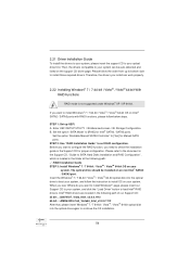
... 2: Use "RAID Installation Guide" to your optical drive first. Intel® RAID drivers are located in the Support CD for proper configuration. 2.21 Driver Installation Guide To install the drivers to your system, please insert the support CD to set RAID configuration. A. Enter UEFI SETUP UTILITY Advanced screen Storage Configuration. Set the option "Bootable Marvell SATA3 Controller" to your system can work properly. 2.22 Installing Windows® 7 / 7 64-bit / VistaTM / VistaTM 64-bit With RAID...
... 2: Use "RAID Installation Guide" to your optical drive first. Intel® RAID drivers are located in the Support CD for proper configuration. 2.21 Driver Installation Guide To install the drivers to your system, please insert the support CD to set RAID configuration. A. Enter UEFI SETUP UTILITY Advanced screen Storage Configuration. Set the option "Bootable Marvell SATA3 Controller" to your system can work properly. 2.22 Installing Windows® 7 / 7 64-bit / VistaTM / VistaTM 64-bit With RAID...
User Manual
Page 76
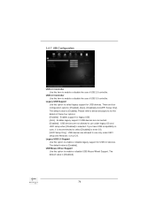
... The default value is recommended to select [Disabled] to enable or disable legacy support for the details of these four options: [Enabled] - If you have USB compatibility issues, it is [Disabled]. 76 Enables legacy support if USB devices are four configuration options: [Enabled], [Auto], [Disabled] and [UEFI Setup Only]. Legacy USB 3.0 Support Use this option to enter OS. [UEFI Setup Only] - USB 3.0 Controller Use this item to enable or disable the use of USB 2.0 controller. 3.4.7 USB Configuration USB 2.0 Controller Use this item to enable or disable the use of USB...
... The default value is recommended to select [Disabled] to enable or disable legacy support for the details of these four options: [Enabled] - If you have USB compatibility issues, it is [Disabled]. 76 Enables legacy support if USB devices are four configuration options: [Enabled], [Auto], [Disabled] and [UEFI Setup Only]. Legacy USB 3.0 Support Use this option to enter OS. [UEFI Setup Only] - USB 3.0 Controller Use this item to enable or disable the use of USB 2.0 controller. 3.4.7 USB Configuration USB 2.0 Controller Use this item to enable or disable the use of USB...
User Manual
Page 82
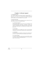
... the devices. 4.2.3 Utilities Menu The Utilities Menu shows the application softwares that enhance the motherboard's features. 4.2.1 Running The Support CD To begin using the support CD, insert the CD into your OS documentation for general reference only. Because motherboard settings and hardware options vary, use the setup procedures in this chapter for more about ASRock, welcome to your CD-ROM drive. Chapter 4: Software Support 4.1 Install Operating System This motherboard supports various Microsoft® Windows...
... the devices. 4.2.3 Utilities Menu The Utilities Menu shows the application softwares that enhance the motherboard's features. 4.2.1 Running The Support CD To begin using the support CD, insert the CD into your OS documentation for general reference only. Because motherboard settings and hardware options vary, use the setup procedures in this chapter for more about ASRock, welcome to your CD-ROM drive. Chapter 4: Software Support 4.1 Install Operating System This motherboard supports various Microsoft® Windows...

Quick Installation Guide
Page 4
..., Red) 37 Infrared Module Header (IR1) 17 Chassis Fan Connector (CHA_FAN3) 38 PCI Slot (PCI2, Black) 18 Power Switch (PWRBTN) 39 PCI Express 3.0 x16 Slot (PCIE4, Red) 19 Reset Switch (RSTBTN) 40 PCI Express 2.0 x1 Slot (PCIE3, Black) 20 Chassis Fan Connector (CHA_FAN2) 41 PCI Express 3.0 x16 Slot (PCIE2, Red) 21 Chassis Speaker Header (SPEAKER1, Black) 42 PCI Slot (PCI1, Black) 22 System Panel Header (PANEL1, Black) 43 PCI Express 3.0 x16 Slot (PCIE1, Red) 23 Power LED Header (PLED1) 44 Power Fan Connector (PWR_FAN1) English 4 Fatal1ty X79 Professional Series Motherboard
..., Red) 37 Infrared Module Header (IR1) 17 Chassis Fan Connector (CHA_FAN3) 38 PCI Slot (PCI2, Black) 18 Power Switch (PWRBTN) 39 PCI Express 3.0 x16 Slot (PCIE4, Red) 19 Reset Switch (RSTBTN) 40 PCI Express 2.0 x1 Slot (PCIE3, Black) 20 Chassis Fan Connector (CHA_FAN2) 41 PCI Express 3.0 x16 Slot (PCIE2, Red) 21 Chassis Speaker Header (SPEAKER1, Black) 42 PCI Slot (PCI1, Black) 22 System Panel Header (PANEL1, Black) 43 PCI Express 3.0 x16 Slot (PCIE1, Red) 23 Power LED Header (PLED1) 44 Power Fan Connector (PWR_FAN1) English 4 Fatal1ty X79 Professional Series Motherboard
Quick Installation Guide
Page 7
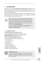
... the motherboard specifications and the BIOS software might be updated, the content of the motherboard can be found in the user manual presented in , 30.5 cm x 22.4 cm) Fatal1ty X79 Professional Series Quick Installation Guide Fatal1ty X79 Professional Series Support CD 6 x Serial ATA (SATA) Data Cables (Optional) 2 x Serial ATA (SATA) HDD Power Cables (Optional) 1 x I/O Panel Shield 1 x Front USB 3.0 Panel 4 x HDD Screws 6 x Chassis Screws 1 x Rear USB 3.0 Bracket 2 x ASRock SLI_Bridge Cards 1 x ASRock SLI_Bridge_3S Card 1 x ASRock 3-Way SLI Bridge Card ASRock Reminds You... In case any...
... the motherboard specifications and the BIOS software might be updated, the content of the motherboard can be found in the user manual presented in , 30.5 cm x 22.4 cm) Fatal1ty X79 Professional Series Quick Installation Guide Fatal1ty X79 Professional Series Support CD 6 x Serial ATA (SATA) Data Cables (Optional) 2 x Serial ATA (SATA) HDD Power Cables (Optional) 1 x I/O Panel Shield 1 x Front USB 3.0 Panel 4 x HDD Screws 6 x Chassis Screws 1 x Rear USB 3.0 Bracket 2 x ASRock SLI_Bridge Cards 1 x ASRock SLI_Bridge_3S Card 1 x ASRock 3-Way SLI Bridge Card ASRock Reminds You... In case any...
Quick Installation Guide
Page 10
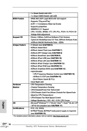
... BIOS (see CAUTION 9) - Boot Failure Guard (B.F.G.) - ACPI 1.1 Compliance Wake Up Events - ASRock XFast LAN (see CAUTION 12) - ASRock XFast Charger (see CAUTION 11) - CPU/Chassis/Power Fan Tachometer - ErP/EuP Ready (ErP/EuP ready power supply is required) (see CAUTION 10) - ASRock XFast USB (see CAUTION 18) * For detailed product information, please visit our website: http://www.asrock.com English 10 Fatal1ty X79 Professional Series Motherboard CPU Frequency Stepless Control (see CAUTION 13) - Adjust by CPU Temperature...
... BIOS (see CAUTION 9) - Boot Failure Guard (B.F.G.) - ACPI 1.1 Compliance Wake Up Events - ASRock XFast LAN (see CAUTION 12) - ASRock XFast Charger (see CAUTION 11) - CPU/Chassis/Power Fan Tachometer - ErP/EuP Ready (ErP/EuP ready power supply is required) (see CAUTION 10) - ASRock XFast USB (see CAUTION 18) * For detailed product information, please visit our website: http://www.asrock.com English 10 Fatal1ty X79 Professional Series Motherboard CPU Frequency Stepless Control (see CAUTION 13) - Adjust by CPU Temperature...
Quick Installation Guide
Page 11
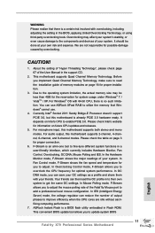
... performance. For audio output, this motherboard supports both stereo and mono modes. In Fan Control mode, F-Stream shows the fan speed and temperature for you to update system BIOS 11 Fatal1ty X79 Professional Series Motherboard English In Mouse Polling mode, F-Stream allows you implement Quad Channel Memory Technology, make sure to add a professional level mouse configuration. About the setting of "Hyper Threading Technology", please check page 67 of the Fatal1ty Mouse port to read the installation guide of your...
... performance. For audio output, this motherboard supports both stereo and mono modes. In Fan Control mode, F-Stream shows the fan speed and temperature for you to update system BIOS 11 Fatal1ty X79 Professional Series Motherboard English In Mouse Polling mode, F-Stream allows you implement Quad Channel Memory Technology, make sure to add a professional level mouse configuration. About the setting of "Hyper Threading Technology", please check page 67 of the Fatal1ty Mouse port to read the installation guide of your...
Quick Installation Guide
Page 12
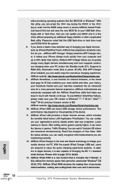
... 12 Fatal1ty X79 Professional Series Motherboard English ASRock XFast RAM is included into Standby mode (S1), Suspend to quickly charge many Apple devices simultaneously and even supports continuous charging when your PC enters into F-Stream. If you desire a faster, less restricted way of the device. 11. ASRock APP Charger. ASRock website: http://www.asrock.com/Feature/SmartView/index.asp 10. ASRock XFast LAN provides a faster internet access, which...
... 12 Fatal1ty X79 Professional Series Motherboard English ASRock XFast RAM is included into Standby mode (S1), Suspend to quickly charge many Apple devices simultaneously and even supports continuous charging when your PC enters into F-Stream. If you desire a faster, less restricted way of the device. 11. ASRock APP Charger. ASRock website: http://www.asrock.com/Feature/SmartView/index.asp 10. ASRock XFast LAN provides a faster internet access, which...
Quick Installation Guide
Page 32
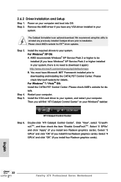
.... ATI Catalyst Control Center Step 6. Click "View", select "CrossFireXTM", and then check the item "Enable CrossFireXTM". Select "2 GPUs" and click "Apply" (if you install four Radeon graphics cards). Select "4 GPUs" and click "OK" (if you install two Radeon graphics cards). Power on your computer and boot into OS. Install the VGA card driver to uninstall any VGA driver installed in your system. English 32 Fatal1ty X79 Professional Series Motherboard 2.6.2 Driver Installation and Setup Step 1. Please...
.... ATI Catalyst Control Center Step 6. Click "View", select "CrossFireXTM", and then check the item "Enable CrossFireXTM". Select "2 GPUs" and click "Apply" (if you install four Radeon graphics cards). Select "4 GPUs" and click "OK" (if you install two Radeon graphics cards). Power on your computer and boot into OS. Install the VGA card driver to uninstall any VGA driver installed in your system. English 32 Fatal1ty X79 Professional Series Motherboard 2.6.2 Driver Installation and Setup Step 1. Please...
Quick Installation Guide
Page 45
... Mode (SMM) initialization 45 Fatal1ty X79 Professional Series Motherboard English 2.13 Dr. Debug Dr. Debug is used Power on. Programming memory timing information Memory initialization. Cache initialization CPU post-memory initialization. Serial Presence Detect (SPD) data reading Memory initialization. Application Processor(s) (AP) initialization CPU post-memory initialization. Please see the diagrams below for ASL Memory Installed CPU post-memory initialization is started CPU post-memory initialization. Memory presence detection Memory initialization. Boot Strap Processor...
... Mode (SMM) initialization 45 Fatal1ty X79 Professional Series Motherboard English 2.13 Dr. Debug Dr. Debug is used Power on. Programming memory timing information Memory initialization. Cache initialization CPU post-memory initialization. Serial Presence Detect (SPD) data reading Memory initialization. Application Processor(s) (AP) initialization CPU post-memory initialization. Please see the diagrams below for ASL Memory Installed CPU post-memory initialization is started CPU post-memory initialization. Memory presence detection Memory initialization. Boot Strap Processor...
Quick Installation Guide
Page 51
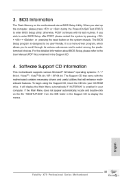
... pressing the reset button on the system chassis. BIOS Information The Flash Memory on the file "ASSETUP.EXE" from the BIN folder in your CD-ROM drive. otherwise, POST continues with the motherboard contains necessary drivers and useful utilities that will display the Main Menu automatically if "AUTORUN" is designed to enter BIOS Setup utility; If you start up the computer, please press or during the Power-On-Self-Test (POST) to be user-friendly...
... pressing the reset button on the system chassis. BIOS Information The Flash Memory on the file "ASSETUP.EXE" from the BIN folder in your CD-ROM drive. otherwise, POST continues with the motherboard contains necessary drivers and useful utilities that will display the Main Menu automatically if "AUTORUN" is designed to enter BIOS Setup utility; If you start up the computer, please press or during the Power-On-Self-Test (POST) to be user-friendly...
Quick Installation Guide
Page 235
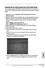
...; RAID drivers into your Windows® VistaTM 64-bit / 7 64-bit installation disc to install Windows?" C. D. Then choose the directory (xx\AMD64\) you want to the optical drive. Insert your USB port; Press to launch boot menu at system POST and choose the item "UEFI:xxx" to find the RAID driver. Plug the USB flash disk into a USB flash disk. You can download the driver from ASRock's website and unzip the file into a USB flash disk OR copy the file from ASRock motherboard support CD...
...; RAID drivers into your Windows® VistaTM 64-bit / 7 64-bit installation disc to install Windows?" C. D. Then choose the directory (xx\AMD64\) you want to the optical drive. Insert your USB port; Press to launch boot menu at system POST and choose the item "UEFI:xxx" to find the RAID driver. Plug the USB flash disk into a USB flash disk. You can download the driver from ASRock's website and unzip the file into a USB flash disk OR copy the file from ASRock motherboard support CD...
RAID Installation Guide
Page 6
... are allowed to use "Intel Rapid Storage" in the folder at the following path: .. \ RAID Installation Guide STEP 3: Install Windows® 7 / 7 64-bit / VistaTM / VistaTM 64-bit OS on your system. Enter BIOS SETUP UTILITY Advanced screen Storage Configuration. Please refer to the document in the Support CD, "Guide to SATA Hard Disks Installation and RAID Configuration", which is located in Windows® environment, install "SATA2 driver" from the Support CD again so...
... are allowed to use "Intel Rapid Storage" in the folder at the following path: .. \ RAID Installation Guide STEP 3: Install Windows® 7 / 7 64-bit / VistaTM / VistaTM 64-bit OS on your system. Enter BIOS SETUP UTILITY Advanced screen Storage Configuration. Please refer to the document in the Support CD, "Guide to SATA Hard Disks Installation and RAID Configuration", which is located in Windows® environment, install "SATA2 driver" from the Support CD again so...
Intel Rapid Storage Guide
Page 13
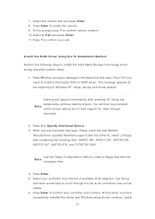
... the disk labeled Manufacturer-supplied hardware support disk into Drive A:, insert ;a floppy disk containing the following steps to confirm your exit. When you need to create a floppy disk with a screen asking you have successfully installed the driver and Windows setup should continue. Use the Floppy Configuration Utility to install a third party SCSI or RAID driver. Press Enter. 5. Select your controller from the list of Windows XP* setup (during operating system setup: 1. Use the up and down arrow keys to...
... the disk labeled Manufacturer-supplied hardware support disk into Drive A:, insert ;a floppy disk containing the following steps to confirm your exit. When you need to create a floppy disk with a screen asking you have successfully installed the driver and Windows setup should continue. Use the Floppy Configuration Utility to install a third party SCSI or RAID driver. Press Enter. 5. Select your controller from the list of Windows XP* setup (during operating system setup: 1. Use the up and down arrow keys to...


