User Manual
Page 4
...complies with Part 15 of merchantability or fitness for a particular purpose. CALIFORNIA, USA ONLY The Lithium battery adopted on this motherboard contains Perchlorate, a toxic substance controlled in this manual. Products and corporate names appearing in this manual may or may not be ...change without notice, and should not be constructed as a commitment by the purchaser for backup purpose, without intent to infringe. ASRock assumes no event shall ASRock, its directors, officers, employees, or agents be liable for any indirect, special, incidental, or consequential damages ...
...complies with Part 15 of merchantability or fitness for a particular purpose. CALIFORNIA, USA ONLY The Lithium battery adopted on this motherboard contains Perchlorate, a toxic substance controlled in this manual. Products and corporate names appearing in this manual may or may not be ...change without notice, and should not be constructed as a commitment by the purchaser for backup purpose, without intent to infringe. ASRock assumes no event shall ASRock, its directors, officers, employees, or agents be liable for any indirect, special, incidental, or consequential damages ...
User Manual
Page 5
Contents 1 Introduction 7 1.1 Package Contents 7 1.2 Specifications 8 1.3 Motherboard Layout 14 1.4 I/O Panel 15 2 Installation 17 2.1 Screw Holes 17 2.2 Pre-installation Precautions 17 2.3 CPU Installation 18 2.4 Installation of Heatsink and CPU... Guide 24 2.8 CrossFireXTM, 3-Way CrossFireXTM, 4-Way CrossFireXTM and Quad CrossFireXTM Operation Guide 31 2.9 Surround Display Features 36 2.10 ASRock Smart Remote Installation Guide 37 2.11 ASRock XFast Charger Operation Guide 38 2.12 Jumpers Setup 39 2.13 Onboard Headers and Connectors 40 2.14 Smart Switches 47 2.15 Dr...
Contents 1 Introduction 7 1.1 Package Contents 7 1.2 Specifications 8 1.3 Motherboard Layout 14 1.4 I/O Panel 15 2 Installation 17 2.1 Screw Holes 17 2.2 Pre-installation Precautions 17 2.3 CPU Installation 18 2.4 Installation of Heatsink and CPU... Guide 24 2.8 CrossFireXTM, 3-Way CrossFireXTM, 4-Way CrossFireXTM and Quad CrossFireXTM Operation Guide 31 2.9 Surround Display Features 36 2.10 ASRock Smart Remote Installation Guide 37 2.11 ASRock XFast Charger Operation Guide 38 2.12 Jumpers Setup 39 2.13 Onboard Headers and Connectors 40 2.14 Smart Switches 47 2.15 Dr...
User Manual
Page 7
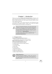
... the BIOS setup, please refer to AHCI mode. www.asrock.com/support/index.asp 1.1 Package Contents Fatal1ty X79 Professional Series Motherboard (ATX Form Factor: 12.0-in x 9.6-in Storage Configuration to the "User Manual" in our support CD for purchasing Fatal1ty X79 Professional Series motherboard, a reliable motherboard produced under ASRock's consistently stringent quality control. It delivers excellent performance with robust...
... the BIOS setup, please refer to AHCI mode. www.asrock.com/support/index.asp 1.1 Package Contents Fatal1ty X79 Professional Series Motherboard (ATX Form Factor: 12.0-in x 9.6-in Storage Configuration to the "User Manual" in our support CD for purchasing Fatal1ty X79 Professional Series motherboard, a reliable motherboard produced under ASRock's consistently stringent quality control. It delivers excellent performance with robust...

User Manual
Page 11
...About the setting of your system's stability, or even cause damage to the components and devices of the Fatal1ty Mouse port to overclock the CPU frequency for system usage under Windows® 7 / VistaTM / XP...to get the same OC settings. It depends on page 21 for you to add a professional level mouse configuration. Overclocking may be done at your own risk and expense. ... performance. For microphone input, this motherboard supports both stereo and mono modes. In Overclocking Control mode, F-Stream allows you to adjust. ASRock Instant Flash is no such limitation.
...About the setting of your system's stability, or even cause damage to the components and devices of the Fatal1ty Mouse port to overclock the CPU frequency for system usage under Windows® 7 / VistaTM / XP...to get the same OC settings. It depends on page 21 for you to add a professional level mouse configuration. Overclocking may be done at your own risk and expense. ... performance. For microphone input, this motherboard supports both stereo and mono modes. In Overclocking Control mode, F-Stream allows you to adjust. ASRock Instant Flash is no such limitation.
User Manual
Page 12
... add new programs. Lower Latency in a few clicks without preparing an additional floppy diskette or other complicated flash utility. ASRock XFast RAM shortens the loading time of the device. 11. Traffic Shaping: You can update your browser version is the best ... feature, please make sure your OS version is also capable of Adobe Photoshop 5 times 12 ASRock website: http://www.asrock.com/Feature/SmartView/index.asp 10. ASRock motherboards are exclusively equipped with friends on the properties of previously visited websites, making web surfing faster than ...
... add new programs. Lower Latency in a few clicks without preparing an additional floppy diskette or other complicated flash utility. ASRock XFast RAM shortens the loading time of the device. 11. Traffic Shaping: You can update your browser version is the best ... feature, please make sure your OS version is also capable of Adobe Photoshop 5 times 12 ASRock website: http://www.asrock.com/Feature/SmartView/index.asp 10. ASRock motherboards are exclusively equipped with friends on the properties of previously visited websites, making web surfing faster than ...
User Manual
Page 13
...suggestion, the EuP ready power supply must meet EuP standards, an EuP ready motherboard and an EuP ready power supply are not supported by the European Union to update their lifespan. 14. ASRock Crashless BIOS allows users to define the power consumption for more details. 13...recommended CPU bus frequencies may cause instability of your USB disk. faster. Only USB2.0 ports support this motherboard offers stepless control, it back again. Another advantage of ASRock XFast RAM is that BIOS files need to perform over-clocking. Intel Rapid Storage Technology enterprise 3.0...
...suggestion, the EuP ready power supply must meet EuP standards, an EuP ready motherboard and an EuP ready power supply are not supported by the European Union to update their lifespan. 14. ASRock Crashless BIOS allows users to define the power consumption for more details. 13...recommended CPU bus frequencies may cause instability of your USB disk. faster. Only USB2.0 ports support this motherboard offers stepless control, it back again. Another advantage of ASRock XFast RAM is that BIOS files need to perform over-clocking. Intel Rapid Storage Technology enterprise 3.0...
User Manual
Page 14
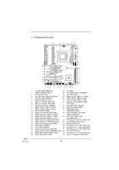
1.3 Motherboard Layout 1 USB 2.0 T: USB0 B: USB1 PS2 Keyboard Clr CMOS Optical Coaxial SPDIF SPDIF USB 3.0 T: USB1 ... USB3_7_8 1 Top: LINE IN Center: FRONT Bottom: MIC IN 9 44 43 PCIE1 X79 Professional 64Mb BIOS 10 42 PCI1 11 SATA2_2_3 CHA_FAN1 FATAL1TY SATA3 6Gb/s 12 41 PCIE2 LAN SATA2_0_1 PHY 2 oz Copper PCB 1394a 13 CMOS 40... DDR3 DIMM Slots 24 Dr. Debug (DDR3_A1, DDR3_B1, Black) 25 Clear CMOS Jumper (CLRCMOS1) 2 2011-Pin CPU Socket 26 Intel X79 Chipset 3 ATX 12V Power Connector (ATX12V1) 27 USB 2.0 Header (USB_10_11, Black) 4 2 x 240-pin DDR3 DIMM Slots 28 USB...
1.3 Motherboard Layout 1 USB 2.0 T: USB0 B: USB1 PS2 Keyboard Clr CMOS Optical Coaxial SPDIF SPDIF USB 3.0 T: USB1 ... USB3_7_8 1 Top: LINE IN Center: FRONT Bottom: MIC IN 9 44 43 PCIE1 X79 Professional 64Mb BIOS 10 42 PCI1 11 SATA2_2_3 CHA_FAN1 FATAL1TY SATA3 6Gb/s 12 41 PCIE2 LAN SATA2_0_1 PHY 2 oz Copper PCB 1394a 13 CMOS 40... DDR3 DIMM Slots 24 Dr. Debug (DDR3_A1, DDR3_B1, Black) 25 Clear CMOS Jumper (CLRCMOS1) 2 2011-Pin CPU Socket 26 Intel X79 Chipset 3 ATX 12V Power Connector (ATX12V1) 27 USB 2.0 Header (USB_10_11, Black) 4 2 x 240-pin DDR3 DIMM Slots 28 USB...
User Manual
Page 17
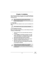
...-tighten the screws! Whenever you install or remove any motherboard settings. 1. board to the chassis, please do so may damage the motherboard. 2.2 Pre-installation Precautions Take note of your motherboard directly on a grounded anti- Before you install motherboard components or change any component, ensure that the power is...screws into it on the carpet or the like. Doing so may cause physical injuries to secure the mother- Failure to the motherboard, peripherals, and/or components. 17 Doing so may cause severe damage to do not over -tighten the screws! Make sure to...
...-tighten the screws! Whenever you install or remove any motherboard settings. 1. board to the chassis, please do so may damage the motherboard. 2.2 Pre-installation Precautions Take note of your motherboard directly on a grounded anti- Before you install motherboard components or change any component, ensure that the power is...screws into it on the carpet or the like. Doing so may cause physical injuries to secure the mother- Failure to the motherboard, peripherals, and/or components. 17 Doing so may cause severe damage to do not over -tighten the screws! Make sure to...
User Manual
Page 19
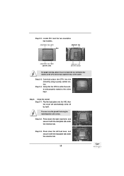
Locate Pin1 and the two orientation key notches. Carefully place the CPU into the socket by itself. The cover must be placed if returning the motherboard for after service. Step 3-2. Press down the right load lever, and secure it with the load plate tab under the retention tab. 19 Flip the ...
Locate Pin1 and the two orientation key notches. Carefully place the CPU into the socket by itself. The cover must be placed if returning the motherboard for after service. Step 3-2. Press down the right load lever, and secure it with the load plate tab under the retention tab. 19 Flip the ...
User Manual
Page 20
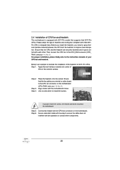
...with each other components. 20 Ensure that the CPU and the heatsink are oriented on side closest to the CPU fan connector on the motherboard. Step 2. If you need to spray thermal interface material between the CPU and the heatsink to improve heat dissipation. Step 6. For ... the screws, the heatsink cannot be secured on the socket's surface. Step 5. Step 4. Step 1. 2.4 Installation of CPU Fan and Heatsink This motherboard is an example to illustrate the installation of the heatsink for 2011-Pin CPUs. Use a screw driver to the instruction manuals of your CPU fan...
...with each other components. 20 Ensure that the CPU and the heatsink are oriented on side closest to the CPU fan connector on the motherboard. Step 2. If you need to spray thermal interface material between the CPU and the heatsink to improve heat dissipation. Step 6. For ... the screws, the heatsink cannot be secured on the socket's surface. Step 5. Step 4. Step 1. 2.4 Installation of CPU Fan and Heatsink This motherboard is an example to illustrate the installation of the heatsink for 2011-Pin CPUs. Use a screw driver to the instruction manuals of your CPU fan...
User Manual
Page 21
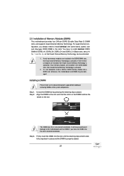
... DIMM on the slot. It will cause permanent damage to install a DDR or DDR2 memory module into a DDR3 slot; 2.5 Installation of Memory Modules (DIMM) This motherboard provides four 240-pin DDR3 (Double Data Rate 3) DIMM slots, and supports Quad Channel Memory Technology. Unlock the DIMM slot by pressing the retaining clips... always need to install identical (the same brand, speed, size and chip-type) DDR3 DIMM in place and the DIMM is not allowed to the motherboard and the DIMM if you force the DIMM into the slot until the retaining clips at both ends fully snap back in the slots: You...
... DIMM on the slot. It will cause permanent damage to install a DDR or DDR2 memory module into a DDR3 slot; 2.5 Installation of Memory Modules (DIMM) This motherboard provides four 240-pin DDR3 (Double Data Rate 3) DIMM slots, and supports Quad Channel Memory Technology. Unlock the DIMM slot by pressing the retaining clips... always need to install identical (the same brand, speed, size and chip-type) DDR3 DIMM in place and the DIMM is not allowed to the motherboard and the DIMM if you force the DIMM into the slot until the retaining clips at both ends fully snap back in the slots: You...
User Manual
Page 22
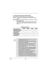
... will work at x16 bandwidth, while PCIE2 works at x16 bandwidth. 3. Currently Intel® Socket 2011 Sandy Bridge-E Processor doesn't support PCIE 3.0, but this motherboard. Such as ASRock Game Blaster, Gigabit LAN card or SATA2 cards, etc. Therefore, both these two slots will work at x8 bandwidth. 4. PCIE slots:PCIE1 / PCIE2 / PCIE4...
... will work at x16 bandwidth, while PCIE2 works at x16 bandwidth. 3. Currently Intel® Socket 2011 Sandy Bridge-E Processor doesn't support PCIE 3.0, but this motherboard. Such as ASRock Game Blaster, Gigabit LAN card or SATA2 cards, etc. Therefore, both these two slots will work at x8 bandwidth. 4. PCIE slots:PCIE1 / PCIE2 / PCIE4...
User Manual
Page 23
Remove the system unit cover (if your motherboard is unplugged. Step 5. Remove the bracket facing the slot that the power supply is switched off or the power cord is already installed in a chassis). ...
Remove the system unit cover (if your motherboard is unplugged. Step 5. Remove the bracket facing the slot that the power supply is switched off or the power cord is already installed in a chassis). ...
User Manual
Page 24
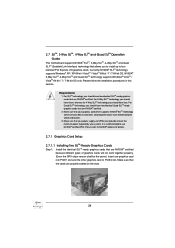
... in this section. For Quad SLITM technology, you to install up to PCIE4 slot. 2.7 SLITM, 3-Way SLITM, 4-Way SLITM and Quad SLITM Operation Guide This motherboard supports NVIDIA® SLITM, 3-Way SLITM, 4-Way SLITM and Quad SLITM (Scalable Link Interface) technology that your system. Make sure that are NVIDIA® certi...
... in this section. For Quad SLITM technology, you to install up to PCIE4 slot. 2.7 SLITM, 3-Way SLITM, 4-Way SLITM and Quad SLITM Operation Guide This motherboard supports NVIDIA® SLITM, 3-Way SLITM, 4-Way SLITM and Quad SLITM (Scalable Link Interface) technology that your system. Make sure that are NVIDIA® certi...
User Manual
Page 31
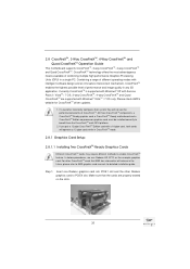
... with Windows® VistaTM / 7 OS only. 2.8 CrossFireXTM, 3-Way CrossFireXTM, 4-Way CrossFireXTM and Quad CrossFireXTM Operation Guide This motherboard supports CrossFireXTM, 3-way CrossFireXTM, 4-way CrossFireXTM and Quad CrossFireXTM. Combining a range of performance and image quality in the future, ...system they will operate as the example graphics card. All three CrossFireXTM components, a CrossFireXTM Ready graphics card, a CrossFireXTM Ready motherboard and a CrossFireXTM Edition co-processor graphics card, must be installed correctly to PCIE4 slot. If you pair a 12-pipe ...
... with Windows® VistaTM / 7 OS only. 2.8 CrossFireXTM, 3-Way CrossFireXTM, 4-Way CrossFireXTM and Quad CrossFireXTM Operation Guide This motherboard supports CrossFireXTM, 3-way CrossFireXTM, 4-way CrossFireXTM and Quad CrossFireXTM. Combining a range of performance and image quality in the future, ...system they will operate as the example graphics card. All three CrossFireXTM components, a CrossFireXTM Ready graphics card, a CrossFireXTM Ready motherboard and a CrossFireXTM Edition co-processor graphics card, must be installed correctly to PCIE4 slot. If you pair a 12-pipe ...
User Manual
Page 32
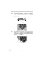
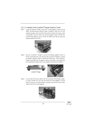
... graphics card on the top of the Radeon graphics cards. (The CrossFire Bridge is provided with the graphics card you purchase, not bundled with this motherboard. Please refer to D-Sub adapter.) 32 Connect two Radeon graphics cards by installing a CrossFire Bridge on the CrossFire Bridge Interconnects on PCIE1 slot. (You may...
... graphics card on the top of the Radeon graphics cards. (The CrossFire Bridge is provided with the graphics card you purchase, not bundled with this motherboard. Please refer to D-Sub adapter.) 32 Connect two Radeon graphics cards by installing a CrossFire Bridge on the CrossFire Bridge Interconnects on PCIE1 slot. (You may...
User Manual
Page 33
... connect the Radeon graphics cards on PCIE2 and PCIE4 slots. (The CrossFireTM Bridge is provided with the graphics card you purchase, not bundled with this motherboard. Connect the DVI monitor cable to the DVI connector on the Radeon graphics card on PCIE1 slot. (You may use the other graphics card to...
... connect the Radeon graphics cards on PCIE2 and PCIE4 slots. (The CrossFireTM Bridge is provided with the graphics card you purchase, not bundled with this motherboard. Connect the DVI monitor cable to the DVI connector on the Radeon graphics card on PCIE1 slot. (You may use the other graphics card to...
User Manual
Page 34
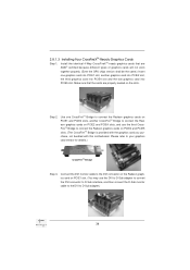
... connect the Radeon graphics cards on PCIE4 and PCIE5 slots. (The CrossFireTM Bridge is provided with the graphics card you purchase, not bundled with this motherboard. 2.8.1.3 Installing Four CrossFireXTM-Ready Graphics Cards Step 1. Use one graphics card into PCIE1 slot, another CrossFireTM Bridge to connect the Radeon graphics cards on PCIE2...
... connect the Radeon graphics cards on PCIE4 and PCIE5 slots. (The CrossFireTM Bridge is provided with the graphics card you purchase, not bundled with this motherboard. 2.8.1.3 Installing Four CrossFireXTM-Ready Graphics Cards Step 1. Use one graphics card into PCIE1 slot, another CrossFireTM Bridge to connect the Radeon graphics cards on PCIE2...
User Manual
Page 36
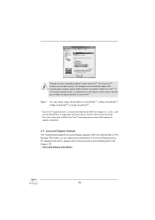
...;t, without intent to the document at the following path in "ATI Catalyst Control Center" is used only for updates and details. 2.9 Surround Display Feature This motherboard supports Surround Display upgrade. For detailed instructions, please refer to infringe. * For further information of CrossFireXTM. Your computer will automatically reboot. Although you have selected...
...;t, without intent to the document at the following path in "ATI Catalyst Control Center" is used only for updates and details. 2.9 Surround Display Feature This motherboard supports Surround Display upgrade. For detailed instructions, please refer to infringe. * For further information of CrossFireXTM. Your computer will automatically reboot. Although you have selected...
User Manual
Page 37
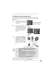
...does not support Hot-Plug function. Step1. GND IRTX IRRX ATX+5VSB Install Multi-Angle CIR Receiver to ASRock website for the motherboard support list: http://www.asrock.com 37 Please install it on the market. 3. Connect the front USB cable to connect it before ... function. Please refer to the front USB port. Only one of ASRock motherboards. Step3. Multi-Angle CIR Receiver is used for ASRock motherboard with most of the chassis on the rear panel. Please refer to the USB 2.0 header on ASRock motherboard. USB 2.0 header (9-pin, black) CIR header (4-pin, gray...
...does not support Hot-Plug function. Step1. GND IRTX IRRX ATX+5VSB Install Multi-Angle CIR Receiver to ASRock website for the motherboard support list: http://www.asrock.com 37 Please install it on the market. 3. Connect the front USB cable to connect it before ... function. Please refer to the front USB port. Only one of ASRock motherboards. Step3. Multi-Angle CIR Receiver is used for ASRock motherboard with most of the chassis on the rear panel. Please refer to the USB 2.0 header on ASRock motherboard. USB 2.0 header (9-pin, black) CIR header (4-pin, gray...

