
User Manual
Page 8
...1000 Mb/s - Supports Wake-On-LAN - quality Conductive Polymer Capacitors) - Supports Intel® CoreTM i7 processor family for the LGA 2011 Socket - Supports THX TruStudioTM - Supports Hyper-Threading Technology (see CAUTION 4) - 1 x PCI Express 2.0 x 1 slot - 2 x...PCI slots - Supports Energy Efficient Ethernet 802.3az - Quad Channel DDR3 Memory Technology (see CAUTION 3) - Supports PXE I /O - Intel® X79 - Broadcom BCM57781 - Supports Intel® Turbo Boost 2.0 Technology - capacity of system memory: 32GB (see CAUTION 2) - 4 x DDR3 DIMM slots - Supports...
...1000 Mb/s - Supports Wake-On-LAN - quality Conductive Polymer Capacitors) - Supports Intel® CoreTM i7 processor family for the LGA 2011 Socket - Supports THX TruStudioTM - Supports Hyper-Threading Technology (see CAUTION 4) - 1 x PCI Express 2.0 x 1 slot - 2 x...PCI slots - Supports Energy Efficient Ethernet 802.3az - Quad Channel DDR3 Memory Technology (see CAUTION 3) - Supports PXE I /O - Intel® X79 - Broadcom BCM57781 - Supports Intel® Turbo Boost 2.0 Technology - capacity of system memory: 32GB (see CAUTION 2) - 4 x DDR3 DIMM slots - Supports...

User Manual
Page 11
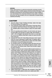
...Quad Channel Memory Technology, make sure to read the installation guide of the Fatal1ty Mouse port to add a professional level mouse configuration. Before you to the components and devices of ... the fan speed and temperature for proper connection. 6. Your friends can use . 4. ASRock Instant Flash is a BIOS flash utility embedded in to their own system to adjust. WARNING ... Control mode, F-Stream allows you to get the same OC settings. Currently Intel® Socket 2011 Sandy Bridge-E Processor doesn't support PCIE 3.0, but this motherboard is an all-in-one ...
...Quad Channel Memory Technology, make sure to read the installation guide of the Fatal1ty Mouse port to add a professional level mouse configuration. Before you to the components and devices of ... the fan speed and temperature for proper connection. 6. Your friends can use . 4. ASRock Instant Flash is a BIOS flash utility embedded in to their own system to adjust. WARNING ... Control mode, F-Stream allows you to get the same OC settings. Currently Intel® Socket 2011 Sandy Bridge-E Processor doesn't support PCIE 3.0, but this motherboard is an all-in-one ...
User Manual
Page 14
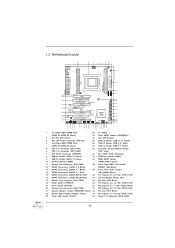
... CTR BASS 8 PWR_FAN1 USB3_5_6 1 USB3_7_8 1 Top: LINE IN Center: FRONT Bottom: MIC IN 9 44 43 PCIE1 X79 Professional 64Mb BIOS 10 42 PCI1 11 SATA2_2_3 CHA_FAN1 FATAL1TY SATA3 6Gb/s 12 41 PCIE2 LAN SATA2_0_1 PHY 2 oz Copper PCB 1394a 13 CMOS 40 PCIE3 Battery SATA3_0_1 Super I/O ...24 23 22 21 20 1 2 x 240-pin DDR3 DIMM Slots 24 Dr. Debug (DDR3_A1, DDR3_B1, Black) 25 Clear CMOS Jumper (CLRCMOS1) 2 2011-Pin CPU Socket 26 Intel X79 Chipset 3 ATX 12V Power Connector (ATX12V1) 27 USB 2.0 Header (USB_10_11, Black) 4 2 x 240-pin DDR3 DIMM Slots 28 USB 2.0 Header (...
... CTR BASS 8 PWR_FAN1 USB3_5_6 1 USB3_7_8 1 Top: LINE IN Center: FRONT Bottom: MIC IN 9 44 43 PCIE1 X79 Professional 64Mb BIOS 10 42 PCI1 11 SATA2_2_3 CHA_FAN1 FATAL1TY SATA3 6Gb/s 12 41 PCIE2 LAN SATA2_0_1 PHY 2 oz Copper PCB 1394a 13 CMOS 40 PCIE3 Battery SATA3_0_1 Super I/O ...24 23 22 21 20 1 2 x 240-pin DDR3 DIMM Slots 24 Dr. Debug (DDR3_A1, DDR3_B1, Black) 25 Clear CMOS Jumper (CLRCMOS1) 2 2011-Pin CPU Socket 26 Intel X79 Chipset 3 ATX 12V Power Connector (ATX12V1) 27 USB 2.0 Header (USB_10_11, Black) 4 2 x 240-pin DDR3 DIMM Slots 28 USB 2.0 Header (...

User Manual
Page 18
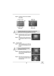
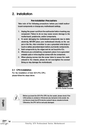
... CPU surface is found. Otherwise, the CPU will be seriously damaged. Step 1-2. Step 1-3. Open the socket: Step 1-1. Keep the right lever positioned at about 90 degrees in the socket. Insert the 2011-Pin CPU: Pin1 Step 2-1. Disengage the right lever by pressing it down and sliding it out of ...Intel 2011-Pin CPU, please follow the steps below. 2011-Pin Socket Overview Before you insert the 2011-Pin CPU into the socket if above situation is unclean or if there are any bent pins in order to &#...
... CPU surface is found. Otherwise, the CPU will be seriously damaged. Step 1-2. Step 1-3. Open the socket: Step 1-1. Keep the right lever positioned at about 90 degrees in the socket. Insert the 2011-Pin CPU: Pin1 Step 2-1. Disengage the right lever by pressing it down and sliding it out of ...Intel 2011-Pin CPU, please follow the steps below. 2011-Pin Socket Overview Before you insert the 2011-Pin CPU into the socket if above situation is unclean or if there are any bent pins in order to &#...
User Manual
Page 19
... cover must be placed if returning the motherboard for after service. orientation key notch Pin1 alignment key orientation key notch 2011-Pin CPU alignment key 2011-Pin Socket For proper inserting, please ensure to the orient keys. Step 3-2. Step 2-2. Flip the load plate onto the IHS, then the cover... load lever, and secure it with the load plate tab under the retention tab. 19 Carefully place the CPU into the socket by itself. Step 2-4. Close the socket: Step 3-1. Step 3-3. Press down the right load lever, and secure it with the four alignment keys of the CPU ...
... cover must be placed if returning the motherboard for after service. orientation key notch Pin1 alignment key orientation key notch 2011-Pin CPU alignment key 2011-Pin Socket For proper inserting, please ensure to the orient keys. Step 3-2. Step 2-2. Flip the load plate onto the IHS, then the cover... load lever, and secure it with the load plate tab under the retention tab. 19 Carefully place the CPU into the socket by itself. Step 2-4. Close the socket: Step 3-1. Step 3-3. Press down the right load lever, and secure it with the four alignment keys of the CPU ...
User Manual
Page 20
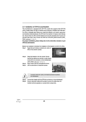
.... 5). Step 5. Step 2. Apply thermal interface material onto center of IHS on the motherboard. Please adopt the type of the heatsink for 2011-Pin CPUs. For proper installation, please kindly refer to illustrate the installation of heatsink and cooling fan compliant with tie-wrap to the CPU ...fan connector on the motherboard. Place the heatsink onto the socket. If you need to spray thermal interface material between the CPU and the heatsink to dissipate heat. Below is equipped with 2011-Pin socket that the CPU and the heatsink are oriented on side closest to...
.... 5). Step 5. Step 2. Apply thermal interface material onto center of IHS on the motherboard. Please adopt the type of the heatsink for 2011-Pin CPUs. For proper installation, please kindly refer to illustrate the installation of heatsink and cooling fan compliant with tie-wrap to the CPU ...fan connector on the motherboard. Place the heatsink onto the socket. If you need to spray thermal interface material between the CPU and the heatsink to dissipate heat. Below is equipped with 2011-Pin socket that the CPU and the heatsink are oriented on side closest to...
User Manual
Page 22
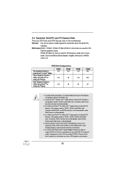
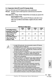
... PCIE4 x16 x16 x8 PCIE5 N/A N/A x8 1. PCI slot: PCI slot is recommended to install expansion cards that have the 32-bit PCI interface. Such as ASRock Game Blaster, Gigabit LAN card or SATA2 cards, etc. Therefore, both PCIE1 and PCIE4 will work at x16 bandwidth, while PCIE2 works at x8 bandwidth... PCIE1, PCIE2, PCIE4 and PCIE5 slots. Please connect a chassis fan to enable PCIE 3.0. It depends on future CPU updates and releases. 22 Currently Intel® Socket 2011 Sandy Bridge-E Processor doesn't support PCIE 3.0, but this motherboard.
... PCIE4 x16 x16 x8 PCIE5 N/A N/A x8 1. PCI slot: PCI slot is recommended to install expansion cards that have the 32-bit PCI interface. Such as ASRock Game Blaster, Gigabit LAN card or SATA2 cards, etc. Therefore, both PCIE1 and PCIE4 will work at x16 bandwidth, while PCIE2 works at x8 bandwidth... PCIE1, PCIE2, PCIE4 and PCIE5 slots. Please connect a chassis fan to enable PCIE 3.0. It depends on future CPU updates and releases. 22 Currently Intel® Socket 2011 Sandy Bridge-E Processor doesn't support PCIE 3.0, but this motherboard.

Quick Installation Guide
Page 4
... 26 25 24 23 22 21 20 1 2 x 240-pin DDR3 DIMM Slots 24 Dr. Debug (DDR3_A1, DDR3_B1, Black) 25 Clear CMOS Jumper (CLRCMOS1) 2 2011-Pin CPU Socket 26 Intel X79 Chipset 3 ATX 12V Power Connector (ATX12V1) 27 USB 2.0 Header (USB_10_11, Black) 4 2 x 240-pin DDR3 DIMM Slots 28 USB 2.0 Header (USB_8_9, Black) (DDR3_D1, DDR3_C1..., Black) 22 System Panel Header (PANEL1, Black) 43 PCI Express 3.0 x16 Slot (PCIE1, Red) 23 Power LED Header (PLED1) 44 Power Fan Connector (PWR_FAN1) English 4 Fatal1ty X79 Professional Series Motherboard
... 26 25 24 23 22 21 20 1 2 x 240-pin DDR3 DIMM Slots 24 Dr. Debug (DDR3_A1, DDR3_B1, Black) 25 Clear CMOS Jumper (CLRCMOS1) 2 2011-Pin CPU Socket 26 Intel X79 Chipset 3 ATX 12V Power Connector (ATX12V1) 27 USB 2.0 Header (USB_10_11, Black) 4 2 x 240-pin DDR3 DIMM Slots 28 USB 2.0 Header (USB_8_9, Black) (DDR3_D1, DDR3_C1..., Black) 22 System Panel Header (PANEL1, Black) 43 PCI Express 3.0 x16 Slot (PCIE1, Red) 23 Power LED Header (PLED1) 44 Power Fan Connector (PWR_FAN1) English 4 Fatal1ty X79 Professional Series Motherboard

Quick Installation Guide
Page 8
... x PS/2 Keyboard Port 8 Fatal1ty X79 Professional Series Motherboard English quality Conductive Polymer Capacitors) - Supports AMD Quad CrossFireXTM, 4-Way CrossFireXTM, 3-Way CrossFireXTM and CrossFireXTM - Supports Intel® CoreTM i7 processor family for the LGA 2011 Socket - Supports Intel® Turbo Boost...Gigabit LAN 10/100/1000 Mb/s - ATX Form Factor: 12.0-in x 9.6-in socket LGA 2011 - Advanced 16 + 2 Power Phase Design - Supports PXE I /O - Intel® X79 - Supports THX TruStudioTM - Supports Energy Efficient Ethernet 802.3az - Premium Gold Capacitor...
... x PS/2 Keyboard Port 8 Fatal1ty X79 Professional Series Motherboard English quality Conductive Polymer Capacitors) - Supports AMD Quad CrossFireXTM, 4-Way CrossFireXTM, 3-Way CrossFireXTM and CrossFireXTM - Supports Intel® CoreTM i7 processor family for the LGA 2011 Socket - Supports Intel® Turbo Boost...Gigabit LAN 10/100/1000 Mb/s - ATX Form Factor: 12.0-in x 9.6-in socket LGA 2011 - Advanced 16 + 2 Power Phase Design - Supports PXE I /O - Intel® X79 - Supports THX TruStudioTM - Supports Energy Efficient Ethernet 802.3az - Premium Gold Capacitor...
Quick Installation Guide
Page 11
...2-channel, 4-channel, 6-channel, and 8-channel modes. In OC DNA mode, you to adjust the mouse polling rate of the Fatal1ty Mouse port to read the installation guide of your own risk and expense. In IES (Intelligent Energy Saver) mode, the voltage ...Fatal1ty X79 Professional Series Motherboard English ASRock Instant Flash is a BIOS flash utility embedded in the BIOS, applying Untied Overclocking Technology, or using third-party overclocking tools. WARNING Please realize that Windows® cannot use ASRock XFast RAM to get the same OC settings. Currently Intel® Socket 2011...
...2-channel, 4-channel, 6-channel, and 8-channel modes. In OC DNA mode, you to adjust the mouse polling rate of the Fatal1ty Mouse port to read the installation guide of your own risk and expense. In IES (Intelligent Energy Saver) mode, the voltage ...Fatal1ty X79 Professional Series Motherboard English ASRock Instant Flash is a BIOS flash utility embedded in the BIOS, applying Untied Overclocking Technology, or using third-party overclocking tools. WARNING Please realize that Windows® cannot use ASRock XFast RAM to get the same OC settings. Currently Intel® Socket 2011...
Quick Installation Guide
Page 14
...to the chassis, please do not touch the ICs. 4. Otherwise, the CPU will be seriously damaged. 14 Fatal1ty X79 Professional Series Motherboard English When placing screws into the socket, please check if the CPU surface is found. Doing so may cause severe damage to do so may damage ...like. 2. Installation Pre-installation Precautions Take note of Intel 2011-Pin CPU, please follow the steps below. 2011-Pin Socket Overview Before you handle components. 3. Unplug the power cord from the wall socket before you insert the 2011-Pin CPU into the screw holes to insert the CPU ...
...to the chassis, please do not touch the ICs. 4. Otherwise, the CPU will be seriously damaged. 14 Fatal1ty X79 Professional Series Motherboard English When placing screws into the socket, please check if the CPU surface is found. Doing so may cause severe damage to do so may damage ...like. 2. Installation Pre-installation Precautions Take note of Intel 2011-Pin CPU, please follow the steps below. 2011-Pin Socket Overview Before you handle components. 3. Unplug the power cord from the wall socket before you insert the 2011-Pin CPU into the screw holes to insert the CPU ...

Quick Installation Guide
Page 15
... by pressing it down and sliding it out of the hook. Step 1-3. orientation key notch Pin1 alignment key English orientation key notch 2011-Pin CPU alignment key 2011-Pin Socket 15 Fatal1ty X79 Professional Series Motherboard Disengage the left lever by the edge with the triangle mark(Pin 1) on your upper right corner. Keep the right...
... by pressing it down and sliding it out of the hook. Step 1-3. orientation key notch Pin1 alignment key English orientation key notch 2011-Pin CPU alignment key 2011-Pin Socket 15 Fatal1ty X79 Professional Series Motherboard Disengage the left lever by the edge with the triangle mark(Pin 1) on your upper right corner. Keep the right...
Quick Installation Guide
Page 17
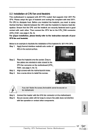
...compliant with 2011-Pin socket that the CPU and the heatsink are oriented on side closest to the CPU fan connector on the motherboard. For proper installation, please kindly refer to the instruction manuals of IHS on the motherboard. Step 2. English 17 Fatal1ty X79 Professional Series ...Motherboard 2.2 Installation of CPU Fan and Heatsink This motherboard is an example to illustrate the installation of the heatsink for 2011-Pin CPU. Align screws with each other components. Step 4. ...
...compliant with 2011-Pin socket that the CPU and the heatsink are oriented on side closest to the CPU fan connector on the motherboard. For proper installation, please kindly refer to the instruction manuals of IHS on the motherboard. Step 2. English 17 Fatal1ty X79 Professional Series ...Motherboard 2.2 Installation of CPU Fan and Heatsink This motherboard is an example to illustrate the installation of the heatsink for 2011-Pin CPU. Align screws with each other components. Step 4. ...
Quick Installation Guide
Page 19
Such as ASRock Game Blaster, Gigabit LAN card or SATA2 cards, ...(PCIE 3.0 x16 slots) are 2 PCI slots and 5 PCI Express slots on future CPU updates and releases. 19 Fatal1ty X79 Professional Series Motherboard English PCIE3 (PCIE2.0 x1 slot) is used for better thermal environment. 6. PCIE Slot Configurations PCIE1 PCIE2 PCIE4... PCIE1 will work at x16 bandwidth, while PCIE2, PCIE4 and PCIE5 works at x8 bandwidth. 5. Currently Intel® Socket 2011 Sandy Bridge-E Processor doesn't support PCIE 3.0, but this motherboard. It depends on Intel's CPU to the motherboard's chassis...
Such as ASRock Game Blaster, Gigabit LAN card or SATA2 cards, ...(PCIE 3.0 x16 slots) are 2 PCI slots and 5 PCI Express slots on future CPU updates and releases. 19 Fatal1ty X79 Professional Series Motherboard English PCIE3 (PCIE2.0 x1 slot) is used for better thermal environment. 6. PCIE Slot Configurations PCIE1 PCIE2 PCIE4... PCIE1 will work at x16 bandwidth, while PCIE2, PCIE4 and PCIE5 works at x8 bandwidth. 5. Currently Intel® Socket 2011 Sandy Bridge-E Processor doesn't support PCIE 3.0, but this motherboard. It depends on Intel's CPU to the motherboard's chassis...
