
User Manual
Page 8
...-LAN - Supports Energy Efficient Ethernet 802.3az - Supports Intel® CoreTM i7 processor family for the LGA 2011 Socket - Intel® X79 - PCIE x1 Gigabit LAN 10/100/1000 Mb/s - Supports Intel® Extreme Memory Profile (XMP)1.3/1.2 -... Specifications Platform CPU Chipset Memory Expansion Slot Audio LAN Rear Panel I /O Panel - 1 x PS/2 Keyboard Port 8 ATX Form Factor: 12.0-in x 9.6-in socket LGA 2011 - Premium Gold Capacitor design (100% Japan-made high- Digital PWM Design - Quad Channel DDR3 Memory Technology (see CAUTION 4) - 1 x PCI Express 2.0 x ...
...-LAN - Supports Energy Efficient Ethernet 802.3az - Supports Intel® CoreTM i7 processor family for the LGA 2011 Socket - Intel® X79 - PCIE x1 Gigabit LAN 10/100/1000 Mb/s - Supports Intel® Extreme Memory Profile (XMP)1.3/1.2 -... Specifications Platform CPU Chipset Memory Expansion Slot Audio LAN Rear Panel I /O Panel - 1 x PS/2 Keyboard Port 8 ATX Form Factor: 12.0-in x 9.6-in socket LGA 2011 - Premium Gold Capacitor design (100% Japan-made high- Digital PWM Design - Quad Channel DDR3 Memory Technology (see CAUTION 4) - 1 x PCI Express 2.0 x ...
User Manual
Page 14
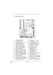
... CTR BASS 8 PWR_FAN1 USB3_5_6 1 USB3_7_8 1 Top: LINE IN Center: FRONT Bottom: MIC IN 9 44 43 PCIE1 X79 Professional 64Mb BIOS 10 42 PCI1 11 SATA2_2_3 CHA_FAN1 FATAL1TY SATA3 6Gb/s 12 41 PCIE2 LAN SATA2_0_1 PHY 2 oz Copper PCB 1394a 13 CMOS 40 PCIE3 Battery SATA3_0_1 Super I/O ...24 23 22 21 20 1 2 x 240-pin DDR3 DIMM Slots 24 Dr. Debug (DDR3_A1, DDR3_B1, Black) 25 Clear CMOS Jumper (CLRCMOS1) 2 2011-Pin CPU Socket 26 Intel X79 Chipset 3 ATX 12V Power Connector (ATX12V1) 27 USB 2.0 Header (USB_10_11, Black) 4 2 x 240-pin DDR3 DIMM Slots 28 USB 2.0 Header (...
... CTR BASS 8 PWR_FAN1 USB3_5_6 1 USB3_7_8 1 Top: LINE IN Center: FRONT Bottom: MIC IN 9 44 43 PCIE1 X79 Professional 64Mb BIOS 10 42 PCI1 11 SATA2_2_3 CHA_FAN1 FATAL1TY SATA3 6Gb/s 12 41 PCIE2 LAN SATA2_0_1 PHY 2 oz Copper PCB 1394a 13 CMOS 40 PCIE3 Battery SATA3_0_1 Super I/O ...24 23 22 21 20 1 2 x 240-pin DDR3 DIMM Slots 24 Dr. Debug (DDR3_A1, DDR3_B1, Black) 25 Clear CMOS Jumper (CLRCMOS1) 2 2011-Pin CPU Socket 26 Intel X79 Chipset 3 ATX 12V Power Connector (ATX12V1) 27 USB 2.0 Header (USB_10_11, Black) 4 2 x 240-pin DDR3 DIMM Slots 28 USB 2.0 Header (...

Quick Installation Guide
Page 4
... CTR BASS 8 PWR_FAN1 USB3_5_6 1 USB3_7_8 1 Top: LINE IN Center: FRONT Bottom: MIC IN 9 44 43 PCIE1 X79 Professional 64Mb BIOS 10 42 PCI1 11 SATA2_2_3 CHA_FAN1 FATAL1TY SATA3 6Gb/s 12 41 PCIE2 LAN SATA2_0_1 PHY 2 oz Copper PCB 1394a 13 CMOS 40 PCIE3 Battery SATA3_0_1 Super I/O ...24 23 22 21 20 1 2 x 240-pin DDR3 DIMM Slots 24 Dr. Debug (DDR3_A1, DDR3_B1, Black) 25 Clear CMOS Jumper (CLRCMOS1) 2 2011-Pin CPU Socket 26 Intel X79 Chipset 3 ATX 12V Power Connector (ATX12V1) 27 USB 2.0 Header (USB_10_11, Black) 4 2 x 240-pin DDR3 DIMM Slots 28 USB 2.0 Header (...
... CTR BASS 8 PWR_FAN1 USB3_5_6 1 USB3_7_8 1 Top: LINE IN Center: FRONT Bottom: MIC IN 9 44 43 PCIE1 X79 Professional 64Mb BIOS 10 42 PCI1 11 SATA2_2_3 CHA_FAN1 FATAL1TY SATA3 6Gb/s 12 41 PCIE2 LAN SATA2_0_1 PHY 2 oz Copper PCB 1394a 13 CMOS 40 PCIE3 Battery SATA3_0_1 Super I/O ...24 23 22 21 20 1 2 x 240-pin DDR3 DIMM Slots 24 Dr. Debug (DDR3_A1, DDR3_B1, Black) 25 Clear CMOS Jumper (CLRCMOS1) 2 2011-Pin CPU Socket 26 Intel X79 Chipset 3 ATX 12V Power Connector (ATX12V1) 27 USB 2.0 Header (USB_10_11, Black) 4 2 x 240-pin DDR3 DIMM Slots 28 USB 2.0 Header (...

Quick Installation Guide
Page 8
ATX Form Factor: 12.0-in x 9.6-in socket LGA 2011 - Supports Intel® CoreTM i7 processor family for the LGA 2011 Socket - Digital PWM Design - Supports Intel® Extreme Memory Profile (XMP)1.3/1.2 - 4 x PCI Express 3.0 x16 slots (PCIE1/PCIE2/PCIE4/PCIE5: ....5 cm x 24.4 cm - 1.2 Specifications Platform CPU Chipset Memory Expansion Slot Audio LAN Rear Panel I /O Panel - 1 x PS/2 Keyboard Port 8 Fatal1ty X79 Professional Series Motherboard English Supports DDR3 2400+(OC)/2133(OC)/1866(OC)/1600/1333/ 1066 non-ECC, un-buffered memory - capacity of system memory: 32GB (see...
ATX Form Factor: 12.0-in x 9.6-in socket LGA 2011 - Supports Intel® CoreTM i7 processor family for the LGA 2011 Socket - Digital PWM Design - Supports Intel® Extreme Memory Profile (XMP)1.3/1.2 - 4 x PCI Express 3.0 x16 slots (PCIE1/PCIE2/PCIE4/PCIE5: ....5 cm x 24.4 cm - 1.2 Specifications Platform CPU Chipset Memory Expansion Slot Audio LAN Rear Panel I /O Panel - 1 x PS/2 Keyboard Port 8 Fatal1ty X79 Professional Series Motherboard English Supports DDR3 2400+(OC)/2133(OC)/1866(OC)/1600/1333/ 1066 non-ECC, un-buffered memory - capacity of system memory: 32GB (see...
Quick Installation Guide
Page 11
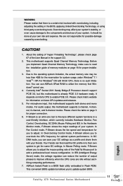
... Currently Intel® Socket 2011 Sandy Bridge-E Processor doesn't support PCIE 3.0, but this motherboard is an all-in the BIOS, applying Untied Overclocking Technology, or using third-party overclocking tools. Please check the table on Intel's CPU to update system BIOS 11 Fatal1ty X79 Professional Series Motherboard English F-Stream.... In IES (Intelligent Energy Saver) mode, the voltage regulator can then load the OC profile in Flash ROM. ASRock Instant Flash is a BIOS flash utility embedded in to their own system to overclock the CPU frequency for proper connection. 6.
... Currently Intel® Socket 2011 Sandy Bridge-E Processor doesn't support PCIE 3.0, but this motherboard is an all-in the BIOS, applying Untied Overclocking Technology, or using third-party overclocking tools. Please check the table on Intel's CPU to update system BIOS 11 Fatal1ty X79 Professional Series Motherboard English F-Stream.... In IES (Intelligent Energy Saver) mode, the voltage regulator can then load the OC profile in Flash ROM. ASRock Instant Flash is a BIOS flash utility embedded in to their own system to overclock the CPU frequency for proper connection. 6.
Quick Installation Guide
Page 14
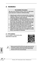
.... Do not force to the motherboard, peripherals, and/or components. 2. Otherwise, the CPU will be seriously damaged. 14 Fatal1ty X79 Professional Series Motherboard English Unplug the power cord from the wall socket before you insert the 2011-Pin CPU into the screw holes to do so may damage the motherboard. 2.1 CPU Installation For the installation...
.... Do not force to the motherboard, peripherals, and/or components. 2. Otherwise, the CPU will be seriously damaged. 14 Fatal1ty X79 Professional Series Motherboard English Unplug the power cord from the wall socket before you insert the 2011-Pin CPU into the screw holes to do so may damage the motherboard. 2.1 CPU Installation For the installation...

Quick Installation Guide
Page 15
Step 1. Insert the 2011-Pin CPU: Pin1 Step 2-1. Step 1-2. Disengage the right lever by pressing it down and sliding it out of the hook. Step 1-3. Keep the right lever ... the hook. Step 2-2. Locate Pin1 and the two orientation key notches. orientation key notch Pin1 alignment key English orientation key notch 2011-Pin CPU alignment key 2011-Pin Socket 15 Fatal1ty X79 Professional Series Motherboard Open the socket: Step 1-1. Step 2. Disengage the left lever by the edge with the triangle mark(Pin 1) on your upper right corner.
Step 1. Insert the 2011-Pin CPU: Pin1 Step 2-1. Step 1-2. Disengage the right lever by pressing it down and sliding it out of the hook. Step 1-3. Keep the right lever ... the hook. Step 2-2. Locate Pin1 and the two orientation key notches. orientation key notch Pin1 alignment key English orientation key notch 2011-Pin CPU alignment key 2011-Pin Socket 15 Fatal1ty X79 Professional Series Motherboard Open the socket: Step 1-1. Step 2. Disengage the left lever by the edge with the triangle mark(Pin 1) on your upper right corner.
Quick Installation Guide
Page 17
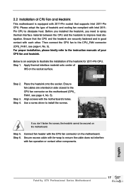
...cooling fan compliant with the motherboard's holes. Ensure that supports Intel 2011-Pin CPU. Secure excess cable with tie-wrap to the instruction manuals of your CPU fan and heatsink. English 17 Fatal1ty X79 Professional Series Motherboard 2.2 Installation of CPU Fan and Heatsink This motherboard is...fasten the screws, the heatsink cannot be secured on the socket surface. Place the heatsink onto the socket. Step 6. For proper installation, please kindly refer to ensure the cable does not interfere with 2011-Pin socket that the CPU and the heatsink are oriented on side ...
...cooling fan compliant with the motherboard's holes. Ensure that supports Intel 2011-Pin CPU. Secure excess cable with tie-wrap to the instruction manuals of your CPU fan and heatsink. English 17 Fatal1ty X79 Professional Series Motherboard 2.2 Installation of CPU Fan and Heatsink This motherboard is...fasten the screws, the heatsink cannot be secured on the socket surface. Place the heatsink onto the socket. Step 6. For proper installation, please kindly refer to ensure the cable does not interfere with 2011-Pin socket that the CPU and the heatsink are oriented on side ...
Quick Installation Guide
Page 19
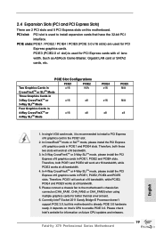
Such as ASRock Game Blaster, Gigabit LAN card or SATA2 cards, etc. In CrossFireXTM mode or SLITM mode, please install the PCI Express x16 graphics cards in PCIE1, ... a chassis fan to install a PCI Express x16 graphics card in the PCIE1 slot. 2. Currently Intel® Socket 2011 Sandy Bridge-E Processor doesn't support PCIE 3.0, but this motherboard. It depends on future CPU updates and releases. 19 Fatal1ty X79 Professional Series Motherboard English PCIE Slot Configurations PCIE1 PCIE2 PCIE4 PCIE5 Two Graphics Cards in CrossFireXTM or...
Such as ASRock Game Blaster, Gigabit LAN card or SATA2 cards, etc. In CrossFireXTM mode or SLITM mode, please install the PCI Express x16 graphics cards in PCIE1, ... a chassis fan to install a PCI Express x16 graphics card in the PCIE1 slot. 2. Currently Intel® Socket 2011 Sandy Bridge-E Processor doesn't support PCIE 3.0, but this motherboard. It depends on future CPU updates and releases. 19 Fatal1ty X79 Professional Series Motherboard English PCIE Slot Configurations PCIE1 PCIE2 PCIE4 PCIE5 Two Graphics Cards in CrossFireXTM or...


