User Manual
Page 3
...PCI and PCI Express slots 17 2.5 SLITM Operation Guide 18 2.6 Jumpers Setup 22 2.7 Onboard Headers and Connectors 23 2.8 HDMI_SPDIF Header Connection Guide 28 2.9 eSATAII Interface Introduction 29 2.10 SATAII Hard Disk Setup Guide 32 2.11 Serial ATA (SATA) / Serial ATAII ...(SATAII) Hard Disks Installation 33 2.12 Hot Plug and Hot Swap Functions for SLITM Mode 10 1.5 Motherboard Layout 11 1.6 ASRock 1394_eSATAII I/O Plus 12 2 . Introduction 5 1.1 Package Contents 5 1.2 Specifications 6 1.3 Minimum Hardware Requirement Table for Windows® VistaTM Premium 2007...
...PCI and PCI Express slots 17 2.5 SLITM Operation Guide 18 2.6 Jumpers Setup 22 2.7 Onboard Headers and Connectors 23 2.8 HDMI_SPDIF Header Connection Guide 28 2.9 eSATAII Interface Introduction 29 2.10 SATAII Hard Disk Setup Guide 32 2.11 Serial ATA (SATA) / Serial ATAII ...(SATAII) Hard Disks Installation 33 2.12 Hot Plug and Hot Swap Functions for SLITM Mode 10 1.5 Motherboard Layout 11 1.6 ASRock 1394_eSATAII I/O Plus 12 2 . Introduction 5 1.1 Package Contents 5 1.2 Specifications 6 1.3 Minimum Hardware Requirement Table for Windows® VistaTM Premium 2007...
User Manual
Page 8
...for system usage under Windows® XP and Windows® VistaTM. This motherboard supports Untied Overclocking Technology. This motherboard supports ASRock AM2 Boost overclocking technology. If you enable this motherboard offers stepless control, it is a certain risk involved with 64-bit...PCI Express VGA Card List for SLITM Mode" on page 15 for SLITM function. Frequencies other than 4GB for the reservation for proper connection. 8 For microphone input, this motherboard supports 2-channel, 4-channel, 6-channel, and 8-channel modes. We are intended for proper installation....
...for system usage under Windows® XP and Windows® VistaTM. This motherboard supports Untied Overclocking Technology. This motherboard supports ASRock AM2 Boost overclocking technology. If you enable this motherboard offers stepless control, it is a certain risk involved with 64-bit...PCI Express VGA Card List for SLITM Mode" on page 15 for SLITM function. Frequencies other than 4GB for the reservation for proper connection. 8 For microphone input, this motherboard supports 2-channel, 4-channel, 6-channel, and 8-channel modes. We are intended for proper installation....
User Manual
Page 9
You can also connect SATA hard disk to submit Windows® VistaTM Premium 2007 and Basic logo, please follow below table for details about eSATAII and eSATAII installation procedures. ... with 128bit VGA memory (Premium) with 64bit VGA memory (Basic) * After June 1, 2007, all Windows® VistaTM systems are required to SATAII mode. ASRock website http://www.asrock.com 1.3 Minimum Hardware Requirement Table for audio function test. 9 Please visit our website for USB 2.0 works fine under Microsoft® Windows® VistaTM 64...
You can also connect SATA hard disk to submit Windows® VistaTM Premium 2007 and Basic logo, please follow below table for details about eSATAII and eSATAII installation procedures. ... with 128bit VGA memory (Premium) with 64bit VGA memory (Basic) * After June 1, 2007, all Windows® VistaTM systems are required to SATAII mode. ASRock website http://www.asrock.com 1.3 Minimum Hardware Requirement Table for audio function test. 9 Please visit our website for USB 2.0 works fine under Microsoft® Windows® VistaTM 64...

User Manual
Page 12
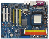
..., 6-channel or 8-channel), then the copy source function of speaker you use 2-channel speaker, please connect the speaker's plug into "Front Speaker Jack". 1.6 ASRock 1394_eSATAII I/O Plus 1 PS/2 Mouse Port (Green) 2 Parallel Port 3 IEEE 1394 Port 4 RJ-45 Port 5 Side Speaker (Gray) 6 Rear Speaker (Black) 7 Central / ... the type of C-Media audio application can work properly. * If you use . See the table below for Audio Output Connection Audio Output Channels Front Speaker Rear Speaker (No. 9) (No. 6) Central / Bass Side Speaker (No. 7) (No. 5) 2 V -- -- -- 4 V -- -- ...
..., 6-channel or 8-channel), then the copy source function of speaker you use 2-channel speaker, please connect the speaker's plug into "Front Speaker Jack". 1.6 ASRock 1394_eSATAII I/O Plus 1 PS/2 Mouse Port (Green) 2 Parallel Port 3 IEEE 1394 Port 4 RJ-45 Port 5 Side Speaker (Gray) 6 Rear Speaker (Black) 7 Central / ... the type of C-Media audio application can work properly. * If you use . See the table below for Audio Output Connection Audio Output Channels Front Speaker Rear Speaker (No. 9) (No. 6) Central / Bass Side Speaker (No. 7) (No. 5) 2 V -- -- -- 4 V -- -- ...

User Manual
Page 14
... 2 / STEP 3: Match The CPU Golden Triangle To The Socket Corner Small Triangle STEP 4: Push Down And Lock The Socket Lever 2.2 Installation of the pins. Then connect the CPU fan to avoid bending of CPU Fan and Heatsink After you push down the socket lever to the instruction manuals of the CPU...
... 2 / STEP 3: Match The CPU Golden Triangle To The Socket Corner Small Triangle STEP 4: Push Down And Lock The Socket Lever 2.2 Installation of the pins. Then connect the CPU fan to avoid bending of CPU Fan and Heatsink After you push down the socket lever to the instruction manuals of the CPU...
User Manual
Page 18
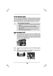
... version shall be the same.) Insert one graphics card into PCIE2 slot and another graphics card to the PCI Express graphics cards. Step2. If required, connect an auxiliary power source to PCIE4 slot. Install the identical SLITM-ready graphics cards that your power supply unit (PSU) can provide at least the...
... version shall be the same.) Insert one graphics card into PCIE2 slot and another graphics card to the PCI Express graphics cards. Step2. If required, connect an auxiliary power source to PCIE4 slot. Install the identical SLITM-ready graphics cards that your power supply unit (PSU) can provide at least the...

User Manual
Page 19
...-I cable to PCIE2 slot. Install the graphics card drivers to SLI/XFIRE power connector. From the nView Desktop Manager window, select the Desktop Management tab. Connect a 4-pin ATX power cable to your Windows® taskbar. After that is inserted to the monitor connector and the DVI connector of the graphics card...
...-I cable to PCIE2 slot. Install the graphics card drivers to SLI/XFIRE power connector. From the nView Desktop Manager window, select the Desktop Management tab. Connect a 4-pin ATX power cable to your Windows® taskbar. After that is inserted to the monitor connector and the DVI connector of the graphics card...
User Manual
Page 23
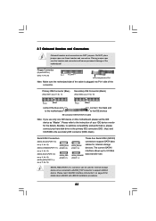
...(SATAII_BLUE (PORT 2.0): see p.11, No. 15) (SATAII_RED (PORT 2.1): see p.11 No. 10) PIN1 IDE1 PIN1 IDE2 connect the blue end to the motherboard connect the black end to 3.0 Gb/s data transfer rate. Please refer to the secondary IDE connector (IDE2, black). Besides, to ...support eSATAII device. SATAII_RED (PORT 2.1) connector can be connected to eSATAII_TOP connector to optimize compatibility and performance, please connect your IDE device vendor for details about eSATAII and eSATAII installation procedures. 23 Please read "...
...(SATAII_BLUE (PORT 2.0): see p.11, No. 15) (SATAII_RED (PORT 2.1): see p.11 No. 10) PIN1 IDE1 PIN1 IDE2 connect the blue end to the motherboard connect the black end to 3.0 Gb/s data transfer rate. Please refer to the secondary IDE connector (IDE2, black). Besides, to ...support eSATAII device. SATAII_RED (PORT 2.1) connector can be connected to eSATAII_TOP connector to optimize compatibility and performance, please connect your IDE device vendor for details about eSATAII and eSATAII installation procedures. 23 Please read "...

User Manual
Page 24
...the I/O panel, there are two USB 2.0 headers on this motherboard. Serial ATA (SATA) Power Cable (Optional) connect to the SATA HDD power connector connect to the power supply Please connect the black end of SATA power cable to 3.0 Gb/s data transfer rate. Serial ATA (SATA) Data Cable ...or the SATAII connector on each drive. The current eSATAII interface allows up to the power connector of the SATA data cable can be connected to connect SATAII_RED (PORT 2.1) connector and eSATAII connector. You can support two USB 2.0 ports. Infrared Module Header (5-pin IR1) (see p.11,...
...the I/O panel, there are two USB 2.0 headers on this motherboard. Serial ATA (SATA) Power Cable (Optional) connect to the SATA HDD power connector connect to the power supply Please connect the black end of SATA power cable to 3.0 Gb/s data transfer rate. Serial ATA (SATA) Data Cable ...or the SATAII connector on each drive. The current eSATAII interface allows up to the power connector of the SATA data cable can be connected to connect SATAII_RED (PORT 2.1) connector and eSATAII connector. You can support two USB 2.0 ports. Infrared Module Header (5-pin IR1) (see p.11,...

User Manual
Page 25
...control of audio devices. If you to the ground pin. CPU Fan Connector (4-pin CPU_FAN1) (see p.11, No. 36) Please connect the CPU fan 1 GND cable to this connector and match the black wire to receive stereo audio input from sound sources such as a... (4-pin SPEAKER 1) (see p.11, No. 21) Chassis Fan Connector (3-pin CHA_FAN1) (see p.11 No. 27) GND BACKOUT-R BACKOUT-L 1 A U D - Though this header. Please connect a chassis fan cable to this connector and 2 +12V 3 CPU_FAN_SPEED match the black wire to Pin 1-3. Front Panel Audio Header (8-pin AUDIO1) (see p.11, No. 20...
...control of audio devices. If you to the ground pin. CPU Fan Connector (4-pin CPU_FAN1) (see p.11, No. 36) Please connect the CPU fan 1 GND cable to this connector and match the black wire to receive stereo audio input from sound sources such as a... (4-pin SPEAKER 1) (see p.11, No. 21) Chassis Fan Connector (3-pin CHA_FAN1) (see p.11 No. 27) GND BACKOUT-R BACKOUT-L 1 A U D - Though this header. Please connect a chassis fan cable to this connector and 2 +12V 3 CPU_FAN_SPEED match the black wire to Pin 1-3. Front Panel Audio Header (8-pin AUDIO1) (see p.11, No. 20...

User Manual
Page 26
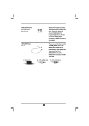
...FRONT_1394) (see p.11 No. 3) SLI/XFIRE_POWER1 It is one IEEE 1394 port. 26 Besides one default IEEE 1394 port on this motherboard at the same time. Failing to this header if the Game port bracket is necessary to connect a power supply with a hard disk power connecor when two graphics cards...JAB2 JAY GND GND JAX JAB1 +5V RXTPAM_0 GND RXTPBM_0 +12V GND 1 +12V RXTPBP_0 GND RXTPAP_0 Connect a Game cable to do so will cause power up failure. This IEEE 1394 header can support one IEEE 1394 header (FRONT_1394) on the I/O panel, there is not necessary to use this connector, but please...
...FRONT_1394) (see p.11 No. 3) SLI/XFIRE_POWER1 It is one IEEE 1394 port. 26 Besides one default IEEE 1394 port on this motherboard at the same time. Failing to this header if the Game port bracket is necessary to connect a power supply with a hard disk power connecor when two graphics cards...JAB2 JAY GND GND JAX JAB1 +5V RXTPAM_0 GND RXTPBM_0 +12V GND 1 +12V RXTPBP_0 GND RXTPAP_0 Connect a Game cable to do so will cause power up failure. This IEEE 1394 header can support one IEEE 1394 header (FRONT_1394) on the I/O panel, there is not necessary to use this connector, but please...
User Manual
Page 27
... end +5V SPDIFOUT GND blue black B. white end (2-pin) SPDIFOUT GND blue black C. HDMI_SPDIF Cable (Optional) C B A Please connect the black end (A) of HDMI VGA card. Please connect the HDMI_SPDIF connector of HDMI VGA card to connect HDMI Digital TV/ projector/LCD devices. HDMI_SPDIF Header (3-pin HDMI_SPDIF1) (see p.11, No. 31) 1 GND SPDIFOUT +5V...
... end +5V SPDIFOUT GND blue black B. white end (2-pin) SPDIFOUT GND blue black C. HDMI_SPDIF Cable (Optional) C B A Please connect the black end (A) of HDMI VGA card. Please connect the HDMI_SPDIF connector of HDMI VGA card to connect HDMI Digital TV/ projector/LCD devices. HDMI_SPDIF Header (3-pin HDMI_SPDIF1) (see p.11, No. 31) 1 GND SPDIFOUT +5V...

User Manual
Page 28
... audio/video source, such as a set-top box, DVD player, A/V receiver and a compatible digital audio or video monitor, such as HDTV. Incorrect connection may be damaged. Step 4. Install HDMI VGA card driver to this motherboard. Install the HDMI VGA card to the same pin definition. Make sure to... page 11, No. 31) on HDMI VGA card, please refer to page 27. Please refer to the VGA card user manual for detailed connection procedures. Step 5. Connect the black end (A) of HDMI_SPDIF cable to the HDMI_SPDIF connector of HDMI VGA card. (There are two white ends (2-pin and 3-pin) on...
... audio/video source, such as a set-top box, DVD player, A/V receiver and a compatible digital audio or video monitor, such as HDTV. Incorrect connection may be damaged. Step 4. Install HDMI VGA card driver to this motherboard. Install the HDMI VGA card to the same pin definition. Make sure to... page 11, No. 31) on HDMI VGA card, please refer to page 27. Please refer to the VGA card user manual for detailed connection procedures. Step 5. Connect the black end (A) of HDMI_SPDIF cable to the HDMI_SPDIF connector of HDMI VGA card. (There are two white ends (2-pin and 3-pin) on...

User Manual
Page 30
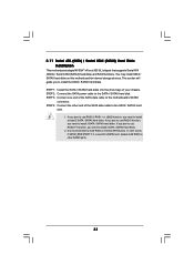
... data cable to the red SATAII connector (SATAII_RED (PORT 2.1)) Connect the SATA data cable to connect eSATAII device and the eSATAII port of the I/O shield. Connect one end of the eSATAII device cable to eSATAII device Connect the other end of the eSATAII device cable to eSATAII port of the I/O shield, you... need to connect the red SATAII connector (SATAII_RED (PORT 2.1); SATAII connector SATAII_RED (PORT 2.1) eSATAII connector (eSATAII_TOP) 1. In order to install eSATAII? see p.11 No.37) with a SATA...
... data cable to the red SATAII connector (SATAII_RED (PORT 2.1)) Connect the SATA data cable to connect eSATAII device and the eSATAII port of the I/O shield. Connect one end of the eSATAII device cable to eSATAII device Connect the other end of the eSATAII device cable to eSATAII port of the I/O shield, you... need to connect the red SATAII connector (SATAII_RED (PORT 2.1); SATAII connector SATAII_RED (PORT 2.1) eSATAII connector (eSATAII_TOP) 1. In order to install eSATAII? see p.11 No.37) with a SATA...
User Manual
Page 33
...is used for eSATAII port, please build RAID on this motherboard for internal storage devices. STEP 4: Connect the other end of the SATA data cable to build RAID on internal SATAII ports. STEP 3: Connect one end of your chassis. If you plan to use RAID 0, RAID 1 or JBOD function, ... you to install 3 SATA / SATAII hard disks. In other SATAII ports. 33 This section will guide you need to the motherboard's SATAII connector. STEP 2: Connect the SATA power cable to install 4 SATA / SATAII hard disks. 2. If you plan to use RAID 5 function, you need to the SATA / SATAII hard...
...is used for eSATAII port, please build RAID on this motherboard for internal storage devices. STEP 4: Connect the other end of the SATA data cable to build RAID on internal SATAII ports. STEP 3: Connect one end of your chassis. If you plan to use RAID 0, RAID 1 or JBOD function, ... you to install 3 SATA / SATAII hard disks. In other SATAII ports. 33 This section will guide you need to the motherboard's SATAII connector. STEP 2: Connect the SATA power cable to install 4 SATA / SATAII hard disks. 2. If you plan to use RAID 5 function, you need to the SATA / SATAII hard...
User Manual
Page 35
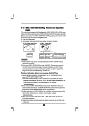
...is indicated in RAID mode. SATA power cable SATA 7-pin connector The SATA 15-pin power connector (Black) connect to SATA / SATAII HDD 1x4-pin conventional power connector (White) connect to support Hot Plug and will be processed. 2. Please follow below cable accessories from our motherboard package. ... IDE 1x4-pin conventional power connector interface is designed only for SATA / SATAII HDD in the product spec on our support website: www.asrock.com 4. Points of SATA / SATAII HDD Hot Plug feature carefully. 2.13 SATA / SATAII HDD Hot Plug Feature and Operation Guide This...
...is indicated in RAID mode. SATA power cable SATA 7-pin connector The SATA 15-pin power connector (Black) connect to SATA / SATAII HDD 1x4-pin conventional power connector (White) connect to support Hot Plug and will be processed. 2. Please follow below cable accessories from our motherboard package. ... IDE 1x4-pin conventional power connector interface is designed only for SATA / SATAII HDD in the product spec on our support website: www.asrock.com 4. Points of SATA / SATAII HDD Hot Plug feature carefully. 2.13 SATA / SATAII HDD Hot Plug Feature and Operation Guide This...
User Manual
Page 36
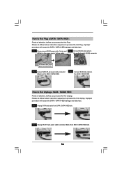
... cable from SATA / SATAII HDD side. 36 SATA power cable 1x4-pin power connector (White) Step 3 Connect SATA 15-pin power cable connector (Black) end to the SATA / SATAII HDD. Step 4 Connect SATA data cable to SATA / SATAII HDD. the motherboard's SATAII connector. How to Hot Plug a SATA ...you process the Hot Unplug: Please do follow below instruction sequence to the power supply 1x4-pin cable. Step 1 Please connect SATA power cable 1x4-pin end Step 2 Connect SATA data cable to (White) to process the Hot Plug, improper procedure will cause the SATA / SATAII HDD damage and...
... cable from SATA / SATAII HDD side. 36 SATA power cable 1x4-pin power connector (White) Step 3 Connect SATA 15-pin power cable connector (Black) end to the SATA / SATAII HDD. Step 4 Connect SATA data cable to SATA / SATAII HDD. the motherboard's SATAII connector. How to Hot Plug a SATA ...you process the Hot Unplug: Please do follow below instruction sequence to the power supply 1x4-pin cable. Step 1 Please connect SATA power cable 1x4-pin end Step 2 Connect SATA data cable to (White) to process the Hot Plug, improper procedure will cause the SATA / SATAII HDD damage and...

User Manual
Page 49
... [Auto]. This is enabled, it will enhance hard disk performance by optimizing the hard disk timing. Block (Multi-Sector Transfer) The default value of device connected to disable the LBA/Large mode. DMA Mode DMA capability allows the improved transfer-speed and data-integrity for Netware and UNIX user, select [Disabled...
... [Auto]. This is enabled, it will enhance hard disk performance by optimizing the hard disk timing. Block (Multi-Sector Transfer) The default value of device connected to disable the LBA/Large mode. DMA Mode DMA capability allows the improved transfer-speed and data-integrity for Netware and UNIX user, select [Disabled...
User Manual
Page 51
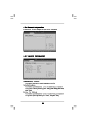
... or disable it . Configuration options: [Disabled], [2F8 / IRQ3], and [2E8 / IRQ3]. 51 3.3.6 Floppy Configuration In this section, you may configure the type of floppy drive connected to the system. +F1 F9 F10 ESC Select Screen Select Item Change Option General Help Load Defaults Save and Exit Exit v02.54 (C) Copyright 1985...
... or disable it . Configuration options: [Disabled], [2F8 / IRQ3], and [2E8 / IRQ3]. 51 3.3.6 Floppy Configuration In this section, you may configure the type of floppy drive connected to the system. +F1 F9 F10 ESC Select Screen Select Item Change Option General Help Load Defaults Save and Exit Exit v02.54 (C) Copyright 1985...

User Manual
Page 53
... or disable the support to identify the temperature of legacy OS (DOS) such as mouse, keyboard, USB flash... The default value is no USB device connected, "Auto" option will start to enable this section, it allows you install 4-pin CPU fan. 53 F1 F9 F10 ESC Select Screen Select Item General...
... or disable the support to identify the temperature of legacy OS (DOS) such as mouse, keyboard, USB flash... The default value is no USB device connected, "Auto" option will start to enable this section, it allows you install 4-pin CPU fan. 53 F1 F9 F10 ESC Select Screen Select Item General...

