
User Manual
Page 2
... not be reproduced, transcribed, transmitted, or translated in any language, in Perchlorate Best Management Practices (BMP) regulations passed by ASRock. In no responsibility for any kind, either expressed or implied, including but not limited to the implied warranties or conditions of...Material-special handling may be constructed as a commitment by the California Legislature. CALIFORNIA, USA ONLY The Lithium battery adopted on this motherboard contains Perchlorate, a toxic substance controlled in any form or by any means, except duplication of documentation by the purchaser for loss...
... not be reproduced, transcribed, transmitted, or translated in any language, in Perchlorate Best Management Practices (BMP) regulations passed by ASRock. In no responsibility for any kind, either expressed or implied, including but not limited to the implied warranties or conditions of...Material-special handling may be constructed as a commitment by the California Legislature. CALIFORNIA, USA ONLY The Lithium battery adopted on this motherboard contains Perchlorate, a toxic substance controlled in any form or by any means, except duplication of documentation by the purchaser for loss...
User Manual
Page 3
... Guide 32 2.11 Serial ATA (SATA) / Serial ATAII (SATAII) Hard Disks Installation 33 2.12 Hot Plug and Hot Swap Functions for SLITM Mode 10 1.5 Motherboard Layout 11 1.6 ASRock 1394_eSATAII I/O Plus 12 2 . Contents 1 . Introduction 5 1.1 Package Contents 5 1.2 Specifications 6 1.3 Minimum Hardware Requirement Table for Windows® VistaTM Premium 2007 and Basic Logo 9 1.4 Supported PCI Express...
... Guide 32 2.11 Serial ATA (SATA) / Serial ATAII (SATAII) Hard Disks Installation 33 2.12 Hot Plug and Hot Swap Functions for SLITM Mode 10 1.5 Motherboard Layout 11 1.6 ASRock 1394_eSATAII I/O Plus 12 2 . Contents 1 . Introduction 5 1.1 Package Contents 5 1.2 Specifications 6 1.3 Minimum Hardware Requirement Table for Windows® VistaTM Premium 2007 and Basic Logo 9 1.4 Supported PCI Express...

User Manual
Page 5
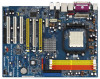
...may find the latest VGA cards and CPU support lists on ASRock website without notice. Introduction Thank you for purchasing ASRock ALiveNF5SLI-1394 motherboard, a reliable motherboard produced under ASRock's consistently stringent quality control. Chapter 3 and 4 contain the...motherboard and step-bystep guide to quality and endurance. ASRock website http://www.asrock.com 1.1 Package Contents 1 x ASRock ALiveNF5SLI-1394 Motherboard (ATX Form Factor: 12.0-in x 9.0-in, 30.5 cm x 22.9 cm) 1 x ASRock SLI Bridge 1 x ASRock ALiveNF5SLI-1394 Quick Installation Guide 1 x ASRock ALiveNF5SLI-1394 ...
...may find the latest VGA cards and CPU support lists on ASRock website without notice. Introduction Thank you for purchasing ASRock ALiveNF5SLI-1394 motherboard, a reliable motherboard produced under ASRock's consistently stringent quality control. Chapter 3 and 4 contain the...motherboard and step-bystep guide to quality and endurance. ASRock website http://www.asrock.com 1.1 Package Contents 1 x ASRock ALiveNF5SLI-1394 Motherboard (ATX Form Factor: 12.0-in x 9.0-in, 30.5 cm x 22.9 cm) 1 x ASRock SLI Bridge 1 x ASRock ALiveNF5SLI-1394 Quick Installation Guide 1 x ASRock ALiveNF5SLI-1394 ...
User Manual
Page 8
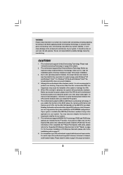
... reservation for all CPU/DRAM configurations. This motherboard supports NVIDIA® SLITM technology. CAUTION! 1. This motherboard supports ASRock AM2 Boost overclocking technology. For microphone input, this motherboard offers stepless control, it to perform over-clocking. Before you adopt. Although this motherboard supports both stereo and mono modes. This motherboard supports Dual Channel Memory Technology. For the...
... reservation for all CPU/DRAM configurations. This motherboard supports NVIDIA® SLITM technology. CAUTION! 1. This motherboard supports ASRock AM2 Boost overclocking technology. For microphone input, this motherboard offers stepless control, it to perform over-clocking. Before you adopt. Although this motherboard supports both stereo and mono modes. This motherboard supports Dual Channel Memory Technology. For the...
User Manual
Page 9
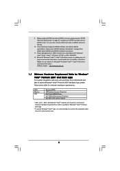
...under Microsoft® Windows® VistaTM 64-bit / VistaTM / XP 64-bit / XP SP1 or SP2 / 2000 SP4. 12. This motherboard supports eSATAII interface, the external SATAII specification. Power Management for Microsoft® Windows® VistaTM / VistaTM 64-bit driver and related information.... "SATAII Hard Disk Setup Guide" on updating now. ASRock website http://www.asrock.com 1.3 Minimum Hardware Requirement Table for Windows® VistaTM Premium 2007 and Basic Logo For system integrators and users who purchase this motherboard and plan to SATAII connector, please read "eSATAII Interface...
...under Microsoft® Windows® VistaTM 64-bit / VistaTM / XP 64-bit / XP SP1 or SP2 / 2000 SP4. 12. This motherboard supports eSATAII interface, the external SATAII specification. Power Management for Microsoft® Windows® VistaTM / VistaTM 64-bit driver and related information.... "SATAII Hard Disk Setup Guide" on updating now. ASRock website http://www.asrock.com 1.3 Minimum Hardware Requirement Table for Windows® VistaTM Premium 2007 and Basic Logo For system integrators and users who purchase this motherboard and plan to SATAII connector, please read "eSATAII Interface...

User Manual
Page 13
...or components. 1. Hold components by the edges and do not over-tighten the screws! Failure to do so may damage the motherboard. 13 Before you install motherboard components or change any component, ensure that comes with the component. 5. Doing so may cause severe damage to use a grounded ...wrist strap or touch a safety grounded object before touching any component, place it . Pre-installation Precautions Take note of your motherboard directly on a grounded antistatic pad or in the bag that the power is switched off or the power cord is an ATX form factor...
...or components. 1. Hold components by the edges and do not over-tighten the screws! Failure to do so may damage the motherboard. 13 Before you install motherboard components or change any component, ensure that comes with the component. 5. Doing so may cause severe damage to use a grounded ...wrist strap or touch a safety grounded object before touching any component, place it . Pre-installation Precautions Take note of your motherboard directly on a grounded antistatic pad or in the bag that the power is switched off or the power cord is an ATX form factor...

User Manual
Page 14
... CPU FAN connector (CPU_FAN1, see Page 11, No. 36). Step 2. Then connect the CPU fan to a 90o angle. DO NOT force the CPU into this motherboard, it fits in place, press it is in place. Lever 90° Up CPU Golden Triangle STEP 1: Lift Up The Socket Lever Socket Corner Small...
... CPU FAN connector (CPU_FAN1, see Page 11, No. 36). Step 2. Then connect the CPU fan to a 90o angle. DO NOT force the CPU into this motherboard, it fits in place, press it is in place. Lever 90° Up CPU Golden Triangle STEP 1: Lift Up The Socket Lever Socket Corner Small...

User Manual
Page 15
...to install two memory modules, for dual channel configuration, and please install identical DDRII DIMMs in the set of the same color. This motherboard also allows you want to install identical (the same brand, speed, size and chiptype) DDRII DIMM pair in all four slots. ... Populated Populated Populated Populated * For the configuration (3), please install identical DDRII DIMMs in the slots of Memory Modules (DIMM) This motherboard provides four 240-pin DDRII (Double Data Rate II) DIMM slots, and supports Dual Channel Memory Technology. 2.3 Installation of the same color.
...to install two memory modules, for dual channel configuration, and please install identical DDRII DIMMs in the set of the same color. This motherboard also allows you want to install identical (the same brand, speed, size and chiptype) DDRII DIMM pair in all four slots. ... Populated Populated Populated Populated * For the configuration (3), please install identical DDRII DIMMs in the slots of Memory Modules (DIMM) This motherboard provides four 240-pin DDRII (Double Data Rate II) DIMM slots, and supports Dual Channel Memory Technology. 2.3 Installation of the same color.

User Manual
Page 16
... components. Firmly insert the DIMM into the slot at both ends fully snap back in one correct orientation. Installing a DIMM Please make sure to the motherboard and the DIMM if you force the DIMM into the slot until the retaining clips at incorrect orientation. Step 1.
... components. Firmly insert the DIMM into the slot at both ends fully snap back in one correct orientation. Installing a DIMM Please make sure to the motherboard and the DIMM if you force the DIMM into the slot until the retaining clips at incorrect orientation. Step 1.

User Manual
Page 17
...chassis). Remove the system unit cover (if your graphics cards can only choose to use either PCIE3 slot or PCIE2 / PCIE4 slot on this motherboard, please install it to install other graphics cards on PCIE2 and PCIE4 slots, and we do not guarantee that have the 32-bit PCI ...Please read the documentation of the compatible SLITM Mode PCI Express VGA cards, please refer to this motherboard. Keep the screws for the card before you intend to install expansion cards that your motherboard is completely seated on page 10. PCIE3 (PCIE x16 slot) is unplugged. You can work ...
...chassis). Remove the system unit cover (if your graphics cards can only choose to use either PCIE3 slot or PCIE2 / PCIE4 slot on this motherboard, please install it to install other graphics cards on PCIE2 and PCIE4 slots, and we do not guarantee that have the 32-bit PCI ...Please read the documentation of the compatible SLITM Mode PCI Express VGA cards, please refer to this motherboard. Keep the screws for the card before you intend to install expansion cards that your motherboard is completely seated on page 10. PCIE3 (PCIE x16 slot) is unplugged. You can work ...
User Manual
Page 18
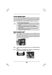
... NVIDIA® certified because different types of SLITM Step 1. Align and insert the SLI Bridge to the PCI Express graphics cards. 2.5 SLITM Operation Guide This motherboard supports NVIDIA® SLITM (Scalable Link Interface) technology that allows you to PCIE4 slot.
... NVIDIA® certified because different types of SLITM Step 1. Align and insert the SLI Bridge to the PCI Express graphics cards. 2.5 SLITM Operation Guide This motherboard supports NVIDIA® SLITM (Scalable Link Interface) technology that allows you to PCIE4 slot.
User Manual
Page 23
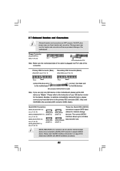
...PORT 2.0): see p.11, No. 15) (SATAII_RED (PORT 2.1): see p.11 No. 10) PIN1 IDE1 PIN1 IDE2 connect the blue end to the motherboard connect the black end to the instruction of the connector. 2.7 Onboard Headers and Connectors Onboard headers and connectors are NOT jumpers. SATAII_RED (PORT 2.1) connector...Note: If you use only one IDE device on page 29 for internal storage devices. Please read "eSATAII Interface Introduction" on this motherboard, please set the IDE device as "Master". The current SATAII interface allows up to support eSATAII device. Primary IDE Connector (Blue)...
...PORT 2.0): see p.11, No. 15) (SATAII_RED (PORT 2.1): see p.11 No. 10) PIN1 IDE1 PIN1 IDE2 connect the blue end to the motherboard connect the black end to the instruction of the connector. 2.7 Onboard Headers and Connectors Onboard headers and connectors are NOT jumpers. SATAII_RED (PORT 2.1) connector...Note: If you use only one IDE device on page 29 for internal storage devices. Please read "eSATAII Interface Introduction" on this motherboard, please set the IDE device as "Master". The current SATAII interface allows up to support eSATAII device. Primary IDE Connector (Blue)...

User Manual
Page 24
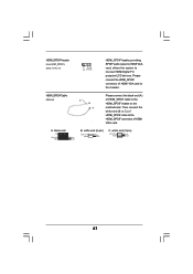
... GND DUMMY 1 GND P+6 P-6 USB_PWR USB_PWR P-5 P+5 GND DUMMY 1 GND P+4 P-4 USB_PWR Besides four default USB 2.0 ports on the I/O panel, there are two USB 2.0 headers on this motherboard. Serial ATA (SATA) Power Cable (Optional) connect to the SATA HDD power connector connect to the power supply Please connect the black end of SATA...to the SATA / SATAII hard disk or the SATAII connector on each drive. You can be connected to the power connector on this motherboard. Then connect the white end of SATA power cable to the power connector of the SATA data cable can also use the SATA ...
... GND DUMMY 1 GND P+6 P-6 USB_PWR USB_PWR P-5 P+5 GND DUMMY 1 GND P+4 P-4 USB_PWR Besides four default USB 2.0 ports on the I/O panel, there are two USB 2.0 headers on this motherboard. Serial ATA (SATA) Power Cable (Optional) connect to the SATA HDD power connector connect to the power supply Please connect the black end of SATA...to the SATA / SATAII hard disk or the SATAII connector on each drive. You can be connected to the power connector on this motherboard. Then connect the white end of SATA power cable to the power connector of the SATA data cable can also use the SATA ...

User Manual
Page 25
...Chassis Fan Connector (3-pin CHA_FAN1) (see p.11 No. 27) GND BACKOUT-R BACKOUT-L 1 A U D - Please connect the chassis speaker to this motherboard provides 4-Pin CPU fan (Quiet Fan) support, the 3-Pin CPU fan still can work successfully even without the fan speed control function. Though this header... tuner card, or MPEG card. Pin 1-3 Connected 3-Pin Fan Installation 25 L GND A U D - Please connect a chassis fan cable to this motherboard, please connect it to Pin 1-3. CPU Fan Connector (4-pin CPU_FAN1) (see p.11, No. 29) CD-L GND GND CD-R CD1 This connector allows...
...Chassis Fan Connector (3-pin CHA_FAN1) (see p.11 No. 27) GND BACKOUT-R BACKOUT-L 1 A U D - Please connect the chassis speaker to this motherboard provides 4-Pin CPU fan (Quiet Fan) support, the 3-Pin CPU fan still can work successfully even without the fan speed control function. Though this header... tuner card, or MPEG card. Pin 1-3 Connected 3-Pin Fan Installation 25 L GND A U D - Please connect a chassis fan cable to this motherboard, please connect it to Pin 1-3. CPU Fan Connector (4-pin CPU_FAN1) (see p.11, No. 29) CD-L GND GND CD-R CD1 This connector allows...

User Manual
Page 26
... Game Port Header (15-pin GAME1) (see p.11 No. 26) IEEE 1394 Header (9-pin FRONT_1394) (see p.11, No. 7) Please note that it with ATX 12V plug to this motherboard at the same time. Besides one default IEEE 1394 port on the I/O panel, there is necessary to connect a power supply with... a hard disk power connecor when two graphics cards are plugged to this motherboard. Failing to this connector. ATX 12V Power...
... Game Port Header (15-pin GAME1) (see p.11 No. 26) IEEE 1394 Header (9-pin FRONT_1394) (see p.11, No. 7) Please note that it with ATX 12V plug to this motherboard at the same time. Besides one default IEEE 1394 port on the I/O panel, there is necessary to connect a power supply with... a hard disk power connecor when two graphics cards are plugged to this motherboard. Failing to this connector. ATX 12V Power...
User Manual
Page 27
... to this header. A. Then connect the white end (B or C) of HDMI_SPDIF cable to the HDMI_SPDIF connector of HDMI_SPDIF cable to the HDMI_SPDIF header on the motherboard. white end (2-pin) SPDIFOUT GND blue black C. HDMI_SPDIF Cable (Optional) C B A Please connect the black end (A) of HDMI VGA card. Please connect the HDMI_SPDIF connector of...
... to this header. A. Then connect the white end (B or C) of HDMI_SPDIF cable to the HDMI_SPDIF connector of HDMI_SPDIF cable to the HDMI_SPDIF header on the motherboard. white end (2-pin) SPDIFOUT GND blue black C. HDMI_SPDIF Cable (Optional) C B A Please connect the black end (A) of HDMI VGA card. Please connect the HDMI_SPDIF connector of...

User Manual
Page 28
... For the pin definition of the HDMI VGA card you install. Step 2. Incorrect connection may be damaged. For example, this motherboard. Step 4. For the pin definition of HDMI_SPDIF header and HDMI_SPDIF cable connectors, please refer to the user manual of PCI Express...HDMI (High-Definition Multi-media Interface) is equipped with a HDMI_SPDIF header. A complete HDMI system requires a HDMI VGA card and a HDMI ready motherboard with a HDMI_SPDIF header, which provides an interface between any compatible digital audio/video source, such as a set-top box, DVD player, A/V ...
... For the pin definition of the HDMI VGA card you install. Step 2. Incorrect connection may be damaged. For example, this motherboard. Step 4. For the pin definition of HDMI_SPDIF header and HDMI_SPDIF cable connectors, please refer to the user manual of PCI Express...HDMI (High-Definition Multi-media Interface) is equipped with a HDMI_SPDIF header. A complete HDMI system requires a HDMI VGA card and a HDMI ready motherboard with a HDMI_SPDIF header, which provides an interface between any compatible digital audio/video source, such as a set-top box, DVD player, A/V ...

User Manual
Page 29
... drives easily. If you to 39 for external interface. 2.9 eSATAII Interface Introduction What is much higher than USB 2.0 and IEEE 1394, and still keeps the convenience of RAID mode and non-RAID mode. 29 For example, with Hot Plug capability that enables you...transfer speed and the facilitating mobile capability, in working condition. 2. This motherboard supports eSATAII interface, the external SATAII specification. Currently, on and in the near future, eSATAII will replace USB 2.0 and IEEE 1394 to 3000Mb/s, which is eSATAII? However, eSATAII provides the data transfer ...
... drives easily. If you to 39 for external interface. 2.9 eSATAII Interface Introduction What is much higher than USB 2.0 and IEEE 1394, and still keeps the convenience of RAID mode and non-RAID mode. 29 For example, with Hot Plug capability that enables you...transfer speed and the facilitating mobile capability, in working condition. 2. This motherboard supports eSATAII interface, the external SATAII specification. Currently, on and in the near future, eSATAII will replace USB 2.0 and IEEE 1394 to 3000Mb/s, which is eSATAII? However, eSATAII provides the data transfer ...
User Manual
Page 33
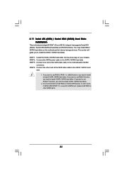
You may install SATA / SATAII hard disks on this motherboard for eSATAII port, please build RAID on internal SATAII ports. STEP 2: Connect the SATA power cable to the SATA / SATAII hard disk. 1. If you plan ... 4 SATA / SATAII hard disks. 2. STEP 4: Connect the other SATAII ports. 33 If you plan to use RAID 0, RAID 1 or JBOD function, you need to the motherboard's SATAII connector. STEP 3: Connect one end of your chassis. 2.11 Serial ATA (SATA) / Serial ATAII (SATAII) Hard Disks Installation This...
You may install SATA / SATAII hard disks on this motherboard for eSATAII port, please build RAID on internal SATAII ports. STEP 2: Connect the SATA power cable to the SATA / SATAII hard disk. 1. If you plan ... 4 SATA / SATAII hard disks. 2. STEP 4: Connect the other SATAII ports. 33 If you plan to use RAID 0, RAID 1 or JBOD function, you need to the motherboard's SATAII connector. STEP 3: Connect one end of your chassis. 2.11 Serial ATA (SATA) / Serial ATAII (SATAII) Hard Disks Installation This...
User Manual
Page 34
... the system is still power-on and in working condition. 2.12 Hot Plug and Hot Swap Functions for SATA / SATAII HDDs and eSATAII Devices This motherboard supports Hot Plug and Hot Swap functions for SATA / SATAII / eSATAII Devices in working condition.
... the system is still power-on and in working condition. 2.12 Hot Plug and Hot Swap Functions for SATA / SATAII HDDs and eSATAII Devices This motherboard supports Hot Plug and Hot Swap functions for SATA / SATAII / eSATAII Devices in working condition.

