User Manual
Page 3
... 2.11 Serial ATA (SATA) / Serial ATAII (SATAII) Hard Disks Installation 33 2.12 Hot Plug and Hot Swap Functions for SLITM Mode 10 1.5 Motherboard Layout 11 1.6 ASRock 1394_eSATAII I/O Plus 12 2 . Contents 1 . BIOS SETUP UTILITY 40 3.1 Introduction 40 3.1.1 BIOS Menu Bar 40 3.1.2 Navigation Keys 41 3
... 2.11 Serial ATA (SATA) / Serial ATAII (SATAII) Hard Disks Installation 33 2.12 Hot Plug and Hot Swap Functions for SLITM Mode 10 1.5 Motherboard Layout 11 1.6 ASRock 1394_eSATAII I/O Plus 12 2 . Contents 1 . BIOS SETUP UTILITY 40 3.1 Introduction 40 3.1.1 BIOS Menu Bar 40 3.1.2 Navigation Keys 41 3

User Manual
Page 5
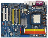
.... 1. Because the motherboard specifications and the BIOS software might be available on ASRock website as well. In case any modifications of the Support CD. ASRock website http://www.asrock.com 1.1 Package Contents 1 x ASRock ALiveNF5SLI-1394 Motherboard (ATX Form Factor: 12.0-in x 9.0-in, 30.5 cm x 22.9 cm) 1 x ASRock SLI Bridge 1 x ASRock ALiveNF5SLI-1394 Quick Installation Guide 1 x ASRock ALiveNF5SLI-1394 Support CD 1 x Ultra ATA 66/100...
.... 1. Because the motherboard specifications and the BIOS software might be available on ASRock website as well. In case any modifications of the Support CD. ASRock website http://www.asrock.com 1.1 Package Contents 1 x ASRock ALiveNF5SLI-1394 Motherboard (ATX Form Factor: 12.0-in x 9.0-in, 30.5 cm x 22.9 cm) 1 x ASRock SLI Bridge 1 x ASRock ALiveNF5SLI-1394 Quick Installation Guide 1 x ASRock ALiveNF5SLI-1394 Support CD 1 x Ultra ATA 66/100...

User Manual
Page 7
...9) - 1 x eSATAII 3.0Gb/s connector (shared with 1 SATAII connector), supports NCQ and "Hot Plug" functions (see CAUTION 11) - 4Mb AMI BIOS - Supports "Plug and Play" - SMBIOS 2.3.1 Support - Front panel audio connector - 2 x USB 2.0 headers (support 4 USB 2.0 ports) (... 4 x IDE devices) - 1 x Floppy connector - 1 x IR header - 1 x Game header - 1 x HDMI_SPDIF header - 1 x IEEE 1394 header - AMI Legal BIOS - CPU Ambient Temperature Sensing - Supports jumperfree - ACPI 1.1 Compliance Wake Up Events - Chassis Temperature Sensing - Microsoft® Windows® 2000 / XP /...
...9) - 1 x eSATAII 3.0Gb/s connector (shared with 1 SATAII connector), supports NCQ and "Hot Plug" functions (see CAUTION 11) - 4Mb AMI BIOS - Supports "Plug and Play" - SMBIOS 2.3.1 Support - Front panel audio connector - 2 x USB 2.0 headers (support 4 USB 2.0 ports) (... 4 x IDE devices) - 1 x Floppy connector - 1 x IR header - 1 x Game header - 1 x HDMI_SPDIF header - 1 x IEEE 1394 header - AMI Legal BIOS - CPU Ambient Temperature Sensing - Supports jumperfree - ACPI 1.1 Compliance Wake Up Events - Chassis Temperature Sensing - Microsoft® Windows® 2000 / XP /...
User Manual
Page 8
... system. 7. For Windows® XP 64-bit and Windows® VistaTM 64bit with overclocking, including adjusting the setting in the BIOS setup, the memory performance will overclock the chipset/CPU reference clock. Before you implement Dual Channel Memory Technology, make sure to read.... For audio output, this motherboard supports both stereo and mono modes. This motherboard supports Dual Channel Memory Technology. This motherboard supports ASRock AM2 Boost overclocking technology. If your system is unstable after AM2 Boost function is a certain risk involved with 64-bit CPU,...
... system. 7. For Windows® XP 64-bit and Windows® VistaTM 64bit with overclocking, including adjusting the setting in the BIOS setup, the memory performance will overclock the chipset/CPU reference clock. Before you implement Dual Channel Memory Technology, make sure to read.... For audio output, this motherboard supports both stereo and mono modes. This motherboard supports Dual Channel Memory Technology. This motherboard supports ASRock AM2 Boost overclocking technology. If your system is unstable after AM2 Boost function is a certain risk involved with 64-bit CPU,...

User Manual
Page 12
1.6 ASRock 1394_eSATAII I/O Plus 1 PS/2 Mouse Port (Green) 2 Parallel Port 3 IEEE 1394 Port 4 RJ-45 Port 5 Side Speaker (Gray) 6 Rear Speaker (Black) 7 Central / Bass (Orange) 8 Line In (Light Blue) * 9 Front Speaker (Lime) 10 Microphone... Output Channels Front Speaker Rear Speaker (No. 9) (No. 6) Central / Bass Side Speaker (No. 7) (No. 5) 2 V -- -- -- 4 V -- -- TABLE for connection details in BIOS setup first. 12 V V 8 V V V V * If you install Windows® VistaTM or VistaTM 64-bit OS, please correctly select the channel of the audio source (2-channel, 4-channel...
1.6 ASRock 1394_eSATAII I/O Plus 1 PS/2 Mouse Port (Green) 2 Parallel Port 3 IEEE 1394 Port 4 RJ-45 Port 5 Side Speaker (Gray) 6 Rear Speaker (Black) 7 Central / Bass (Orange) 8 Line In (Light Blue) * 9 Front Speaker (Lime) 10 Microphone... Output Channels Front Speaker Rear Speaker (No. 9) (No. 6) Central / Bass Side Speaker (No. 7) (No. 5) 2 V -- -- -- 4 V -- -- TABLE for connection details in BIOS setup first. 12 V V 8 V V V V * If you install Windows® VistaTM or VistaTM 64-bit OS, please correctly select the channel of the audio source (2-channel, 4-channel...

User Manual
Page 22
... "Open". When the jumper cap is placed on CLRCMOS1 for 15 seconds, use a jumper cap to clear the CMOS when you just finish updating the BIOS, you must boot up events. JR1 JL1 Jumper (see p.11, No. 17) 1_2 2_3 Default Clear CMOS Note: CLRCMOS1 allows you update the...
... "Open". When the jumper cap is placed on CLRCMOS1 for 15 seconds, use a jumper cap to clear the CMOS when you just finish updating the BIOS, you must boot up events. JR1 JL1 Jumper (see p.11, No. 17) 1_2 2_3 Default Clear CMOS Note: CLRCMOS1 allows you update the...

User Manual
Page 29
...higher than USB 2.0 and IEEE 1394, and still keeps the convenience of your SATAII hard disk. For example, with eSATAII devices. NOTE: 1. Therefore, you still want to use the eSATAII HDD as an OS disk, please set "SATA Operation Mode" option in BIOS setup to RAID mode and enable...2.0 is power-off. 3. eSATAII allows you want to use eSATAII function in working condition. 2. If you set "SATA Operation Mode" option in BIOS setup to non-RAID mode, Hot Plug function is eSATAII? 2.9 eSATAII Interface Introduction What is not supported with eSATAII interface, you want to add ...
...higher than USB 2.0 and IEEE 1394, and still keeps the convenience of your SATAII hard disk. For example, with eSATAII devices. NOTE: 1. Therefore, you still want to use the eSATAII HDD as an OS disk, please set "SATA Operation Mode" option in BIOS setup to RAID mode and enable...2.0 is power-off. 3. eSATAII allows you want to use eSATAII function in working condition. 2. If you set "SATA Operation Mode" option in BIOS setup to non-RAID mode, Hot Plug function is eSATAII? 2.9 eSATAII Interface Introduction What is not supported with eSATAII interface, you want to add ...
User Manual
Page 37
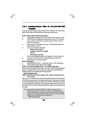
... system, please insert the support CD to your Windows® 2000 optical disk is supposed to include SP4. Therefore, the drivers you to change the BIOS setting.
... system, please insert the support CD to your Windows® 2000 optical disk is supposed to include SP4. Therefore, the drivers you to change the BIOS setting.
User Manual
Page 38
...Driver Diskette. During POST at the beginning of Windows® setup, press F6 to install a third-party RAID driver. A. Please select CD- Enter BIOS SETUP UTILITY Advanced screen IDE Configuration. NOTE. After step 1, 2, 3, you can start to configure RAID function, you need to set the RAID ... Before you start to install Windows® 2000 / Windows® XP / Windows® XP 64-bit OS on your system. Insert the ASRock Support CD into your optical drive to boot your SATA / SATAII HDDs with RAID functions, please follow below steps. ROM as the boot device. ...
...Driver Diskette. During POST at the beginning of Windows® setup, press F6 to install a third-party RAID driver. A. Please select CD- Enter BIOS SETUP UTILITY Advanced screen IDE Configuration. NOTE. After step 1, 2, 3, you can start to configure RAID function, you need to set the RAID ... Before you start to install Windows® 2000 / Windows® XP / Windows® XP 64-bit OS on your system. Insert the ASRock Support CD into your optical drive to boot your SATA / SATAII HDDs with RAID functions, please follow below steps. ROM as the boot device. ...
User Manual
Page 39
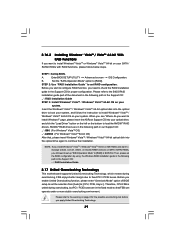
page, please insert the ASRock Support CD into your SATA / SATAII HDDs with RAID functions, please follow the instruction to the BIOS RAID installation guide part of BIOS setup to set up "SATA Operation Mode" to [RAID] in the fixed mode so that , please insert Windows® ... This motherboard supports Untied Overclocking Technology, which means during overclocking, FSB enjoys better margin due to fixed PCI / PCIE buses. Enter BIOS SETUP UTILITY Advanced screen IDE Configuration. STEP 2: Use "RAID Installation Guide" to set the RAID configuration by using the Windows RAID ...
page, please insert the ASRock Support CD into your SATA / SATAII HDDs with RAID functions, please follow the instruction to the BIOS RAID installation guide part of BIOS setup to set up "SATA Operation Mode" to [RAID] in the fixed mode so that , please insert Windows® ... This motherboard supports Untied Overclocking Technology, which means during overclocking, FSB enjoys better margin due to fixed PCI / PCIE buses. Enter BIOS SETUP UTILITY Advanced screen IDE Configuration. STEP 2: Use "RAID Installation Guide" to set the RAID configuration by using the Windows RAID ...

User Manual
Page 40
... is constantly being updated, the following selections: Main To set up the system time/date information Advanced To set up the advanced BIOS features H/W Monitor To display current hardware status Boot To set up the default system device to locate and load the Operating System Security To set ...up the computer. You may also restart by pressing the reset button on the motherboard stores the BIOS SETUP UTILITY. The Flash Memory on the system chassis. Please press during the Power-On-Self-Test (POST) to configure your screen...
... is constantly being updated, the following selections: Main To set up the system time/date information Advanced To set up the advanced BIOS features H/W Monitor To display current hardware status Boot To set up the default system device to locate and load the Operating System Security To set ...up the computer. You may also restart by pressing the reset button on the motherboard stores the BIOS SETUP UTILITY. The Flash Memory on the system chassis. Please press during the Power-On-Self-Test (POST) to configure your screen...

User Manual
Page 41
... UTILITY Main Advanced H/W Monitor Boot Security Exit System Overview System Time System Date [17:00:09] [Sat 06/23/2007] BIOS Version : ALiveNF5SLI-1394 BIOS P1.00 Processor Type : AMD Athlon(tm) 64 Processor 3500+ (64bit) Processor Speed : 2200 MHz Microcode Update : 40FF2/0 L1 Cache Size : 128KB L2 ...SHIFT-TAB] to specify the system time. 3.1.2 Navigation Keys Please check the following table for all the settings To save changes and exit the BIOS SETUP UTILITY To jump to configure system Time. +Tab F1 F9 F10 ESC Select Screen Select Item Change Field Select Field General Help Load ...
... UTILITY Main Advanced H/W Monitor Boot Security Exit System Overview System Time System Date [17:00:09] [Sat 06/23/2007] BIOS Version : ALiveNF5SLI-1394 BIOS P1.00 Processor Type : AMD Athlon(tm) 64 Processor 3500+ (64bit) Processor Speed : 2200 MHz Microcode Update : 40FF2/0 L1 Cache Size : 128KB L2 ...SHIFT-TAB] to specify the system time. 3.1.2 Navigation Keys Please check the following table for all the settings To save changes and exit the BIOS SETUP UTILITY To jump to configure system Time. +Tab F1 F9 F10 ESC Select Screen Select Item Change Field Select Field General Help Load ...

User Manual
Page 42
... malfunction. 3.3 Advanced Screen In this section, you will enable ASRock AM2 Boost function, which will improve the memory performance. Please refer to malfunction. 3.3.1 CPU Configuration BIOS SETUP UTILITY Advanced CPU Configuration AM2 Boost Overclock Mode CPU Frequency ..., Chipset Configuration, ACPI Configuration, IDE Configuration, PCIPnP Configuration, Floppy Configuration, SuperIO Configuration, and USB Configuration. Main BIOS SETUP UTILITY Advanced H/W Monitor Boot Security Exit Advanced Settings WARNING : Setting wrong values in Setup. +F1 F9 F10...
... malfunction. 3.3 Advanced Screen In this section, you will enable ASRock AM2 Boost function, which will improve the memory performance. Please refer to malfunction. 3.3.1 CPU Configuration BIOS SETUP UTILITY Advanced CPU Configuration AM2 Boost Overclock Mode CPU Frequency ..., Chipset Configuration, ACPI Configuration, IDE Configuration, PCIPnP Configuration, Floppy Configuration, SuperIO Configuration, and USB Configuration. Main BIOS SETUP UTILITY Advanced H/W Monitor Boot Security Exit Advanced Settings WARNING : Setting wrong values in Setup. +F1 F9 F10...

User Manual
Page 44
.../voltage. The default value is [Auto]. The default value is [Auto]. The default value is [Auto]. 44 Configuration options: [Auto], [3CLK], [4CLK], [5CLK], and [6CLK]. BIOS SETUP UTILITY Advanced CPU Configuration AM2 Boost Overclock Mode CPU Frequency (MHz) PCIE Frequency (MHz) Boot Failure Guard CPU Spread Spectrum PCIE Spread Spectrum SATA...
.../voltage. The default value is [Auto]. The default value is [Auto]. The default value is [Auto]. 44 Configuration options: [Auto], [3CLK], [4CLK], [5CLK], and [6CLK]. BIOS SETUP UTILITY Advanced CPU Configuration AM2 Boost Overclock Mode CPU Frequency (MHz) PCIE Frequency (MHz) Boot Failure Guard CPU Spread Spectrum PCIE Spread Spectrum SATA...
User Manual
Page 46
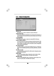
...[Auto], [8 Bit], and [16 Bit]. The default value is [PCI]. It allows you selecting CPU to enable or disable the onboard IEEE 1394 feature. NB Link Speed This feature allows you to NB link width. If you selecting CPU to select the type of Primary VGA in case...Bus scanning order while searching for the onboard UAA Audio feature. The default value is plugged. 3.3.2 Chipset Configuration BIOS SETUP UTILITY Advanced Chipset Settings Onboard LAN OnBoard UAA Audio Onboard IEEE 1394 Primary Graphics Adapter CPU-NB Link Speed CPU-NB Link Width DRAM Voltage NBCORE Voltage [Enabled] [Auto] ...
...[Auto], [8 Bit], and [16 Bit]. The default value is [PCI]. It allows you selecting CPU to enable or disable the onboard IEEE 1394 feature. NB Link Speed This feature allows you to NB link width. If you selecting CPU to select the type of Primary VGA in case...Bus scanning order while searching for the onboard UAA Audio feature. The default value is plugged. 3.3.2 Chipset Configuration BIOS SETUP UTILITY Advanced Chipset Settings Onboard LAN OnBoard UAA Audio Onboard IEEE 1394 Primary Graphics Adapter CPU-NB Link Speed CPU-NB Link Width DRAM Voltage NBCORE Voltage [Enabled] [Auto] ...

User Manual
Page 47
..." will enable this item to enable or disable Away Mode support under Windows® XP Media Center OS. If [Power On] is [Disabled]. 3.3.3 ACPI Configuration BIOS SETUP UTILITY Advanced ACPI Settings Suspend To RAM Away Mode Support Restore on STR resume. (STR refers to suspend to RAM.) Away Mode Support Use...
..." will enable this item to enable or disable Away Mode support under Windows® XP Media Center OS. If [Power On] is [Disabled]. 3.3.3 ACPI Configuration BIOS SETUP UTILITY Advanced ACPI Settings Suspend To RAM Away Mode Support Restore on STR resume. (STR refers to suspend to RAM.) Away Mode Support Use...
User Manual
Page 48
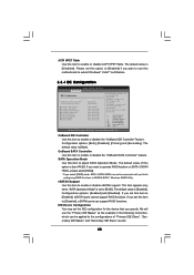
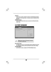
...the following instruction, which can be accessed until you set this motherboard to submit Windows® VistaTM certification. 3.3.4 IDE Configuration BIOS SETUP UTILITY Advanced IDE Configuration OnBoard IDE Controller OnBoard SATA Controller SATA Operation Mode Primary IDE Master Primary IDE Slave Secondary IDE ...Both]. We will use this option to [Enabled] if you plan to use the "Primary IDE Master" as the example in NVIDIA BIOS / Windows RAID Utility. OnBoard SATA Controller Use this item to enable or disable the "OnBoard SATA Controller" feature. SATA Operation Mode ...
...the following instruction, which can be accessed until you set this motherboard to submit Windows® VistaTM certification. 3.3.4 IDE Configuration BIOS SETUP UTILITY Advanced IDE Configuration OnBoard IDE Controller OnBoard SATA Controller SATA Operation Mode Primary IDE Master Primary IDE Slave Secondary IDE ...Both]. We will use this option to [Enabled] if you plan to use the "Primary IDE Master" as the example in NVIDIA BIOS / Windows RAID Utility. OnBoard SATA Controller Use this item to enable or disable the "OnBoard SATA Controller" feature. SATA Operation Mode ...

User Manual
Page 49
...and [ARMD]. [Not Installed]: Select [Not Installed] to disable the use a disk utility, such as MO. After selecting the hard disk information into BIOS, use of IDE device. [Auto]: Select [Auto] to partition and format the new IDE hard disk drives. Block (Multi-Sector Transfer) The default ... ESC Select Screen Select Item Change Option General Help Load Defaults Save and Exit Exit v02.54 (C) Copyright 1985-2003, American Megatrends, Inc. BIOS SETUP UTILITY Advanced IDE Master Device Vendor Size LBA Mode Block Mode PIO Mode Async DMA Ultra DMA S.M.A.R.T. :Hard Disk :MAXTOR 6L080J4 :80...
...and [ARMD]. [Not Installed]: Select [Not Installed] to disable the use a disk utility, such as MO. After selecting the hard disk information into BIOS, use of IDE device. [Auto]: Select [Auto] to partition and format the new IDE hard disk drives. Block (Multi-Sector Transfer) The default ... ESC Select Screen Select Item Change Option General Help Load Defaults Save and Exit Exit v02.54 (C) Copyright 1985-2003, American Megatrends, Inc. BIOS SETUP UTILITY Advanced IDE Master Device Vendor Size LBA Mode Block Mode PIO Mode Async DMA Ultra DMA S.M.A.R.T. :Hard Disk :MAXTOR 6L080J4 :80...
User Manual
Page 50
...: [Disabled], [Auto], [Enabled]. 32Bit Data Transfer Use this item to enable 32-bit access to maximize the IDE hard disk data transfer rate. 3.3.5 PCIPnP Configuration BIOS SETUP UTILITY Advanced Advanced PCI / PnP Settings PCI Latency Timer PCI IDE BusMaster [32] [Enabled] Value in this item to malfunction.
...: [Disabled], [Auto], [Enabled]. 32Bit Data Transfer Use this item to enable 32-bit access to maximize the IDE hard disk data transfer rate. 3.3.5 PCIPnP Configuration BIOS SETUP UTILITY Advanced Advanced PCI / PnP Settings PCI Latency Timer PCI IDE BusMaster [32] [Enabled] Value in this item to malfunction.
User Manual
Page 51
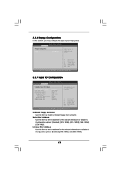
... and [2E8 / IRQ3]. 51 3.3.6 Floppy Configuration In this item to set the address for the onboard serial port or disable it . BIOS SETUP UTILITY Advanced Floppy Configuration Floppy A [1.44 MB 312"] Select the type of your floppy drive. OnBoard Floppy Controller Use this item to...General Help Load Defaults Save and Exit Exit v02.54 (C) Copyright 1985-2003, American Megatrends, Inc. 3.3.7 Super IO Configuration BIOS SETUP UTILITY Advanced Configure Super IO Chipset OnBoard Floppy Controller Serial Port Address Infrared Port Address Parallel Port Address Parallel Port Mode ...
... and [2E8 / IRQ3]. 51 3.3.6 Floppy Configuration In this item to set the address for the onboard serial port or disable it . BIOS SETUP UTILITY Advanced Floppy Configuration Floppy A [1.44 MB 312"] Select the type of your floppy drive. OnBoard Floppy Controller Use this item to...General Help Load Defaults Save and Exit Exit v02.54 (C) Copyright 1985-2003, American Megatrends, Inc. 3.3.7 Super IO Configuration BIOS SETUP UTILITY Advanced Configure Super IO Chipset OnBoard Floppy Controller Serial Port Address Infrared Port Address Parallel Port Address Parallel Port Mode ...


