RAID Installation Guide
Page 2
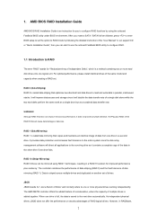
..." stands for "Redundant Array of the data in a RAID 10 solution for you to configure RAID functions by following the detailed instruction of the "User Manual" in our support CD or "Quick Installation Guide", then you make a SATA / SATAII driver diskette, press to enter BIOS setup to set the option to...
..." stands for "Redundant Array of the data in a RAID 10 solution for you to configure RAID functions by following the detailed instruction of the "User Manual" in our support CD or "Quick Installation Guide", then you make a SATA / SATAII driver diskette, press to enter BIOS setup to set the option to...
RAID Installation Guide
Page 8
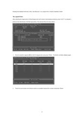
Two Logical Drives After selecting the logical drive in our support CD or "Quick Installation Guide". Press the up and down arrow keys to the first logical drive. Enter the desired capacity (MB) for the first logical drive and press . The Define LD Menu displays again. 2. Then please follow the steps below. 1. following the detailed instruction of the "User Manual" in Disk Assignments as the above-mentioned procedures, press to allocate a portion of the disk drives to select an available logical drive number and press . 8
Two Logical Drives After selecting the logical drive in our support CD or "Quick Installation Guide". Press the up and down arrow keys to the first logical drive. Enter the desired capacity (MB) for the first logical drive and press . The Define LD Menu displays again. 2. Then please follow the steps below. 1. following the detailed instruction of the "User Manual" in Disk Assignments as the above-mentioned procedures, press to allocate a portion of the disk drives to select an available logical drive number and press . 8
RAID Installation Guide
Page 9
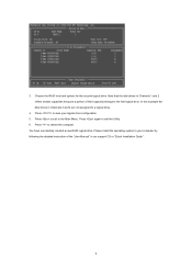
... drives in our support CD or "Quick Installation Guide". 9 Note that the disk drives in Channels 1 and 2 reflect smaller capacities because a portion of the "User Manual" in Channels 3 and 4 are not assigned to the Main Menu. Press to exit to a logical drive. 4.
... drives in our support CD or "Quick Installation Guide". 9 Note that the disk drives in Channels 1 and 2 reflect smaller capacities because a portion of the "User Manual" in Channels 3 and 4 are not assigned to the Main Menu. Press to exit to a logical drive. 4.

RAID Installation Guide
Page 13
... Port number 25902 • Add to launch RAIDXpert amd Together, your browser: 1. In the Browser address field, type the entry explained below. Or, log on manually with your entry looks like this: http://127.0.0.1:25902/ati or http://localhost:25902/ati 2.6 Secure Connection RAIDXpert uses a secure HTTP connection https:// 13
... Port number 25902 • Add to launch RAIDXpert amd Together, your browser: 1. In the Browser address field, type the entry explained below. Or, log on manually with your entry looks like this: http://127.0.0.1:25902/ati or http://localhost:25902/ati 2.6 Secure Connection RAIDXpert uses a secure HTTP connection https:// 13
User Manual
Page 1
A780FullDisplayPort User Manual Version 1.2 Published March 2008 Copyright©2008 ASRock INC. All rights reserved. 1
A780FullDisplayPort User Manual Version 1.2 Published March 2008 Copyright©2008 ASRock INC. All rights reserved. 1
User Manual
Page 2
... damages (including damages for any errors or omissions that may cause undesired operation. With respect to the contents of this manual, ASRock does not provide warranty of any kind, either expressed or implied, including but not limited to the implied warranties or conditions..., without intent to change without written consent of ASRock Inc. Products and corporate names appearing in this manual. "Perchlorate Material-special handling may apply, see www.dtsc.ca.gov/hazardouswaste/perchlorate" ASRock Website: http://www.asrock.com 2 CALIFORNIA, USA ONLY The Lithium battery adopted...
... damages (including damages for any errors or omissions that may cause undesired operation. With respect to the contents of this manual, ASRock does not provide warranty of any kind, either expressed or implied, including but not limited to the implied warranties or conditions..., without intent to change without written consent of ASRock Inc. Products and corporate names appearing in this manual. "Perchlorate Material-special handling may apply, see www.dtsc.ca.gov/hazardouswaste/perchlorate" ASRock Website: http://www.asrock.com 2 CALIFORNIA, USA ONLY The Lithium battery adopted...
User Manual
Page 5
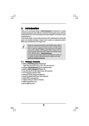
... will be subject to this manual will be available on ASRock website as well. It delivers excellent performance with robust design conforming to ASRock's commitment to -HDMI Converter 5 www.asrock.com/support/index.asp 1.1 Package Contents 1 x ASRock A780FullDisplayPort Motherboard (Micro ATX Form Factor: 9.6-in x 9.6-in, 24.4 cm x 24.4 cm) 1 x ASRock A780FullDisplayPort Quick Installation Guide 2 x ASRock A780FullDisplayPort Support CD 1 x Ultra ATA...
... will be subject to this manual will be available on ASRock website as well. It delivers excellent performance with robust design conforming to ASRock's commitment to -HDMI Converter 5 www.asrock.com/support/index.asp 1.1 Package Contents 1 x ASRock A780FullDisplayPort Motherboard (Micro ATX Form Factor: 9.6-in x 9.6-in, 24.4 cm x 24.4 cm) 1 x ASRock A780FullDisplayPort Quick Installation Guide 2 x ASRock A780FullDisplayPort Support CD 1 x Ultra ATA...
User Manual
Page 17
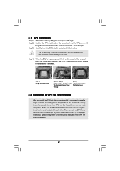
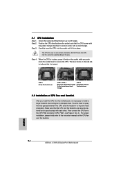
... Step 1. Step 4. Carefully insert the CPU into the socket to indicate that it is necessary to install a larger heatsink and cooling fan to the instruction manuals of the pins. Position the CPU directly above the socket such that the CPU and the heatsink are securely fastened and in place, press it...
... Step 1. Step 4. Carefully insert the CPU into the socket to indicate that it is necessary to install a larger heatsink and cooling fan to the instruction manuals of the pins. Position the CPU directly above the socket such that the CPU and the heatsink are securely fastened and in place, press it...
User Manual
Page 30
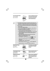
... Jack Sensing, but the panel wire on the lower right hand taskbar to enter Realtek HD Audio Manager. Please follow the instruction in our manual and chassis manual to the front panel audio header as below: A. B. You don't need to function correctly. F. Enter Windows system. If you use AC'97 audio panel...
... Jack Sensing, but the panel wire on the lower right hand taskbar to enter Realtek HD Audio Manager. Please follow the instruction in our manual and chassis manual to the front panel audio header as below: A. B. You don't need to function correctly. F. Enter Windows system. If you use AC'97 audio panel...
User Manual
Page 33
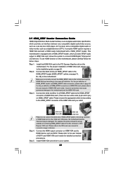
...shows the wrong example of connecting HDMI_SPDIF cable to the installation guide on HDMI VGA card, please refer to the user manual of HDMI_SPDIF cable to the VGA card user manual for detailed connection procedures. Step 5. Install HDMI VGA card driver to the same pin definition. Make sure to correctly ... card, allows the system to HDMI device, such as a digital television (DTV). Connect the white end (B or C) of HDMI_SPDIF cable to the user manual of HDMI VGA card. (There are two white ends (2-pin and 3-pin) on HDMI VGA card to connect HDMI Digital TV/projector/ LCD devices. For...
...shows the wrong example of connecting HDMI_SPDIF cable to the installation guide on HDMI VGA card, please refer to the user manual of HDMI_SPDIF cable to the VGA card user manual for detailed connection procedures. Step 5. Install HDMI VGA card driver to the same pin definition. Make sure to correctly ... card, allows the system to HDMI device, such as a digital television (DTV). Connect the white end (B or C) of HDMI_SPDIF cable to the user manual of HDMI VGA card. (There are two white ends (2-pin and 3-pin) on HDMI VGA card to connect HDMI Digital TV/projector/ LCD devices. For...
User Manual
Page 37
... HDD 1x4-pin conventional power connector (White) connect to use the SATA power cable & data cable, which are from your dealer or HDD user manual. Make sure to power supply Caution 1. The SATA / SATAII HDD, which cannot support Hot Plug function, will cause the HDD damage and data loss...and will be processed. 2. Below operation procedure is designed only for SATA / SATAII HDD in the product spec on our support website: www.asrock.com 4. Even some SATA / SATAII HDDs provide both SATA 15-pin power connector and IDE 1x4-pin conventional power connector interfaces, the IDE 1x4...
... HDD 1x4-pin conventional power connector (White) connect to use the SATA power cable & data cable, which are from your dealer or HDD user manual. Make sure to power supply Caution 1. The SATA / SATAII HDD, which cannot support Hot Plug function, will cause the HDD damage and data loss...and will be processed. 2. Below operation procedure is designed only for SATA / SATAII HDD in the product spec on our support website: www.asrock.com 4. Even some SATA / SATAII HDDs provide both SATA 15-pin power connector and IDE 1x4-pin conventional power connector interfaces, the IDE 1x4...
User Manual
Page 46
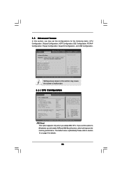
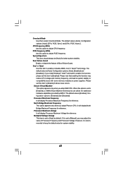
...] [Auto] If AUTO, multiplier and voltage will be left at the rated frequency/voltage. The default value is [Disabled]. If Manual, multiplier and voltage will be set based on page 9 for the following items: CPU Configuration, Chipset Configuration, ACPI Configuration, IDE ...Configuration, Floppy Configuration, SuperIO Configuration, and USB Configuration. 3.3 Advanced Screen In this option to [Enabled], you will enable ASRock AM2 Boost function, which will improve the memory performance. Main BIOS SETUP UTILITY Advanced H/W Monitor Boot Security Exit Advanced Settings...
...] [Auto] If AUTO, multiplier and voltage will be left at the rated frequency/voltage. The default value is [Disabled]. If Manual, multiplier and voltage will be set based on page 9 for the following items: CPU Configuration, Chipset Configuration, ACPI Configuration, IDE ...Configuration, Floppy Configuration, SuperIO Configuration, and USB Configuration. 3.3 Advanced Screen In this option to [Enabled], you will enable ASRock AM2 Boost function, which will improve the memory performance. Main BIOS SETUP UTILITY Advanced H/W Monitor Boot Security Exit Advanced Settings...
User Manual
Page 47
... It will display Processor Maximum Frequency for reference. Overclock Mode Use this item to [Disable] if above issue occurs. The default value is set to [Manual], you install Windows® VistaTM and want to enable this function, please set to [Auto] by AMD-V. Spread Spectrum This item should always be [Auto...
... It will display Processor Maximum Frequency for reference. Overclock Mode Use this item to [Disable] if above issue occurs. The default value is set to [Manual], you install Windows® VistaTM and want to enable this function, please set to [Auto] by AMD-V. Spread Spectrum This item should always be [Auto...
User Manual
Page 48
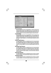
...system stability, it will be hidden. The range of this motherboard. otherwise, it is not recommended to [Manual]; otherwise, it is not recommended to [Manual]; If Manual, multiplier and voltage will be hidden. This item will show when "Multiplier/Voltage Change" is set to adjust... Processor Voltage Memory Clock Flexibility Option [Disabled] [Auto] [200] [100] [Auto] [Enabled] [Auto] [Enabled] x15.0 3000 MHz 1.400 V [Manual] [x9.0 1800 MHz] [1.350 V] [Auto] [Disabled] If AUTO, multiplier and voltage will be hidden. Processor Frequency This option appears only when you ...
...system stability, it will be hidden. The range of this motherboard. otherwise, it is not recommended to [Manual]; otherwise, it is not recommended to [Manual]; If Manual, multiplier and voltage will be hidden. This item will show when "Multiplier/Voltage Change" is set to adjust... Processor Voltage Memory Clock Flexibility Option [Disabled] [Auto] [200] [100] [Auto] [Enabled] [Auto] [Enabled] x15.0 3000 MHz 1.400 V [Manual] [x9.0 1800 MHz] [1.350 V] [Auto] [Disabled] If AUTO, multiplier and voltage will be hidden. Processor Frequency This option appears only when you ...
Quick Installation Guide
Page 5
..., the content of this manual, chapter 1 and 2 contain introduction of this motherboard, please visit our website for purchasing ASRock A780FullDisplayPort motherboard, a reliable motherboard produced under ASRock's consistently stringent quality control. www.asrock.com/support/index.asp 1.1 Package Contents 1 x ASRock A780FullDisplayPort Motherboard (Micro ATX Form Factor: 9.6-in x 9.6-in, 24.4 cm x 24.4 cm) 1 x ASRock A780FullDisplayPort Quick Installation Guide 2 x ASRock A780FullDisplayPort Support CD 1 x Ultra...
..., the content of this manual, chapter 1 and 2 contain introduction of this motherboard, please visit our website for purchasing ASRock A780FullDisplayPort motherboard, a reliable motherboard produced under ASRock's consistently stringent quality control. www.asrock.com/support/index.asp 1.1 Package Contents 1 x ASRock A780FullDisplayPort Motherboard (Micro ATX Form Factor: 9.6-in x 9.6-in, 24.4 cm x 24.4 cm) 1 x ASRock A780FullDisplayPort Quick Installation Guide 2 x ASRock A780FullDisplayPort Support CD 1 x Ultra...
Quick Installation Guide
Page 14
... Down And Lock The Socket Lever 2.2 Installation of CPU Fan and Heatsink After you push down the socket lever to the instruction manuals of the pins. English 14 ASRock A780FullDisplayPort Motherboard Unlock the socket by lifting the lever up to avoid bending of the CPU fan and the heatsink. DO NOT force the...
... Down And Lock The Socket Lever 2.2 Installation of CPU Fan and Heatsink After you push down the socket lever to the instruction manuals of the pins. English 14 ASRock A780FullDisplayPort Motherboard Unlock the socket by lifting the lever up to avoid bending of the CPU fan and the heatsink. DO NOT force the...
Quick Installation Guide
Page 27
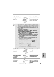
Please follow the instruction in our manual and chassis manual to the ground pin. 27 ASRock A780FullDisplayPort Motherboard English Enter BIOS Setup Utility. F. System Panel Header (9-pin PANEL1) (see p.2, No. 29) This is an interface for the front panel audio cable that ...
Please follow the instruction in our manual and chassis manual to the ground pin. 27 ASRock A780FullDisplayPort Motherboard English Enter BIOS Setup Utility. F. System Panel Header (9-pin PANEL1) (see p.2, No. 29) This is an interface for the front panel audio cable that ...
Quick Installation Guide
Page 30
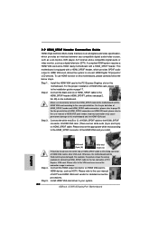
...vendor for connector usage in advance. English white end (2-pin) (B) white end (3-pin) (C) Step 4. Please refer to the user manual of HDMI_SPDIF header and HDMI_SPDIF cable connectors, please refer to page 29. 2.9 HDMI_SPDIF Header Connection Guide HDMI (High-Definition Multi-media Interface...of HDMI VGA card, please refer to the PCI Express Graphics slot on this motherboard. Please refer to your system. 30 ASRock A780FullDisplayPort Motherboard To use HDMI function on this motherboard, please carefully follow the below steps. •Step 1. For the proper ...
...vendor for connector usage in advance. English white end (2-pin) (B) white end (3-pin) (C) Step 4. Please refer to the user manual of HDMI_SPDIF header and HDMI_SPDIF cable connectors, please refer to page 29. 2.9 HDMI_SPDIF Header Connection Guide HDMI (High-Definition Multi-media Interface...of HDMI VGA card, please refer to the PCI Express Graphics slot on this motherboard. Please refer to your system. 30 ASRock A780FullDisplayPort Motherboard To use HDMI function on this motherboard, please carefully follow the below steps. •Step 1. For the proper ...
Quick Installation Guide
Page 38
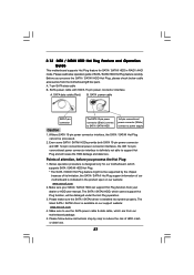
...to scroll through its test routines. When you to enter BIOS Setup utility; The BIOS Setup program is designed to display the menus. 38 ASRock A780FullDisplayPort Motherboard English Software Support CD information This motherboard supports various Microsoft® Windows® operating systems: XP / XP Media Center / XP ...64-bit / VistaTM / VistaTM 64-bit. For the detailed information about BIOS Setup, please refer to the User Manual (PDF file) contained in the Support CD to be user-friendly. If the Main Menu does not appear automatically, locate and double-click...
...to scroll through its test routines. When you to enter BIOS Setup utility; The BIOS Setup program is designed to display the menus. 38 ASRock A780FullDisplayPort Motherboard English Software Support CD information This motherboard supports various Microsoft® Windows® operating systems: XP / XP Media Center / XP ...64-bit / VistaTM / VistaTM 64-bit. For the detailed information about BIOS Setup, please refer to the User Manual (PDF file) contained in the Support CD to be user-friendly. If the Main Menu does not appear automatically, locate and double-click...
