User Manual
Page 6
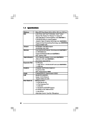
...; Extreme Graphics 2 - Boot Failure Guard (B.F.G.) - 3 x PCI slots - 1 x AGP slot for external graphics (see CAUTION 5) - Supports Wake-On-LAN ASRock I /O - LGA 775 for internal graphics - capacity: 2GB - Supports Hyper-Threading Technology (see CAUTION 8) - 1 x AMR slot - Max. Micro ATX Form..., 24.4 cm x 20.3 cm - Supports Untied Overclocking Technology (see CAUTION 7) - Southbridge: Intel® ICH5 - ASRock U-COP (see CAUTION 3) - Max. Cmedia 9761A 5.1 channel audio CODEC - Speed: 10/100 Ethernet - Audio Jack: Line In / Line Out / Microphone 6
...; Extreme Graphics 2 - Boot Failure Guard (B.F.G.) - 3 x PCI slots - 1 x AGP slot for external graphics (see CAUTION 5) - Supports Wake-On-LAN ASRock I /O - LGA 775 for internal graphics - capacity: 2GB - Supports Hyper-Threading Technology (see CAUTION 8) - 1 x AMR slot - Max. Micro ATX Form..., 24.4 cm x 20.3 cm - Supports Untied Overclocking Technology (see CAUTION 7) - Southbridge: Intel® ICH5 - ASRock U-COP (see CAUTION 3) - Max. Cmedia 9761A 5.1 channel audio CODEC - Speed: 10/100 Ethernet - Audio Jack: Line In / Line Out / Microphone 6

User Manual
Page 7
Front panel audio connector - 2 x USB 2.0 headers (support 4 USB 2.0 ports; 2 of your system. SMBIOS 2.3.1 Support - Chassis Fan Tachometer - We are shared with overclocking, including adjusting the setting in the ...
Front panel audio connector - 2 x USB 2.0 headers (support 4 USB 2.0 ports; 2 of your system. SMBIOS 2.3.1 Support - Chassis Fan Tachometer - We are shared with overclocking, including adjusting the setting in the ...
User Manual
Page 9
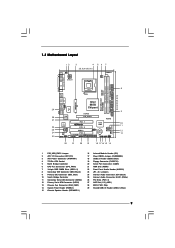
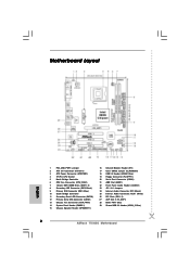
...: RJ-45 USB 2.0 T: USB0 B: USB1 USB 2.0 T: USB2 B: USB3 USB 2.0 1 T: USB4 B: USB5 IDE2 Intel 865G Chipset 775i65G USB4_5 Super I/O ATXPWR1 4Mb BIOS PCI LAN CD1 AUX1 AUDIO CODEC AUDIO1 1 JR1 JL1 AGP8X 1.5V_AGP1 IDE1 RoHS CHA_FAN1 SATA PCI 1 PCI 2 USB2.0 PCI 3 5.1CH FLOPPY1 COM1 AMR1 1 Intel ...Blue) 19 Floppy Connector (FLOPPY1) 20 Serial Port Connector (COM1) 21 AMR Slot (AMR1) 22 Front Panel Audio Header (AUDIO1) 23 JR1 / JL1 Jumpers 24 Internal Audio Connector: CD1 (Black) 25 Internal Audio Connector: AUX1 (White) 26 PCI Slots (PCI1- 3) 27 AGP Slot (1.5V_AGP1) 28 BIOS FWH Chip ...
...: RJ-45 USB 2.0 T: USB0 B: USB1 USB 2.0 T: USB2 B: USB3 USB 2.0 1 T: USB4 B: USB5 IDE2 Intel 865G Chipset 775i65G USB4_5 Super I/O ATXPWR1 4Mb BIOS PCI LAN CD1 AUX1 AUDIO CODEC AUDIO1 1 JR1 JL1 AGP8X 1.5V_AGP1 IDE1 RoHS CHA_FAN1 SATA PCI 1 PCI 2 USB2.0 PCI 3 5.1CH FLOPPY1 COM1 AMR1 1 Intel ...Blue) 19 Floppy Connector (FLOPPY1) 20 Serial Port Connector (COM1) 21 AMR Slot (AMR1) 22 Front Panel Audio Header (AUDIO1) 23 JR1 / JL1 Jumpers 24 Internal Audio Connector: CD1 (Black) 25 Internal Audio Connector: AUX1 (White) 26 PCI Slots (PCI1- 3) 27 AGP Slot (1.5V_AGP1) 28 BIOS FWH Chip ...
User Manual
Page 17
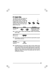
... unplug the power cord from the power supply. 2.7 Jumpers Setup The illustration shows how jumpers are short, both the front panel and the rear panel audio connectors can work.
... unplug the power cord from the power supply. 2.7 Jumpers Setup The illustration shows how jumpers are short, both the front panel and the rear panel audio connectors can work.
User Manual
Page 19
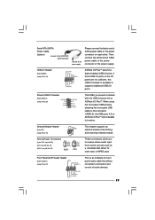
... transmitting and receiving infrared module. Front Panel AC'97 Audio Header (8-pin AUDIO1) (see p.9 No. 18) USB_PWR P-7 P+7 GND DUMMY 1 GND P+6 P-6 USB_PWR ASRock I /O PlusTM will not be able to the power connector on ASRock I /O PlusTM accommodates 6 default USB 2.0 ports. ...Infrared Module Header (5-pin IR1) (see p.9 No. 16) Internal Audio Connectors (4-pin CD1, 4-pin AUX1) (CD1: see p.9 No. 24)...
... transmitting and receiving infrared module. Front Panel AC'97 Audio Header (8-pin AUDIO1) (see p.9 No. 18) USB_PWR P-7 P+7 GND DUMMY 1 GND P+6 P-6 USB_PWR ASRock I /O PlusTM will not be able to the power connector on ASRock I /O PlusTM accommodates 6 default USB 2.0 ports. ...Infrared Module Header (5-pin IR1) (see p.9 No. 16) Internal Audio Connectors (4-pin CD1, 4-pin AUX1) (CD1: see p.9 No. 24)...
User Manual
Page 20
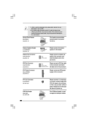
...pin CPU_FAN1) (see p.9 No. 15) 1 SPEAKER DUMMY DUMMY +5V Please connect the chassis speaker to this connector. This COM port header is used for audio power only, please don't connect it to any other power, such as USB. 2. System Panel Header (9-pin PANEL1) (see p.9 No. 20) 20 ...a COM port module. Chassis Fan Connector (3-pin CHA_FAN1) (see p.9 No. 3) Please connect an ATX power supply to power up. HD (Azalia) audio front panel and AC'97 audio front panel have different pin-definition. ATX 12V Connector (4-pin ATX12V1) (see p.9, No. 2) COM Port Header (9-pin COM1) (see p.9 No....
...pin CPU_FAN1) (see p.9 No. 15) 1 SPEAKER DUMMY DUMMY +5V Please connect the chassis speaker to this connector. This COM port header is used for audio power only, please don't connect it to any other power, such as USB. 2. System Panel Header (9-pin PANEL1) (see p.9 No. 20) 20 ...a COM port module. Chassis Fan Connector (3-pin CHA_FAN1) (see p.9 No. 3) Please connect an ATX power supply to power up. HD (Azalia) audio front panel and AC'97 audio front panel have different pin-definition. ATX 12V Connector (4-pin ATX12V1) (see p.9, No. 2) COM Port Header (9-pin COM1) (see p.9 No....
User Manual
Page 26
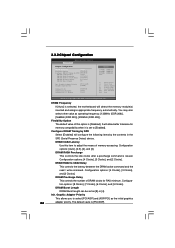
... Timing by the contents in the SPD (Serial Presence Detect) device. Graphic Adapter Priority Graphics Aperture Size [PCI / AGP] [64MB] OnBoard LAN OnBoard AC'97 Audio OnBoard MC'97 Modem [Enabled] [Auto] [Auto] Options 133MHz 166MHz 200MHz Auto (DDR266) (DDR333) (DDR400) +F1 F9 F10 ESC Select Screen Select Item Change Option...
... Timing by the contents in the SPD (Serial Presence Detect) device. Graphic Adapter Priority Graphics Aperture Size [PCI / AGP] [64MB] OnBoard LAN OnBoard AC'97 Audio OnBoard MC'97 Modem [Enabled] [Auto] [Auto] Options 133MHz 166MHz 200MHz Auto (DDR266) (DDR333) (DDR400) +F1 F9 F10 ESC Select Screen Select Item Change Option...
User Manual
Page 27
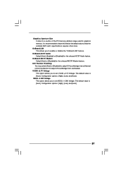
...overheated. OnBoard LAN This allows you to set VDDQ +1.58V Voltage. OnBoard MC'97 Modem Select [Auto] or [Disabled] for the onboard AC'97 Audio feature. VCCM +2.7V Voltage This option allows you to set VCCM +2.7V Voltage. Configuration options: [High], [Low], and [Auto]. VDDQ +1.58V...or [Disabled] to adjust ICH southbridge internal thermal control mechanism to a section of the PCI memory address range used for graphics memory. OnBoard AC'97 Audio Select [Auto], [Enabled] or [Disabled] for the onboard MC'97 Modem feature. Configuration options: [High], [Low], and [Auto]. 27 It ...
...overheated. OnBoard LAN This allows you to set VDDQ +1.58V Voltage. OnBoard MC'97 Modem Select [Auto] or [Disabled] for the onboard AC'97 Audio feature. VCCM +2.7V Voltage This option allows you to set VCCM +2.7V Voltage. Configuration options: [High], [Low], and [Auto]. VDDQ +1.58V...or [Disabled] to adjust ICH southbridge internal thermal control mechanism to a section of the PCI memory address range used for graphics memory. OnBoard AC'97 Audio Select [Auto], [Enabled] or [Disabled] for the onboard MC'97 Modem feature. Configuration options: [High], [Low], and [Auto]. 27 It ...
Quick Installation Guide
Page 2
... Floppy Connector (FLOPPY1) 20 Serial Port Connector (COM1) 21 AMR Slot (AMR1) 22 Front Panel Audio Header (AUDIO1) 23 JR1 / JL1 Jumpers 24 Internal Audio Connector: CD1 (Black) 25 Internal Audio Connector: AUX1 (White) 26 PCI Slots (PCI1- 3) 27 AGP Slot (1.5V_AGP1) 28 BIOS FWH Chip 29 Shared USB 2.0 Header (USB4_5, Blue) 2 ASRock 775i65G Motherboard
... Floppy Connector (FLOPPY1) 20 Serial Port Connector (COM1) 21 AMR Slot (AMR1) 22 Front Panel Audio Header (AUDIO1) 23 JR1 / JL1 Jumpers 24 Internal Audio Connector: CD1 (Black) 25 Internal Audio Connector: AUX1 (White) 26 PCI Slots (PCI1- 3) 27 AGP Slot (1.5V_AGP1) 28 BIOS FWH Chip 29 Shared USB 2.0 Header (USB4_5, Blue) 2 ASRock 775i65G Motherboard
Quick Installation Guide
Page 5
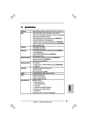
...: 9.6-in x 8.0-in, 24.4 cm x 20.3 cm - capacity: 2GB - Cmedia 9761A 5.1 channel audio CODEC - Supports Untied Overclocking Technology (see CAUTION 7) - ASRock U-COP (see CAUTION 3) - Audio Jack: Line In / Line Out / Microphone English 5 ASRock 775i65G Motherboard 1.2 Specifications Platform CPU Chipset Memory Hybrid Booster Expansion Slot Graphics Audio LAN Rear Panel I /O PlusTM - 1 x PS/2 Mouse Port - 1 x PS/2 Keyboard Port - 1 x VGA...
...: 9.6-in x 8.0-in, 24.4 cm x 20.3 cm - capacity: 2GB - Cmedia 9761A 5.1 channel audio CODEC - Supports Untied Overclocking Technology (see CAUTION 7) - ASRock U-COP (see CAUTION 3) - Audio Jack: Line In / Line Out / Microphone English 5 ASRock 775i65G Motherboard 1.2 Specifications Platform CPU Chipset Memory Hybrid Booster Expansion Slot Graphics Audio LAN Rear Panel I /O PlusTM - 1 x PS/2 Mouse Port - 1 x PS/2 Keyboard Port - 1 x VGA...
Quick Installation Guide
Page 6
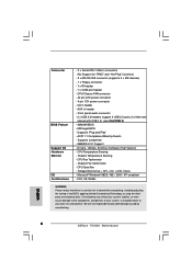
..., applying Untied Overclocking Technology, or using the thirdparty overclocking tools. ACPI 1.1 Compliance Wake Up Events - SMBIOS 2.3.1 Support - CPU Fan Tachometer - CPU Quiet Fan - English 6 ASRock 775i65G Motherboard Front panel audio connector - 2 x USB 2.0 headers (support 4 USB 2.0 ports; 2 of your own risk and expense. CPU Temperature Sensing - Microsoft® Windows® 98SE / ME / 2000 / XP...
..., applying Untied Overclocking Technology, or using the thirdparty overclocking tools. ACPI 1.1 Compliance Wake Up Events - SMBIOS 2.3.1 Support - CPU Fan Tachometer - CPU Quiet Fan - English 6 ASRock 775i65G Motherboard Front panel audio connector - 2 x USB 2.0 headers (support 4 USB 2.0 ports; 2 of your own risk and expense. CPU Temperature Sensing - Microsoft® Windows® 98SE / ME / 2000 / XP...
Quick Installation Guide
Page 13
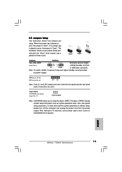
... for 15 seconds, use a jumper cap to default setup, please turn off the computer and unplug the power cord from the power supply. English 13 ASRock 775i65G Motherboard If no jumper cap is placed on pins, the jumper is placed on pins, the jumper is "Short". When the jumper cap is placed... and higher standby current provided by power supply. 2.5 Jumpers Setup The illustration shows how jumpers are short, both the front panel and the rear panel audio connectors can work.
... for 15 seconds, use a jumper cap to default setup, please turn off the computer and unplug the power cord from the power supply. English 13 ASRock 775i65G Motherboard If no jumper cap is placed on pins, the jumper is placed on pins, the jumper is "Short". When the jumper cap is placed... and higher standby current provided by power supply. 2.5 Jumpers Setup The illustration shows how jumpers are short, both the front panel and the rear panel audio connectors can work.
Quick Installation Guide
Page 15
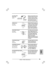
... is shared with the USB 2.0 ports 4,5 on ASRock I/O PlusTM will not be able to function. English 15 ASRock 775i65G Motherboard Shared USB 2.0 Header (9-pin USB4_5) (see p.2 No. 29) This USB4_5 connector is an interface for the front panel audio cable that allows convenient connection and control of audio devices. USB 2.0 Header (9-pin USB67) (see p.2 No...
... is shared with the USB 2.0 ports 4,5 on ASRock I/O PlusTM will not be able to function. English 15 ASRock 775i65G Motherboard Shared USB 2.0 Header (9-pin USB4_5) (see p.2 No. 29) This USB4_5 connector is an interface for the front panel audio cable that allows convenient connection and control of audio devices. USB 2.0 Header (9-pin USB67) (see p.2 No...
Quick Installation Guide
Page 16
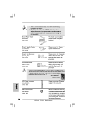
... 3-Pin CPU fan to the CPU fan connector on this motherboard, please connect it to this motherboard. Incorrect connection of the audio front panel and the front panel audio header may cause permanent damage to Pin 1-3. Chassis Speaker Header (4-pin SPEAKER 1) (see p.2 No. 2) ATX 12V plug ... CPU fan cable to this connector and match the black wire to this connector so that it is used for audio power only, please don't connect it to power up. 16 ASRock 775i65G Motherboard English CPU Fan Connector 1 (4-pin CPU_FAN1) 2 3 (see p.2 No. 14) This header accommodates several system ...
... 3-Pin CPU fan to the CPU fan connector on this motherboard, please connect it to this motherboard. Incorrect connection of the audio front panel and the front panel audio header may cause permanent damage to Pin 1-3. Chassis Speaker Header (4-pin SPEAKER 1) (see p.2 No. 2) ATX 12V plug ... CPU fan cable to this connector and match the black wire to this connector so that it is used for audio power only, please don't connect it to power up. 16 ASRock 775i65G Motherboard English CPU Fan Connector 1 (4-pin CPU_FAN1) 2 3 (see p.2 No. 14) This header accommodates several system ...


