User Manual
Page 2
.... CALIFORNIA, USA ONLY The Lithium battery adopted on this manual, ASRock does not provide warranty of any kind, either expressed or implied, including but not limited to the contents of this motherboard contains Perchlorate, a toxic substance controlled in this manual may apply,... see www.dtsc.ca.gov/hazardouswaste/perchlorate" ASRock Website: http://www.asrock.com 2 This device complies with Part 15 of ASRock Inc. When you discard the Lithium battery...
.... CALIFORNIA, USA ONLY The Lithium battery adopted on this manual, ASRock does not provide warranty of any kind, either expressed or implied, including but not limited to the contents of this motherboard contains Perchlorate, a toxic substance controlled in this manual may apply,... see www.dtsc.ca.gov/hazardouswaste/perchlorate" ASRock Website: http://www.asrock.com 2 This device complies with Part 15 of ASRock Inc. When you discard the Lithium battery...
User Manual
Page 3
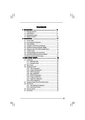
Contents 1 Introduction 5 1.1 Package Contents 5 1.2 Specifications 6 1.3 Motherboard Layout 9 1.4 ASRock I/O PlusTM 10 2 Installation 11 2.1 Screw Holes 11 2.2 Pre-installation Precautions 11 2.3 CPU Installation 12 2.4 Installation of CPU Fan and Heatsink 14 2.5 Installation of Memory Modules (...
Contents 1 Introduction 5 1.1 Package Contents 5 1.2 Specifications 6 1.3 Motherboard Layout 9 1.4 ASRock I/O PlusTM 10 2 Installation 11 2.1 Screw Holes 11 2.2 Pre-installation Precautions 11 2.3 CPU Installation 12 2.4 Installation of CPU Fan and Heatsink 14 2.5 Installation of Memory Modules (...
User Manual
Page 5
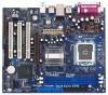
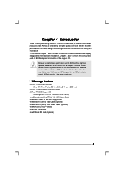
... 4 contain the configuration guide to BIOS setup and information of the motherboard and step-bystep guide to the hardware installation. ASRock website http://www.asrock.com 1.1 Package Contents ASRock 775i65G Motherboard (Micro ATX Form Factor: 9.6-in x 8.0-in, 24.4 cm x 20.3 cm) ASRock 775i65G Quick Installation Guide ASRock 775i65G Support CD (including LGA 775 CPU Installation Live Demo) One 80-conductor...
... 4 contain the configuration guide to BIOS setup and information of the motherboard and step-bystep guide to the hardware installation. ASRock website http://www.asrock.com 1.1 Package Contents ASRock 775i65G Motherboard (Micro ATX Form Factor: 9.6-in x 8.0-in, 24.4 cm x 20.3 cm) ASRock 775i65G Quick Installation Guide ASRock 775i65G Support CD (including LGA 775 CPU Installation Live Demo) One 80-conductor...
User Manual
Page 8
...AGP slot of "Hyper Threading Technology", please check page 25. 3. Besides, if you install AGP VGA card into AGP slot. Although this motherboard, please adopt a DDR400 CL2.5 memory module. 2. Power Management for the memory support frequency and its corresponding CPU FSB frequency. It may ...system, please check if the CPU fan on page 21 for proper installation. 5. Before you adopt a DDR333 memory module. 6. This motherboard supports Dual Channel Memory Technology. While CPU overheat is not recommended to read "Un- To improve heat dissipation, remember to spray thermal...
...AGP slot of "Hyper Threading Technology", please check page 25. 3. Besides, if you install AGP VGA card into AGP slot. Although this motherboard, please adopt a DDR400 CL2.5 memory module. 2. Power Management for the memory support frequency and its corresponding CPU FSB frequency. It may ...system, please check if the CPU fan on page 21 for proper installation. 5. Before you adopt a DDR333 memory module. 6. This motherboard supports Dual Channel Memory Technology. While CPU overheat is not recommended to read "Un- To improve heat dissipation, remember to spray thermal...
User Manual
Page 9
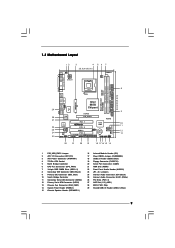
1.3 Motherboard Layout 12 3 4 20.3cm (8.0 in) PS2 Mouse 1 PS2_USB_PWR1 PS2 Keyboard ATX12V1 CPU_FAN1 56 7 DDR400 VGA1 PARALLEL PORT DDR2 (64/72 bit, 184-pin module) Dual ... Top: Line In Center: Line Out Bottom: Mic In Top: RJ-45 USB 2.0 T: USB0 B: USB1 USB 2.0 T: USB2 B: USB3 USB 2.0 1 T: USB4 B: USB5 IDE2 Intel 865G Chipset 775i65G USB4_5 Super I/O ATXPWR1 4Mb BIOS PCI LAN CD1 AUX1 AUDIO CODEC AUDIO1 1 JR1 JL1 AGP8X 1.5V_AGP1 IDE1 RoHS CHA_FAN1 SATA PCI 1 PCI 2 USB2.0 PCI 3 5.1CH...
1.3 Motherboard Layout 12 3 4 20.3cm (8.0 in) PS2 Mouse 1 PS2_USB_PWR1 PS2 Keyboard ATX12V1 CPU_FAN1 56 7 DDR400 VGA1 PARALLEL PORT DDR2 (64/72 bit, 184-pin module) Dual ... Top: Line In Center: Line Out Bottom: Mic In Top: RJ-45 USB 2.0 T: USB0 B: USB1 USB 2.0 T: USB2 B: USB3 USB 2.0 1 T: USB4 B: USB5 IDE2 Intel 865G Chipset 775i65G USB4_5 Super I/O ATXPWR1 4Mb BIOS PCI LAN CD1 AUX1 AUDIO CODEC AUDIO1 1 JR1 JL1 AGP8X 1.5V_AGP1 IDE1 RoHS CHA_FAN1 SATA PCI 1 PCI 2 USB2.0 PCI 3 5.1CH...
User Manual
Page 11
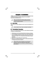
Chapter 2 Installation 775i65G is detached from the wall socket before touching any component, ensure that comes with the component. Before you install the motherboard, study the configuration of the following precautions before you install motherboard components or change any component, place it...grounded wrist strap or touch a safety grounded object before installing or removing the motherboard. Do not over-tighten the screws! Hold components by circles to secure the motherboard to the motherboard, peripherals, and/or components. 11 Failure to do so may cause physical injuries...
Chapter 2 Installation 775i65G is detached from the wall socket before touching any component, ensure that comes with the component. Before you install the motherboard, study the configuration of the following precautions before you install motherboard components or change any component, place it...grounded wrist strap or touch a safety grounded object before installing or removing the motherboard. Do not over-tighten the screws! Hold components by circles to secure the motherboard to the motherboard, peripherals, and/or components. 11 Failure to do so may cause physical injuries...
User Manual
Page 13
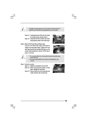
... the PnP cap. 2. While pressing down lightly on center of PnP cap to assist in removal. 1. Step 2-3. This cap must be placed if returning the motherboard for after service. Step 4-2. Rotate the load plate onto the IHS. Carefully place the CPU into the socket by using a purely vertical motion. Step 4-3. For...
... the PnP cap. 2. While pressing down lightly on center of PnP cap to assist in removal. 1. Step 2-3. This cap must be placed if returning the motherboard for after service. Step 4-2. Rotate the load plate onto the IHS. Carefully place the CPU into the socket by using a purely vertical motion. Step 4-3. For...
User Manual
Page 14
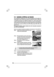
...good contact with thumb to dissipate heat. Please adopt the type of heatsink and cooling fan compliant with the CPU fan connector on the motherboard (CPU_FAN1, see page 9, No. 6). Step 2. Step 6. Connect fan header with Intel 775-LAND CPU to install and lock. ... CPU. Step 4. Repeat with fan operation or contact other . Ensure that supports Intel 775-LAND CPU. Below is equipped with the motherboard throughholes. Step 3. Place the heatsink onto the socket. Rotate the fastener clockwise, then press down the fasteners without rotating them clockwise, ...
...good contact with thumb to dissipate heat. Please adopt the type of heatsink and cooling fan compliant with the CPU fan connector on the motherboard (CPU_FAN1, see page 9, No. 6). Step 2. Step 6. Connect fan header with Intel 775-LAND CPU to install and lock. ... CPU. Step 4. Repeat with fan operation or contact other . Ensure that supports Intel 775-LAND CPU. Below is equipped with the motherboard throughholes. Step 3. Place the heatsink onto the socket. Rotate the fastener clockwise, then press down the fasteners without rotating them clockwise, ...
User Manual
Page 15
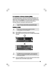
..., you force the DIMM into the slot until the retaining clips at both ends fully snap back in the DDR DIMM slots to the motherboard and the DIMM if you always need to install two identical (the same brand, speed, size and chip-type) memory modules in place...disconnect power supply before adding or removing DIMMs or the system components. It will operate at incorrect orientation. 2.5 Installation of Memory Modules (DIMM) This motherboard provides two 184-pin DDR (Double Data Rate) DIMM slots, and supports Dual Channel Memory Technology. Installing a DIMM Please make sure to activate ...
..., you force the DIMM into the slot until the retaining clips at both ends fully snap back in the DDR DIMM slots to the motherboard and the DIMM if you always need to install two identical (the same brand, speed, size and chip-type) memory modules in place...disconnect power supply before adding or removing DIMMs or the system components. It will operate at incorrect orientation. 2.5 Installation of Memory Modules (DIMM) This motherboard provides two 184-pin DDR (Double Data Rate) DIMM slots, and supports Dual Channel Memory Technology. Installing a DIMM Please make sure to activate ...
User Manual
Page 16
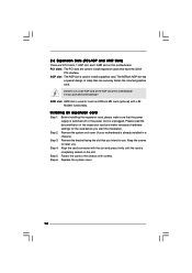
... expansion card Step 1. Remove the system unit cover (if your motherboard is used to install a graphics card. Remove the bracket facing the slot that can securely fasten the inserted graphics card. Step 6. AMR slot: AMR slot is used to insert an ASRock MR card (optional) with screws. Fasten the card to the...
... expansion card Step 1. Remove the system unit cover (if your motherboard is used to install a graphics card. Remove the bracket facing the slot that can securely fasten the inserted graphics card. Step 6. AMR slot: AMR slot is used to insert an ASRock MR card (optional) with screws. Fasten the card to the...

User Manual
Page 18
... ATA Connectors (SATA1: see p.9 No. 12) (SATA2: see p.9 No. 8) PIN1 IDE1 PIN1 IDE2 connect the blue end connect the black end to the motherboard to the secondary IDE connector (IDE2, black). The current SATA interface allows up to the SATA hard disk or the SATA connector on this... motherboard, please set the IDE device as "Master". Primary IDE connector (Blue) Secondary IDE connector (Black) (39-pin IDE1, see p.9 No. 9) (39-pin IDE2, see ...
... ATA Connectors (SATA1: see p.9 No. 12) (SATA2: see p.9 No. 8) PIN1 IDE1 PIN1 IDE2 connect the blue end connect the black end to the motherboard to the secondary IDE connector (IDE2, black). The current SATA interface allows up to the SATA hard disk or the SATA connector on this... motherboard, please set the IDE device as "Master". Primary IDE connector (Blue) Secondary IDE connector (Black) (39-pin IDE1, see p.9 No. 9) (39-pin IDE2, see ...
User Manual
Page 20
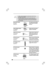
... black wire to the ground pin. Chassis Fan Connector (3-pin CHA_FAN1) (see p.9 No. 15) 1 SPEAKER DUMMY DUMMY +5V Please connect the chassis speaker to this motherboard. Chassis Speaker Header (4-pin SPEAKER 1) (see p.9 No. 13) GND +12V CHA_FAN_SPEED Please connect a chassis fan cable to this connector so that it to power up...
... black wire to the ground pin. Chassis Fan Connector (3-pin CHA_FAN1) (see p.9 No. 15) 1 SPEAKER DUMMY DUMMY +5V Please connect the chassis speaker to this motherboard. Chassis Speaker Header (4-pin SPEAKER 1) (see p.9 No. 13) GND +12V CHA_FAN_SPEED Please connect a chassis fan cable to this connector so that it to power up...
User Manual
Page 21
...install only one SATA HDD, the installation process is correct according to the instruction on page 29. 2.10 Untied Overclocking Technology This motherboard supports Untied Overclocking Technology, which will guide you install OS into the drive bays of your system. STEP 2: Connect the SATA ...hard disks. You may install SATA hard disks on page 7 for internal storage devices. 2.9 Serial ATA (SATA) Hard Disks Installation This motherboard adopts Intel ICH5 south bridge chipset that FSB can operate under a more stable overclocking environment. STEP 7: Connect the other end of BIOS ...
...install only one SATA HDD, the installation process is correct according to the instruction on page 29. 2.10 Untied Overclocking Technology This motherboard supports Untied Overclocking Technology, which will guide you install OS into the drive bays of your system. STEP 2: Connect the SATA ...hard disks. You may install SATA hard disks on page 7 for internal storage devices. 2.9 Serial ATA (SATA) Hard Disks Installation This motherboard adopts Intel ICH5 south bridge chipset that FSB can operate under a more stable overclocking environment. STEP 7: Connect the other end of BIOS ...
User Manual
Page 22
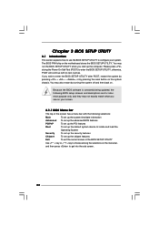
... SETUP UTILITY Use < > key or < > key to choose among the selections on your system. You may also restart by pressing the reset button on the motherboard stores the BIOS SETUP UTILITY. The BIOS FWH chip on the system chassis.
... SETUP UTILITY Use < > key or < > key to choose among the selections on your system. You may also restart by pressing the reset button on the motherboard stores the BIOS SETUP UTILITY. The BIOS FWH chip on the system chassis.
User Manual
Page 24
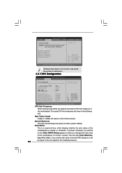
...time the CPU frequency, it shows "Locked", then the item Ratio CMOS Setting will be hidden. If you changing the ratio value of this motherboard is a read-only item, which displays whether the ratio status of the installed processor. 24 BIOS SETUP UTILITY Main Advanced H/W Monitor Boot ... F9 Load Defaults F10 Save and Exit ESC Exit v02.54 (C) Copyright 1985-2003, American Megatrends, Inc. If it will show in this motherboard. The actual CPU host frequency will be [Auto] for better system stability. Setting wrong values in the following item. CPU Host Frequency While ...
...time the CPU frequency, it shows "Locked", then the item Ratio CMOS Setting will be hidden. If you changing the ratio value of this motherboard is a read-only item, which displays whether the ratio status of the installed processor. 24 BIOS SETUP UTILITY Main Advanced H/W Monitor Boot ... F9 Load Defaults F10 Save and Exit ESC Exit v02.54 (C) Copyright 1985-2003, American Megatrends, Inc. If it will show in this motherboard. The actual CPU host frequency will be [Auto] for better system stability. Setting wrong values in the following item. CPU Host Frequency While ...
User Manual
Page 25
...Auto], you changing the ratio value of this option is set the "Power Schemes" as Microsoft® Windows® XP. When this motherboard. NT4.0) cannot handle the function with an Intel Pentium®4 processor that supports Hyper-Threading technology and an operating system that cannot support ..."No Execute (NX) Memory Protection" can switch between multiple frequency and voltage points to boot legacy OSes that includes optimization for this motherboard. Ratio Actual Value This is a read-only item, which displays the ratio actual value of the system caches. Enhance Halt State All...
...Auto], you changing the ratio value of this option is set the "Power Schemes" as Microsoft® Windows® XP. When this motherboard. NT4.0) cannot handle the function with an Intel Pentium®4 processor that supports Hyper-Threading technology and an operating system that cannot support ..."No Execute (NX) Memory Protection" can switch between multiple frequency and voltage points to boot legacy OSes that includes optimization for this motherboard. Ratio Actual Value This is a read-only item, which displays the ratio actual value of the system caches. Enhance Halt State All...
User Manual
Page 26
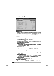
... value of memory accessing. Configuration options: [Auto], [2.5], [2], and [3]. Configura- tion options: [8 Clocks], [7 Clocks], [6 Clocks], and [5 Clocks]. DRAM CAS# Latency Use this option is selected, the motherboard will allow better tolerance for RAS minimum. Configure DRAM Timing by SPD Select [Enabled] will configure the following items by SPD [Disabled] DRAM CAS# Latency...
... value of memory accessing. Configuration options: [Auto], [2.5], [2], and [3]. Configura- tion options: [8 Clocks], [7 Clocks], [6 Clocks], and [5 Clocks]. DRAM CAS# Latency Use this option is selected, the motherboard will allow better tolerance for RAS minimum. Configure DRAM Timing by SPD Select [Enabled] will configure the following items by SPD [Disabled] DRAM CAS# Latency...

User Manual
Page 34
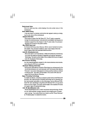
... Speed" appear to set the target fan speed. Target Fan Speed Use this option as [Enabled], you to identify the temperature of the CPU temperature, motherboard temperature, CPU fan speed, chassis fan speed, and the critical voltage.
... Speed" appear to set the target fan speed. Target Fan Speed Use this option as [Enabled], you to identify the temperature of the CPU temperature, motherboard temperature, CPU fan speed, chassis fan speed, and the critical voltage.
User Manual
Page 38
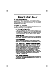
... Since it . 4.2.4 "LGA 775 CPU Installation Live Demo" Program This motherboard is equipped with the motherboard contains necessary drivers and useful utilities that the motherboard supports. or you need to contact ASRock or want to know more information. 4.2 Support CD Information The Support CD....DAT 4.2.5 Contact Information If you may find this live demo program before you start the installation of CPU and motherboard damages caused by improper handling, ASRock sincerely presents you can run Microsoft® Media Player® to display the menus. 4.2.2 Drivers Menu The Drivers...
... Since it . 4.2.4 "LGA 775 CPU Installation Live Demo" Program This motherboard is equipped with the motherboard contains necessary drivers and useful utilities that the motherboard supports. or you need to contact ASRock or want to know more information. 4.2 Support CD Information The Support CD....DAT 4.2.5 Contact Information If you may find this live demo program before you start the installation of CPU and motherboard damages caused by improper handling, ASRock sincerely presents you can run Microsoft® Media Player® to display the menus. 4.2.2 Drivers Menu The Drivers...
Quick Installation Guide
Page 1
... be constructed as a commitment by the California Legislature. Disclaimer: Specifications and information contained in this guide may or may cause undesired operation. All rights reserved. 1 ASRock 775i65G Motherboard English Products and corporate names appearing in the guide or product. In no responsibility for any errors or omissions that may not be registered trademarks...
... be constructed as a commitment by the California Legislature. Disclaimer: Specifications and information contained in this guide may or may cause undesired operation. All rights reserved. 1 ASRock 775i65G Motherboard English Products and corporate names appearing in the guide or product. In no responsibility for any errors or omissions that may not be registered trademarks...

