User Manual
Page 3
... Serial ATA (SATA) Hard Disks Installation 21 2.10 Untied Overclocking Technology 21 3 BIOS SETUP UTILITY 22 3.1 Introduction 22 3.1.1 BIOS Menu Bar 22 3.1.2 Navigation Keys 23 3.2 Main Screen 23 3.3 Advanced Screen 23 3.3.1 CPU Configuration 24 3.3.2 Chipset Configuration 26 3.3.3 ACPI Configuration 28 3.3.4 IDE Configuration 29 3.3.5 PCIPnP Configuration 31 3.3.6 Floppy Configuration 32 3.3.7 Super IO Configuration 32 3.3.8 USB Configuration 33 3.4 Hardware Health Event Monitoring Screen 34 3.5 Boot Screen 35 3.5.1 Boot Settings Configuration 35 3.5.2 Boot Device Priority...
... Serial ATA (SATA) Hard Disks Installation 21 2.10 Untied Overclocking Technology 21 3 BIOS SETUP UTILITY 22 3.1 Introduction 22 3.1.1 BIOS Menu Bar 22 3.1.2 Navigation Keys 23 3.2 Main Screen 23 3.3 Advanced Screen 23 3.3.1 CPU Configuration 24 3.3.2 Chipset Configuration 26 3.3.3 ACPI Configuration 28 3.3.4 IDE Configuration 29 3.3.5 PCIPnP Configuration 31 3.3.6 Floppy Configuration 32 3.3.7 Super IO Configuration 32 3.3.8 USB Configuration 33 3.4 Hardware Health Event Monitoring Screen 34 3.5 Boot Screen 35 3.5.1 Boot Settings Configuration 35 3.5.2 Boot Device Priority...
User Manual
Page 5
... design conforming to ASRock's commitment to BIOS setup and information of the motherboard and step-bystep guide to change without further notice. Chapter 1 Introduction Thank you for a 3.5-in Floppy Drive One Serial ATA (SATA) Data Cable (Optional) One Serial ATA (SATA) HDD Power Cable (Optional) One ASRock I/O PlusTM Shield One COM Port Bracket One ASRock MR Card (Optional) 5 Chapter 3 and 4 contain the configuration guide to quality and endurance. In this manual occur, the updated version will be available...
... design conforming to ASRock's commitment to BIOS setup and information of the motherboard and step-bystep guide to change without further notice. Chapter 1 Introduction Thank you for a 3.5-in Floppy Drive One Serial ATA (SATA) Data Cable (Optional) One Serial ATA (SATA) HDD Power Cable (Optional) One ASRock I/O PlusTM Shield One COM Port Bracket One ASRock MR Card (Optional) 5 Chapter 3 and 4 contain the configuration guide to quality and endurance. In this manual occur, the updated version will be available...
User Manual
Page 8
... Overclocking Technology. About the setting of memory modules on this motherboard offers stepless control, it will automatically shutdown. Although this motherboard, please adopt a DDR400 CL2.5 memory module. 2. It may cause the instability of this motherboard, it is not recommended to perform over-clocking. This motherboard supports Dual Channel Memory Technology. Before you implement Dual Channel Memory Technology, make sure to spray thermal grease between the CPU and the heatsink when you install AGP VGA card...
... Overclocking Technology. About the setting of memory modules on this motherboard offers stepless control, it will automatically shutdown. Although this motherboard, please adopt a DDR400 CL2.5 memory module. 2. It may cause the instability of this motherboard, it is not recommended to perform over-clocking. This motherboard supports Dual Channel Memory Technology. Before you implement Dual Channel Memory Technology, make sure to spray thermal grease between the CPU and the heatsink when you install AGP VGA card...
User Manual
Page 9
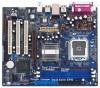
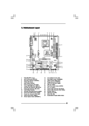
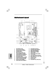
...) 3 ATX Power Connector (ATXPWR1) 4 775-Pin CPU Socket 5 North Bridge Controller 6 CPU Fan Connector (CPU_FAN1) 7 184-pin DDR DIMM Slots (DDR1- 2) 8 Secondary IDE Connector (IDE2, Black) 9 Primary IDE Connector (IDE1, Blue) 10 South Bridge Controller 11 Secondary Serial ATA Connector (SATA2) 12 Primary Serial ATA Connector (SATA1) 13 Chassis Fan Connector (CHA_FAN1) 14 System Panel Header (PANEL1) 15 Chassis Speaker Header (SPEAKER 1) 16 Infrared Module Header (IR1) 17 Clear CMOS Jumper (CLRCMOS0) 18 USB 2.0 Header (USB67, Blue) 19 Floppy Connector (FLOPPY1) 20 Serial Port...
...) 3 ATX Power Connector (ATXPWR1) 4 775-Pin CPU Socket 5 North Bridge Controller 6 CPU Fan Connector (CPU_FAN1) 7 184-pin DDR DIMM Slots (DDR1- 2) 8 Secondary IDE Connector (IDE2, Black) 9 Primary IDE Connector (IDE1, Blue) 10 South Bridge Controller 11 Secondary Serial ATA Connector (SATA2) 12 Primary Serial ATA Connector (SATA1) 13 Chassis Fan Connector (CHA_FAN1) 14 System Panel Header (PANEL1) 15 Chassis Speaker Header (SPEAKER 1) 16 Infrared Module Header (IR1) 17 Clear CMOS Jumper (CLRCMOS0) 18 USB 2.0 Header (USB67, Blue) 19 Floppy Connector (FLOPPY1) 20 Serial Port...
User Manual
Page 19
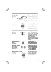
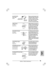
... to the power connector of the power supply. O U T- R MIC-POWER MIC This is available to support 2 additional USB 2.0 ports. Serial ATA (SATA) Power Cable (Optional) connect to the SATA HDD power connector connect to the power supply Please connect the black end of SATA power cable to the power connector on ASRock I /O PlusTM accommodates 6 default USB 2.0 ports. USB 2.0 Header (9-pin USB67) (see p.9 No. 29) 1 USB_PWR P-5 P+5 GND USB_PWR P-4 P+4 GND DUMMY This USB4_5 connector is shared with the USB 2.0 ports 4,5 on each drive. Front Panel AC'97 Audio Header (8-pin AUDIO1...
... to the power connector of the power supply. O U T- R MIC-POWER MIC This is available to support 2 additional USB 2.0 ports. Serial ATA (SATA) Power Cable (Optional) connect to the SATA HDD power connector connect to the power supply Please connect the black end of SATA power cable to the power connector on ASRock I /O PlusTM accommodates 6 default USB 2.0 ports. USB 2.0 Header (9-pin USB67) (see p.9 No. 29) 1 USB_PWR P-5 P+5 GND USB_PWR P-4 P+4 GND DUMMY This USB4_5 connector is shared with the USB 2.0 ports 4,5 on each drive. Front Panel AC'97 Audio Header (8-pin AUDIO1...
User Manual
Page 21
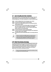
... configuration details, please refer to the instruction on page 29. 2.10 Untied Overclocking Technology This motherboard supports Untied Overclocking Technology, which will guide you the actual CPU host frequency in the following steps. Please refer to [Auto], which means during overclocking, but AGP / PCI bus is in BIOS setup is untied during overclocking, FSB enjoys better margin due to the SATA hard disk. You may install SATA hard disks on page 7 for internal storage devices. You may set "CPU Host Frequency" option...
... configuration details, please refer to the instruction on page 29. 2.10 Untied Overclocking Technology This motherboard supports Untied Overclocking Technology, which will guide you the actual CPU host frequency in the following steps. Please refer to [Auto], which means during overclocking, but AGP / PCI bus is in BIOS setup is untied during overclocking, FSB enjoys better margin due to the SATA hard disk. You may install SATA hard disks on page 7 for internal storage devices. You may set "CPU Host Frequency" option...
User Manual
Page 22
... default system device to locate and load the Operating System Security To set up the security features Chipset To set up the computer. If you wish to get into the sub screen. 22 Chapter 3 BIOS SETUP UTILITY 3.1 Introduction This section explains how to use the BIOS SETUP UTILITY to choose among the selections on the system chassis. You may also restart by pressing the reset button on the menu...
... default system device to locate and load the Operating System Security To set up the security features Chipset To set up the computer. If you wish to get into the sub screen. 22 Chapter 3 BIOS SETUP UTILITY 3.1 Introduction This section explains how to use the BIOS SETUP UTILITY to choose among the selections on the system chassis. You may also restart by pressing the reset button on the menu...
User Manual
Page 24
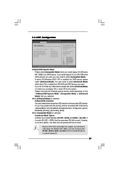
... motherboard. CPU Thermal Throttling No-Excute Memory Protection Hyper Threading Technology Intel (R) SpeedStep(tm) tech. [Disabled] [Disabled] [Enabled] [Enabled] [Disabled] [Enabled] [Auto] Select how to Sub Screen F1 General Help F9 Load Defaults F10 Save and Exit ESC Exit v02.54 (C) Copyright 1985-2003, American Megatrends, Inc. Boot Failure Guard Enable or disable the feature of the installed processor. 24 If it will be [Auto] for better system stability. CPU Host Frequency While entering setup, BIOS auto...
... motherboard. CPU Thermal Throttling No-Excute Memory Protection Hyper Threading Technology Intel (R) SpeedStep(tm) tech. [Disabled] [Disabled] [Enabled] [Enabled] [Disabled] [Enabled] [Auto] Select how to Sub Screen F1 General Help F9 Load Defaults F10 Save and Exit ESC Exit v02.54 (C) Copyright 1985-2003, American Megatrends, Inc. Boot Failure Guard Enable or disable the feature of the installed processor. 24 If it will be [Auto] for better system stability. CPU Host Frequency While entering setup, BIOS auto...
User Manual
Page 25
... Execute (NX) Memory Protection" can switch between multiple frequency and voltage points to [Enabled] if using Microsoft® Windows® XP, or Linux kernel version 2.4.18 or higher. This option will find this option is Intel's new power saving technology. Enhance Halt State All processors support the Halt State (C1). Hyper Threading Technology To enable this motherboard. Intel (R) SpeedStep(tm) tech. If you select [Auto], you changing the ratio...
... Execute (NX) Memory Protection" can switch between multiple frequency and voltage points to [Enabled] if using Microsoft® Windows® XP, or Linux kernel version 2.4.18 or higher. This option will find this option is Intel's new power saving technology. Enhance Halt State All processors support the Halt State (C1). Hyper Threading Technology To enable this motherboard. Intel (R) SpeedStep(tm) tech. If you select [Auto], you changing the ratio...
User Manual
Page 29
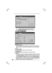
... IDE + SATA] or [SATA + Sec IDE] when the installed SATA device is used. +F1 F9 F10 ESC Select Screen Select Item Change Option General Help Load Defaults Save and Exit Exit v02.54 (C) Copyright 1985-2003, American Megatrends, Inc. Set [Enhanced Mode] when Native OS (Win 2000 / XP) is used with legacy OS. 29 3.3.4 IDE Configuration BIOS SETUP UTILITY Advanced IDE Configuration OnBoard IDE Operate Mode OnBoard IDE Controller Primary IDE Master Primary IDE Slave Secondary IDE Master Secondary IDE Slave SATA1 SATA2 [Enhanced Mode] [Both] [Hard Disk...
... IDE + SATA] or [SATA + Sec IDE] when the installed SATA device is used. +F1 F9 F10 ESC Select Screen Select Item Change Option General Help Load Defaults Save and Exit Exit v02.54 (C) Copyright 1985-2003, American Megatrends, Inc. Set [Enhanced Mode] when Native OS (Win 2000 / XP) is used with legacy OS. 29 3.3.4 IDE Configuration BIOS SETUP UTILITY Advanced IDE Configuration OnBoard IDE Operate Mode OnBoard IDE Controller Primary IDE Master Primary IDE Slave Secondary IDE Master Secondary IDE Slave SATA1 SATA2 [Enhanced Mode] [Both] [Hard Disk...
User Manual
Page 31
... the hard disk timing. Use this item to enable 32-bit access to enhance hard disk performance by reading or writing more data during each transfer. PCI Latency Timer The default value is recommended to enable or disable the S.M.A.R.T. (Self-Monitoring, Analysis, and Reporting Technology) feature. S.M.A.R.T. It is 32. Configuration options: [Disabled], [Auto], [Enabled]. 32-Bit Data Transfer Use this item to keep the default value unless the installed PCI expansion cards' specifications require other settings. DMA Mode...
... the hard disk timing. Use this item to enable 32-bit access to enhance hard disk performance by reading or writing more data during each transfer. PCI Latency Timer The default value is recommended to enable or disable the S.M.A.R.T. (Self-Monitoring, Analysis, and Reporting Technology) feature. S.M.A.R.T. It is 32. Configuration options: [Disabled], [Auto], [Enabled]. 32-Bit Data Transfer Use this item to keep the default value unless the installed PCI expansion cards' specifications require other settings. DMA Mode...
User Manual
Page 32
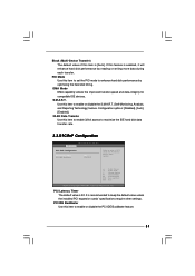
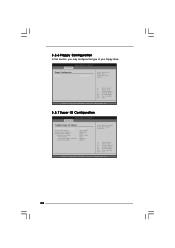
... floppy drive connected to the system. +F1 F9 F10 ESC Select Screen Select Item Change Option General Help Load Defaults Save and Exit Exit v02.54 (C) Copyright 1985-2003, American Megatrends, Inc. 3.3.7 Super IO Configuration BIOS SETUP UTILITY Advanced Configure Super IO Chipset OnBoard Floppy Controller Serial Port Address Infrared Port Address Parallel Port Address Parallel Port Mode EPP Version ECP Mode DMA Channel Parallel Port IRQ [Enabled] [3F8 / IRQ4] [Disabled] [378] [ECP + EPP] [1.9] [DMA3] [IRQ7] Allow BIOS to Enable or Disable Floppy Controller...
... floppy drive connected to the system. +F1 F9 F10 ESC Select Screen Select Item Change Option General Help Load Defaults Save and Exit Exit v02.54 (C) Copyright 1985-2003, American Megatrends, Inc. 3.3.7 Super IO Configuration BIOS SETUP UTILITY Advanced Configure Super IO Chipset OnBoard Floppy Controller Serial Port Address Infrared Port Address Parallel Port Address Parallel Port Mode EPP Version ECP Mode DMA Channel Parallel Port IRQ [Enabled] [3F8 / IRQ4] [Disabled] [378] [ECP + EPP] [1.9] [DMA3] [IRQ7] Allow BIOS to Enable or Disable Floppy Controller...
User Manual
Page 33
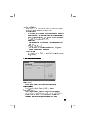
... USB Configuration BIOS SETUP UTILITY Advanced USB Configuration USB Controller USB 2.0 Support Legacy USB Support [Enabled] [Enabled] [Disabled] To enable or disable the onboard USB controllers. +F1 F9 F10 ESC Select Screen Select Item Change Option General Help Load Defaults Save and Exit Exit v02.54 (C) Copyright 1985-2003, American Megatrends, Inc. Configuration options: [Disabled], [378], and [278]. Configuration options: [1.9] and [1.7]. ECP Mode DMA Channel Use this item to [ECP+EPP], it . Parallel Port IRQ Use this item to enable or disable the USB 2.0 support. USB...
... USB Configuration BIOS SETUP UTILITY Advanced USB Configuration USB Controller USB 2.0 Support Legacy USB Support [Enabled] [Enabled] [Disabled] To enable or disable the onboard USB controllers. +F1 F9 F10 ESC Select Screen Select Item Change Option General Help Load Defaults Save and Exit Exit v02.54 (C) Copyright 1985-2003, American Megatrends, Inc. Configuration options: [Disabled], [378], and [278]. Configuration options: [1.9] and [1.7]. ECP Mode DMA Channel Use this item to [ECP+EPP], it . Parallel Port IRQ Use this item to enable or disable the USB 2.0 support. USB...
User Manual
Page 36
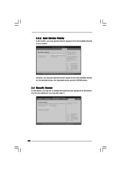
... removable drives, and the CD/DVD drives. 3.6 Security Screen In this section, you may specify the boot sequence from the available devices. BIOS SETUP UTILITY Main Advanced H/W Monitor Boot Security Exit Security Settings Supervisor Password : Not Installed User Password : Not Installed Change Supervisor Password Change User Password Clear User Password Install or Change the password. A device enclosed in parenthesis has been disabled in your system. BIOS SETUP UTILITY Boot Boot Device Priority 1st Boot Device 2nd Boot Device 3rd Boot Device [1st FLOPPY DRIVE] [HDD...
... removable drives, and the CD/DVD drives. 3.6 Security Screen In this section, you may specify the boot sequence from the available devices. BIOS SETUP UTILITY Main Advanced H/W Monitor Boot Security Exit Security Settings Supervisor Password : Not Installed User Password : Not Installed Change Supervisor Password Change User Password Clear User Password Install or Change the password. A device enclosed in parenthesis has been disabled in your system. BIOS SETUP UTILITY Boot Boot Device Priority 1st Boot Device 2nd Boot Device 3rd Boot Device [1st FLOPPY DRIVE] [HDD...
User Manual
Page 38
...-ROM drive. You may check this chapter for further information. 38 Please install the necessary drivers to visit ASRock's website at http://www.asrock.com; Because motherboard settings and hardware options vary, use the setup procedures in your OS documentation for more about ASRock, welcome to activate the devices. 4.2.3 Utilities Menu The Utilities Menu shows the applications software that enhance the motherboard features. 4.2.1 Running The Support CD To begin using the support...
...-ROM drive. You may check this chapter for further information. 38 Please install the necessary drivers to visit ASRock's website at http://www.asrock.com; Because motherboard settings and hardware options vary, use the setup procedures in your OS documentation for more about ASRock, welcome to activate the devices. 4.2.3 Utilities Menu The Utilities Menu shows the applications software that enhance the motherboard features. 4.2.1 Running The Support CD To begin using the support...
Quick Installation Guide
Page 2
...) 3 ATX Power Connector (ATXPWR1) 4 775-Pin CPU Socket 5 North Bridge Controller 6 CPU Fan Connector (CPU_FAN1) 7 184-pin DDR DIMM Slots (DDR1- 2) 8 Secondary IDE Connector (IDE2, Black) 9 Primary IDE Connector (IDE1, Blue) 10 South Bridge Controller 11 Secondary Serial ATA Connector (SATA2) 12 Primary Serial ATA Connector (SATA1) 13 Chassis Fan Connector (CHA_FAN1) 14 System Panel Header (PANEL1) 15 Chassis Speaker Header (SPEAKER 1) 16 Infrared Module Header (IR1) 17 Clear CMOS Jumper (CLRCMOS0) 18 USB 2.0 Header (USB67, Blue) 19 Floppy Connector (FLOPPY1) 20 Serial Port...
...) 3 ATX Power Connector (ATXPWR1) 4 775-Pin CPU Socket 5 North Bridge Controller 6 CPU Fan Connector (CPU_FAN1) 7 184-pin DDR DIMM Slots (DDR1- 2) 8 Secondary IDE Connector (IDE2, Black) 9 Primary IDE Connector (IDE1, Blue) 10 South Bridge Controller 11 Secondary Serial ATA Connector (SATA2) 12 Primary Serial ATA Connector (SATA1) 13 Chassis Fan Connector (CHA_FAN1) 14 System Panel Header (PANEL1) 15 Chassis Speaker Header (SPEAKER 1) 16 Infrared Module Header (IR1) 17 Clear CMOS Jumper (CLRCMOS0) 18 USB 2.0 Header (USB67, Blue) 19 Floppy Connector (FLOPPY1) 20 Serial Port...
Quick Installation Guide
Page 7
... supported only when you install the PC system. 8. This motherboard supports Dual Channel Memory Technology. CPU FSB Frequency Memory Support Frequency 800 DDR266, DDR320*, DDR400 533 DDR266, DDR333 * When you use a 3.3V AGP card on this motherboard! Power Management for the memory support frequency and its corresponding CPU FSB frequency. CAUTION! 1. Please check the table below for USB 2.0 works fine under Microsoft® Windows® 98/ ME. Do NOT use an FSB800-CPU on the AGP slot of "User Manual...
... supported only when you install the PC system. 8. This motherboard supports Dual Channel Memory Technology. CPU FSB Frequency Memory Support Frequency 800 DDR266, DDR320*, DDR400 533 DDR266, DDR333 * When you use a 3.3V AGP card on this motherboard! Power Management for the memory support frequency and its corresponding CPU FSB frequency. CAUTION! 1. Please check the table below for USB 2.0 works fine under Microsoft® Windows® 98/ ME. Do NOT use an FSB800-CPU on the AGP slot of "User Manual...
Quick Installation Guide
Page 15
... USB ports 4,5 on ASRock I/O PlusTM will not be able to -use USB 2.0 ports on the drive. Internal Audio Connectors (4-pin CD1, 4-pin AUX1) (CD1: see p.2 No. 24) (AUX1: see p.2 No. 16) This header supports an optional wireless transmitting and receiving infrared module. Then connect the white end of SATA power cable to the power connector on the rear panel. Serial ATA (SATA) Power Cable (Optional) connect to the SATA HDD power connector connect to the power supply Please connect the black end of SATA power cable to the power connector of...
... USB ports 4,5 on ASRock I/O PlusTM will not be able to -use USB 2.0 ports on the drive. Internal Audio Connectors (4-pin CD1, 4-pin AUX1) (CD1: see p.2 No. 24) (AUX1: see p.2 No. 16) This header supports an optional wireless transmitting and receiving infrared module. Then connect the white end of SATA power cable to the power connector on the rear panel. Serial ATA (SATA) Power Cable (Optional) connect to the SATA HDD power connector connect to the power supply Please connect the black end of SATA power cable to the power connector of...
Quick Installation Guide
Page 17
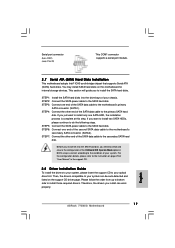
... support CD. 2.8 Driver Installation Guide To install the drivers to your system, please insert the support CD to the instruction on page 29 of your optical drive first. For the configuration details, please refer to your system. STEP 1: Install the SATA hard disks into the SATA hard disk, you just want to install two SATA HDDs, please continue to the condition of "User Manual" in BIOS setup is complete at this motherboard for internal storage devices. STEP 5: Connect the SATA power cable...
... support CD. 2.8 Driver Installation Guide To install the drivers to your system, please insert the support CD to the instruction on page 29 of your optical drive first. For the configuration details, please refer to your system. STEP 1: Install the SATA hard disks into the SATA hard disk, you just want to install two SATA HDDs, please continue to the condition of "User Manual" in BIOS setup is complete at this motherboard for internal storage devices. STEP 5: Connect the SATA power cable...
Quick Installation Guide
Page 18
... display the menus. 18 ASRock 775i65G Motherboard English BIOS Information The Flash Memory on the system chassis. If you wish to the User Manual (PDF file) contained in the following item. For the detailed information about BIOS Setup, please refer to enter BIOS Setup after POST, please restart the system by pressing + + , or pressing the reset button on the motherboard stores BIOS Setup Utility. You may set "CPU Host Frequency" option of BIOS setup to fixed AGP / PCI bus. 2.9 Untied Overclocking Technology This motherboard supports Untied Overclocking Technology...
... display the menus. 18 ASRock 775i65G Motherboard English BIOS Information The Flash Memory on the system chassis. If you wish to the User Manual (PDF file) contained in the following item. For the detailed information about BIOS Setup, please refer to enter BIOS Setup after POST, please restart the system by pressing + + , or pressing the reset button on the motherboard stores BIOS Setup Utility. You may set "CPU Host Frequency" option of BIOS setup to fixed AGP / PCI bus. 2.9 Untied Overclocking Technology This motherboard supports Untied Overclocking Technology...


