
User Manual
Page 3
Definition TV) / TV Support Function 23 2.10.1 HDTV (High-Definition TV) Support Function .... 24 2.10.2 TV Support Function 26 2.11 Untied Overclocking Technology 27 2.12 Serial ATA (...XP 64-bit / VistaTM Installation 28 3 BIOS SETUP UTILITY 29 3.1 Introduction 29 3.1.1 BIOS Menu Bar 29 3.1.2 Navigation Keys 30 3.2 Main Screen 30 3.3 Advanced Screen 31 3.3.1 CPU Configuration 31 3.3.2 Chipset Configuration 33 3.3.3 ACPI Configuration 35 3.3.4 IDE Configuration 36 3.3.5 PCIPnP Configuration 38 3.3.6 Floppy Configuration 39 3 Contents 1 Introduction 5 1.1 Package Contents 5 1.2 ...
Definition TV) / TV Support Function 23 2.10.1 HDTV (High-Definition TV) Support Function .... 24 2.10.2 TV Support Function 26 2.11 Untied Overclocking Technology 27 2.12 Serial ATA (...XP 64-bit / VistaTM Installation 28 3 BIOS SETUP UTILITY 29 3.1 Introduction 29 3.1.1 BIOS Menu Bar 29 3.1.2 Navigation Keys 30 3.2 Main Screen 30 3.3 Advanced Screen 31 3.3.1 CPU Configuration 31 3.3.2 Chipset Configuration 33 3.3.3 ACPI Configuration 35 3.3.4 IDE Configuration 36 3.3.5 PCIPnP Configuration 38 3.3.6 Floppy Configuration 39 3 Contents 1 Introduction 5 1.1 Package Contents 5 1.2 ...

User Manual
Page 4
3.3.7 Super IO Configuration 39 3.3.8 USB Configuration 41 3.4 Hardware Health Event Monitoring Screen 41 3.5 Boot Screen 42 3.5.1 Boot Settings Configuration 42 3.6 Security Screen 43 3.7 Exit Screen 44 4 Software Support 45 4.1 Install Operating System 45 4.2 Support CD Information 45 4.2.1 Running Support CD 45 4.2.2 Drivers Menu 45 4.2.3 Utilities Menu 45 4.2.4 "LGA 775 CPU Installation Live Demo" Program .. 45 4.2.5 Contact Information 45 4
3.3.7 Super IO Configuration 39 3.3.8 USB Configuration 41 3.4 Hardware Health Event Monitoring Screen 41 3.5 Boot Screen 42 3.5.1 Boot Settings Configuration 42 3.6 Security Screen 43 3.7 Exit Screen 44 4 Software Support 45 4.1 Install Operating System 45 4.2 Support CD Information 45 4.2.1 Running Support CD 45 4.2.2 Drivers Menu 45 4.2.3 Utilities Menu 45 4.2.4 "LGA 775 CPU Installation Live Demo" Program .. 45 4.2.5 Contact Information 45 4

User Manual
Page 5
... modifications of this manual, chapter 1 and 2 contain introduction of the Support CD. ASRock website http://www.asrock.com 1.1 Package Contents ASRock 775Twins-HDTV Motherboard (Micro ATX Form Factor: 9.6-in x 9.6-in, 24.4 cm x 24.4 cm) ASRock 775Twins-HDTV Quick Installation Guide ASRock 775Twins-HDTV Support CD (including LGA 775 CPU Installation Live Demo) One 80-conductor Ultra ATA 66/100/133 IDE Ribbon...
... modifications of this manual, chapter 1 and 2 contain introduction of the Support CD. ASRock website http://www.asrock.com 1.1 Package Contents ASRock 775Twins-HDTV Motherboard (Micro ATX Form Factor: 9.6-in x 9.6-in, 24.4 cm x 24.4 cm) ASRock 775Twins-HDTV Quick Installation Guide ASRock 775Twins-HDTV Support CD (including LGA 775 CPU Installation Live Demo) One 80-conductor Ultra ATA 66/100/133 IDE Ribbon...

User Manual
Page 6
... x Serial Port: COM1 - 1 x Parallel Port (ECP/EPP Support) - 4 x Ready-to-Use USB 2.0 Ports 6 Max. Supports EM64T CPU - Supports Untied Overclocking Technology (see CAUTION 3) - CPU Frequency Stepless Control (see CAUTION 2) - DirectX 9.0 VGA - shared memory 128MB - Southbridge: ULi® 1573 - 2 x DDRII DIMM slots - ... channel audio CODEC with High Definition audio - Speed: 10/100Mb Ethernet - Supports Hyper-Threading Technology (see CAUTION 4) - ASRock U-COP (see CAUTION 1) - Pixel Shader 2.0 - Micro ATX Form Factor: 9.6-in x 9.6-in 775-land LGA package)...
... x Serial Port: COM1 - 1 x Parallel Port (ECP/EPP Support) - 4 x Ready-to-Use USB 2.0 Ports 6 Max. Supports EM64T CPU - Supports Untied Overclocking Technology (see CAUTION 3) - CPU Frequency Stepless Control (see CAUTION 2) - DirectX 9.0 VGA - shared memory 128MB - Southbridge: ULi® 1573 - 2 x DDRII DIMM slots - ... channel audio CODEC with High Definition audio - Speed: 10/100Mb Ethernet - Supports Hyper-Threading Technology (see CAUTION 4) - ASRock U-COP (see CAUTION 1) - Pixel Shader 2.0 - Micro ATX Form Factor: 9.6-in x 9.6-in 775-land LGA package)...

User Manual
Page 7
..., AntiVirus Software (Trial Version) - Supports "Plug and Play" - Voltage Monitoring: +12V, +5V, +3.3V, Vcore - ACPI 1.1 Compliance Wake Up Events - FCC, CE, WHQL 7 CPU Temperature Sensing - CPU Overheat Shutdown to Protect CPU Life - Microsoft® Windows® 2000/XP/XP 64-bit/VistaTM compliant (see CAUTION 7) - 4Mb AMI BIOS - Front panel audio connector - 2 x USB...
..., AntiVirus Software (Trial Version) - Supports "Plug and Play" - Voltage Monitoring: +12V, +5V, +3.3V, Vcore - ACPI 1.1 Compliance Wake Up Events - FCC, CE, WHQL 7 CPU Temperature Sensing - CPU Overheat Shutdown to Protect CPU Life - Microsoft® Windows® 2000/XP/XP 64-bit/VistaTM compliant (see CAUTION 7) - 4Mb AMI BIOS - Front panel audio connector - 2 x USB...

User Manual
Page 8
... Basic logo certification, it to our website in the future. Please visit our website for proper connection. 6. Please read "Un- Frequencies other than the recommended CPU bus frequencies may cause the instability of "Hyper Threading Technology", please check page 32. 2. For microphone input, this motherboard supports 2-channel, 4-channel, 6-channel, and... on page 11 for Microsoft® Windows® VistaTM driver and related information. Power Management for details. 3. If you install the PC system. 5. While CPU overheat is not ready yet. ASRock website http://www...
... Basic logo certification, it to our website in the future. Please visit our website for proper connection. 6. Please read "Un- Frequencies other than the recommended CPU bus frequencies may cause the instability of "Hyper Threading Technology", please check page 32. 2. For microphone input, this motherboard supports 2-channel, 4-channel, 6-channel, and... on page 11 for Microsoft® Windows® VistaTM driver and related information. Power Management for details. 3. If you install the PC system. 5. While CPU overheat is not ready yet. ASRock website http://www...

User Manual
Page 9
1.3 Minimum Hardware Requirement Table for minimum hardware requirement. CPU Memory VGA Celeron D 326 512MB Single Channel* DX9.0 with WDDM Driver * If you use onboard VGA with total system memory size above 512MB and plan ... Windows® VistaTM Basic Logo For system integrators and users who purchase this motherboard and plan to 64MB or less than 64MB. Please adopt the CPU, memory, and VGA that we suggest. If you use onboard VGA with total system memory size 512MB and plan to submit Windows® VistaTM Basic...
1.3 Minimum Hardware Requirement Table for minimum hardware requirement. CPU Memory VGA Celeron D 326 512MB Single Channel* DX9.0 with WDDM Driver * If you use onboard VGA with total system memory size above 512MB and plan ... Windows® VistaTM Basic Logo For system integrators and users who purchase this motherboard and plan to 64MB or less than 64MB. Please adopt the CPU, memory, and VGA that we suggest. If you use onboard VGA with total system memory size 512MB and plan to submit Windows® VistaTM Basic...

User Manual
Page 10
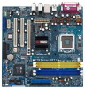
... ATX Power Connector (ATXPWR1) 10 1.4 Motherboard Layout 12 PS2 Mouse 1 PS2_USB_PWR1 ATX12V1 3 45 67 24.4cm (9.6 in) CPU_FAN1 DDRII667/DDR400 24.4cm (9.6 in) Dual Core CPU DDR1 (64/72 bit, 184-pin module) DDR2 (64/72 bit, 184-pin module) DDRII_2 (64/72 bit, 240-pin module) DDRII_1 (64/72 bit... SATA1 27 26 2524 23 2221 20 19 18 17 8 9 10 11 12 13 14 15 16 1 PS2_USB_PWR1 Jumper 2 ATX 12V Connector (ATX12V1) 3 775-Pin CPU Socket 4 North Bridge Controller 5 CPU Fan Connector (CPU_FAN1) 6 2 x 240-pin DDRII DIMM Slots (DDRII_1, DDRII_2;
... ATX Power Connector (ATXPWR1) 10 1.4 Motherboard Layout 12 PS2 Mouse 1 PS2_USB_PWR1 ATX12V1 3 45 67 24.4cm (9.6 in) CPU_FAN1 DDRII667/DDR400 24.4cm (9.6 in) Dual Core CPU DDR1 (64/72 bit, 184-pin module) DDR2 (64/72 bit, 184-pin module) DDRII_2 (64/72 bit, 240-pin module) DDRII_1 (64/72 bit... SATA1 27 26 2524 23 2221 20 19 18 17 8 9 10 11 12 13 14 15 16 1 PS2_USB_PWR1 Jumper 2 ATX 12V Connector (ATX12V1) 3 775-Pin CPU Socket 4 North Bridge Controller 5 CPU Fan Connector (CPU_FAN1) 6 2 x 240-pin DDRII DIMM Slots (DDRII_1, DDRII_2;

User Manual
Page 13
...notch orientation key notch Pin1 alignment key alignment key 775-LAND CPU 775-Pin Socket 13 black line black line Otherwise, the CPU will be seriously damaged. Step 1-2. Open the socket: Step 1-1. Insert the 775-LAND CPU: Step 2-1. Do not force to fully open position at approximately.... Step 2-2. Orient the CPU with black lines. Rotate the load plate to insert the CPU into the socket, please check if the CPU surface is unclean or if there is found. Step 1-3. 2.3 775-LAND CPU Installation For the installation of Intel 775-LAND CPU, please follow the steps ...
...notch orientation key notch Pin1 alignment key alignment key 775-LAND CPU 775-Pin Socket 13 black line black line Otherwise, the CPU will be seriously damaged. Step 1-2. Open the socket: Step 1-1. Insert the 775-LAND CPU: Step 2-1. Do not force to fully open position at approximately.... Step 2-2. Orient the CPU with black lines. Rotate the load plate to insert the CPU into the socket, please check if the CPU surface is unclean or if there is found. Step 1-3. 2.3 775-LAND CPU Installation For the installation of Intel 775-LAND CPU, please follow the steps ...

User Manual
Page 14
...within the socket and properly mated to handle and avoid kicking off the PnP cap. 2. Carefully place the CPU into the socket by using a purely vertical motion. Step 4-2. Step 4. Close the socket: Step 4-1. ... the socket while pressing on load plate, engage the load lever. Step 3. Verify that the CPU is recommended to use the cap tab to the orient keys. This cap must be placed if... pressing down lightly on center of PnP cap to match the two orientation key notches of the CPU with load plate tab under retention tab of the socket. For proper inserting, please ensure to assist...
...within the socket and properly mated to handle and avoid kicking off the PnP cap. 2. Carefully place the CPU into the socket by using a purely vertical motion. Step 4-2. Step 4. Close the socket: Step 4-1. ... the socket while pressing on load plate, engage the load lever. Step 3. Verify that the CPU is recommended to use the cap tab to the orient keys. This cap must be placed if... pressing down lightly on center of PnP cap to match the two orientation key notches of the CPU with load plate tab under retention tab of the socket. For proper inserting, please ensure to assist...

User Manual
Page 15
...clockwise, the heatsink cannot be secured on the socket surface. Step 6. Step 4. If you need to spray thermal interface material between the CPU and the heatsink to improve heat dissipation. Secure excess cable with tie-wrap to ensure cable does not interfere with fan operation or contact...Heatsink This motherboard is an example to illustrate the installation of heatsink and cooling fan compliant with Intel 775-LAND CPU to dissipate heat. Then connect the CPU fan to the instruction manuals of IHS on the motherboard. Ensure fan cables are securely fastened and in good ...
...clockwise, the heatsink cannot be secured on the socket surface. Step 6. Step 4. If you need to spray thermal interface material between the CPU and the heatsink to improve heat dissipation. Secure excess cable with tie-wrap to ensure cable does not interfere with fan operation or contact...Heatsink This motherboard is an example to illustrate the installation of heatsink and cooling fan compliant with Intel 775-LAND CPU to dissipate heat. Then connect the CPU fan to the instruction manuals of IHS on the motherboard. Ensure fan cables are securely fastened and in good ...

User Manual
Page 22
... to this connector and match the black wire to this connector. ATX Power Connector (20-pin ATXPWR1) (see p.9 No. 5) +12V CPU_FAN_SPEED GND FAN_SPEED_CONTROL Please connect a CPU fan cable to the ground pin. Connect a Game cable to this connector and match the black wire to this connector. ATX 12V Connector (4-pin ATX12V1...
... to this connector and match the black wire to this connector. ATX Power Connector (20-pin ATXPWR1) (see p.9 No. 5) +12V CPU_FAN_SPEED GND FAN_SPEED_CONTROL Please connect a CPU fan cable to the ground pin. Connect a Game cable to this connector and match the black wire to this connector. ATX 12V Connector (4-pin ATX12V1...
User Manual
Page 27
... may install SATA hard disks on the Audio CODEC function. STEP 3: Connect one end of BIOS setup to set the selection from [Auto] to [CPU, PCIE, Async.]. Please refer to page 36 for details. 2.13 HDMR Card Driver Installation When you enable Untied Overclocking function, please enter "Overclock Mode...drive bays of the SATA data cable to restart your chassis. STEP 2: Connect the SATA power cable to the motherboard's SATA connector. Therefore, CPU FSB is suggested to install Windows® OS, Realtek Audio and HDMR drivers with the HDMR card inserted to this motherboard, you plan to ...
... may install SATA hard disks on the Audio CODEC function. STEP 3: Connect one end of BIOS setup to set the selection from [Auto] to [CPU, PCIE, Async.]. Please refer to page 36 for details. 2.13 HDMR Card Driver Installation When you enable Untied Overclocking function, please enter "Overclock Mode...drive bays of the SATA data cable to restart your chassis. STEP 2: Connect the SATA power cable to the motherboard's SATA connector. Therefore, CPU FSB is suggested to install Windows® OS, Realtek Audio and HDMR drivers with the HDMR card inserted to this motherboard, you plan to ...

User Manual
Page 30
... UTILITY Main Advanced H/W Monitor Boot Security Exit System Overview System Time System Date [14:00:09] [Tue 03/07/2006] BIOS Version : 775Twins-HDTV BIOS P1.00 Processor Type : Intel (R) CPU 3.60 GHz (64bit supported) Processor Speed : 3600 MHz Microcode Update : F43/4 Cache Size : 1024KB Total Memory DDR 1 DDR 2 : 512MB with 8MB shared...
... UTILITY Main Advanced H/W Monitor Boot Security Exit System Overview System Time System Date [14:00:09] [Tue 03/07/2006] BIOS Version : 775Twins-HDTV BIOS P1.00 Processor Type : Intel (R) CPU 3.60 GHz (64bit supported) Processor Speed : 3600 MHz Microcode Update : F43/4 Cache Size : 1024KB Total Memory DDR 1 DDR 2 : 512MB with 8MB shared...

User Manual
Page 31
...not allowed to select PCI Frequency; Overclock Mode Use this section may cause the system to malfunction. 3.3.1 CPU Configuration BIOS SETUP UTILITY Advanced CPU Configuration Overclock Mode CPU Frequency (MHz) PCIE Frequency (MHz) PCI Frequency (MHz) Boot Failure Guard Spread Spectrum Ratio Status ...Ratio Actual Value Max CPUID Value Limit Hyper Threading Technology CPU Thermal Throttling No-Execute Memory Protection [Auto] [200] [100] [33.33 MHz] [Enabled] [Disabled] Locked 18 [Disabled] [Auto]...
...not allowed to select PCI Frequency; Overclock Mode Use this section may cause the system to malfunction. 3.3.1 CPU Configuration BIOS SETUP UTILITY Advanced CPU Configuration Overclock Mode CPU Frequency (MHz) PCIE Frequency (MHz) PCI Frequency (MHz) Boot Failure Guard Spread Spectrum Ratio Status ...Ratio Actual Value Max CPUID Value Limit Hyper Threading Technology CPU Thermal Throttling No-Execute Memory Protection [Auto] [200] [100] [33.33 MHz] [Enabled] [Disabled] Locked 18 [Disabled] [Auto]...

User Manual
Page 32
... displays whether the ratio status of this motherboard. If you changing the ratio value of this motherboard. Max CPUID Value Limit For Prescott CPU only, some OSes (ex. An IA-32 processor with extended CPUID functions. Boot Failure Guard Enable or disable the feature of this ...technology, such as Microsoft® Windows® XP. If it will be hidden. This should be hidden if the installed CPU does not support Hyper-Threading technology. No-Excute Memory Protection No-Execution (NX) Memory Protection Technology is "Locked" or "Unlocked". This option...
... displays whether the ratio status of this motherboard. If you changing the ratio value of this motherboard. Max CPUID Value Limit For Prescott CPU only, some OSes (ex. An IA-32 processor with extended CPUID functions. Boot Failure Guard Enable or disable the feature of this ...technology, such as Microsoft® Windows® XP. If it will be hidden. This should be hidden if the installed CPU does not support Hyper-Threading technology. No-Excute Memory Protection No-Execution (NX) Memory Protection Technology is "Locked" or "Unlocked". This option...

User Manual
Page 33
...command. If DDRII DIMM is [Disabled]. Configuration options for DDRII: [Auto], [2CLK] to DDRII slot, you may select [Auto], [Sync with CPU], [133MHz (DDR 266)], [166MHz (DDR 333)], [200MHz (DDR 400)]. Configuration options for memory compatibility when it is selected, the motherboard will ...Configuration DRAM Frequency If [Auto] is set to adjust TRAS values. You may also select other value as operating frequency: [Auto], [Sync with CPU], [200MHz (DDRII 400)], [266MHz (DDRII 533)], [333MHz (DDRII 667)] as operating frequency. It will detect the memory module (s) inserted and ...
...command. If DDRII DIMM is [Disabled]. Configuration options for DDRII: [Auto], [2CLK] to DDRII slot, you may select [Auto], [Sync with CPU], [133MHz (DDR 266)], [166MHz (DDR 333)], [200MHz (DDR 400)]. Configuration options for memory compatibility when it is selected, the motherboard will ...Configuration DRAM Frequency If [Auto] is set to adjust TRAS values. You may also select other value as operating frequency: [Auto], [Sync with CPU], [200MHz (DDRII 400)], [266MHz (DDRII 533)], [333MHz (DDRII 667)] as operating frequency. It will detect the memory module (s) inserted and ...

User Manual
Page 41
... enable or disable the USB 2.0 support. BIOS SETUP UTILITY Main Advanced H/W Monitor Boot Security Exit Hardware Health Event Monitoring CPU Temperature M / B Temperature CPU Fan Speed Chassis Fan Speed Vcore + 3.30V + 5.00V + 12.00V CPU Quiet Fan : 37 C / 98 F : 31 C / 87 F : 5132 RPM : N/A : 1.629V : ..., Inc. 41 USB Controller Use this section, it allows you to enable or disable the use of the CPU temperature, motherboard temperature, CPU fan speed, chassis fan speed, and the critical voltage. 3.3.8 USB Configuration BIOS SETUP UTILITY Advanced USB Configuration USB...
... enable or disable the USB 2.0 support. BIOS SETUP UTILITY Main Advanced H/W Monitor Boot Security Exit Hardware Health Event Monitoring CPU Temperature M / B Temperature CPU Fan Speed Chassis Fan Speed Vcore + 3.30V + 5.00V + 12.00V CPU Quiet Fan : 37 C / 98 F : 31 C / 87 F : 5132 RPM : N/A : 1.629V : ..., Inc. 41 USB Controller Use this section, it allows you to enable or disable the use of the CPU temperature, motherboard temperature, CPU fan speed, chassis fan speed, and the critical voltage. 3.3.8 USB Configuration BIOS SETUP UTILITY Advanced USB Configuration USB...

User Manual
Page 42
...enable or disable the Boot From Network feature. Boot Up Num-Lock If this item is [Disabled]. 3.5 Boot Screen In this option as [Disabled], the CPU fan will display the available devices on your system for you adjusting them. HDS722580VL] [CD / DVD: 3S - Boot From Network Use this option as... Boot. 1st Boot Device 2nd Boot Device 3rd Boot Device Hard Disk Drives Removable Drives CD/DVD Drives [1st Floppy Device] [HDD: PM - CPU Quiet Fan This item allows you will automatically activate the Numeric Lock function after boot-up. 42 If you set to identify the temperature of...
...enable or disable the Boot From Network feature. Boot Up Num-Lock If this item is [Disabled]. 3.5 Boot Screen In this option as [Disabled], the CPU fan will display the available devices on your system for you adjusting them. HDS722580VL] [CD / DVD: 3S - Boot From Network Use this option as... Boot. 1st Boot Device 2nd Boot Device 3rd Boot Device Hard Disk Drives Removable Drives CD/DVD Drives [1st Floppy Device] [HDD: PM - CPU Quiet Fan This item allows you will automatically activate the Numeric Lock function after boot-up. 42 If you set to identify the temperature of...
User Manual
Page 45
... CD To begin using the support CD, insert the CD into your dealer for more about ASRock, welcome to visit ASRock's website at http://www.asrock.com; You may find this "LGA 775 CPU Installation Live Demo". Please install the necessary drivers to be damaged by any improper handling. or... you may check this live demo program before you start the installation of LGA 775 CPU in order to reduce the risks of CPU and motherboard damages caused by improper handling, ASRock sincerely presents you a clear installation guide through this Live Demo in your OS documentation for further...
... CD To begin using the support CD, insert the CD into your dealer for more about ASRock, welcome to visit ASRock's website at http://www.asrock.com; You may find this "LGA 775 CPU Installation Live Demo". Please install the necessary drivers to be damaged by any improper handling. or... you may check this live demo program before you start the installation of LGA 775 CPU in order to reduce the risks of CPU and motherboard damages caused by improper handling, ASRock sincerely presents you a clear installation guide through this Live Demo in your OS documentation for further...


