
User Manual
Page 3
....... 24 2.10.2 TV Support Function 26 2.11 Untied Overclocking Technology 27 2.12 Serial ATA (SATA) Hard Disks Installation 27 2.13 HDMR Card Driver Installation 27 2.14 Making a SATA Driver Diskette For Windows® 2000 / XP / XP 64-bit / VistaTM Installation 28 3 BIOS SETUP UTILITY 29 3.1 Introduction 29 3.1.1 BIOS Menu Bar 29 3.1.2 Navigation Keys 30 3.2 Main Screen 30 3.3 Advanced Screen 31 3.3.1 CPU Configuration 31 3.3.2 Chipset Configuration 33 3.3.3 ACPI Configuration 35 3.3.4 IDE Configuration 36 3.3.5 PCIPnP Configuration 38 3.3.6 Floppy Configuration 39 3 Contents...
....... 24 2.10.2 TV Support Function 26 2.11 Untied Overclocking Technology 27 2.12 Serial ATA (SATA) Hard Disks Installation 27 2.13 HDMR Card Driver Installation 27 2.14 Making a SATA Driver Diskette For Windows® 2000 / XP / XP 64-bit / VistaTM Installation 28 3 BIOS SETUP UTILITY 29 3.1 Introduction 29 3.1.1 BIOS Menu Bar 29 3.1.2 Navigation Keys 30 3.2 Main Screen 30 3.3 Advanced Screen 31 3.3.1 CPU Configuration 31 3.3.2 Chipset Configuration 33 3.3.3 ACPI Configuration 35 3.3.4 IDE Configuration 36 3.3.5 PCIPnP Configuration 38 3.3.6 Floppy Configuration 39 3 Contents...

User Manual
Page 5
... Floppy Drive One Serial ATA (SATA) Data Cable (Optional) One Serial ATA (SATA) HDD Power Cable (Optional) One HD 8CH I/O Shield One HDMR Card (Optional) One ASRock VGA_HDTV Panel One VGA_2x8 Cable One AV/S_2x3 Cable 5 In this manual, chapter 1 and 2 contain introduction of the motherboard and step-by-step guide to quality and endurance. In case any modifications of this manual will be subject to BIOS setup and information of this manual occur, the updated version will...
... Floppy Drive One Serial ATA (SATA) Data Cable (Optional) One Serial ATA (SATA) HDD Power Cable (Optional) One HD 8CH I/O Shield One HDMR Card (Optional) One ASRock VGA_HDTV Panel One VGA_2x8 Cable One AV/S_2x3 Cable 5 In this manual, chapter 1 and 2 contain introduction of the motherboard and step-by-step guide to quality and endurance. In case any modifications of this manual will be subject to BIOS setup and information of this manual occur, the updated version will...

User Manual
Page 8
... the system or damage the CPU. 4. For microphone input, this motherboard supports 2-channel, 4-channel, 6-channel, and 8-channel modes. Besides, please enter BIOS setup Advanced Settings Chipset Configuration NorthBridge Configuration to set the option "Video Display Devices" to spray thermal grease between the CPU and the heatsink when you install the PC system. 5. While CPU overheat is recommended to use this motherboard offers stepless control, it is detected, the system will update it back again. Please check the table...
... the system or damage the CPU. 4. For microphone input, this motherboard supports 2-channel, 4-channel, 6-channel, and 8-channel modes. Besides, please enter BIOS setup Advanced Settings Chipset Configuration NorthBridge Configuration to set the option "Video Display Devices" to spray thermal grease between the CPU and the heatsink when you install the PC system. 5. While CPU overheat is recommended to use this motherboard offers stepless control, it is detected, the system will update it back again. Please check the table...

User Manual
Page 18
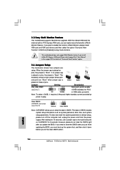
... Monitor Feature This motherboard supports Multi Monitor upgrade. Please refer to page 34 for 15 seconds, use a jumper cap to enable the function of Multi Monitor, please install VGA card and VGA card drivers and then select the option "Surround View Function" of "Surround View Function" option. 2.8 Jumpers Setup The illustration shows how jumpers are "Short" when jumper cap is "Short". When the jumper cap is placed on pins, the jumper is placed on PCI Express VGA card, you update the BIOS...
... Monitor Feature This motherboard supports Multi Monitor upgrade. Please refer to page 34 for 15 seconds, use a jumper cap to enable the function of Multi Monitor, please install VGA card and VGA card drivers and then select the option "Surround View Function" of "Surround View Function" option. 2.8 Jumpers Setup The illustration shows how jumpers are "Short" when jumper cap is "Short". When the jumper cap is placed on pins, the jumper is placed on PCI Express VGA card, you update the BIOS...

User Manual
Page 23
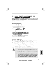
...-type component video connector (green) 2 PB-CON1: RCA-type component video connector (blue) / AV (composite) signal connector 3 PR-CON1: RCA-type component video connector (red) 4 VGA1: 25pin D-Sub (blue) for you to install the VGA driver correctly in Windows control panel or change BIOS setup, and you use. Step 3. 2.10 Installing VGA_HDTV Panel to Enjoy HDTV (HighDefinition TV) / TV Support Function Additional VGA_HDTV panel with VGA and 3 RCA-type component video output, that allows PC to connect to all high...
...-type component video connector (green) 2 PB-CON1: RCA-type component video connector (blue) / AV (composite) signal connector 3 PR-CON1: RCA-type component video connector (red) 4 VGA1: 25pin D-Sub (blue) for you to install the VGA driver correctly in Windows control panel or change BIOS setup, and you use. Step 3. 2.10 Installing VGA_HDTV Panel to Enjoy HDTV (HighDefinition TV) / TV Support Function Additional VGA_HDTV panel with VGA and 3 RCA-type component video output, that allows PC to connect to all high...
User Manual
Page 27
... SATA data cable to the motherboard's SATA connector. If you install the drivers to your computer, then the Audio CODEC can operate under a more stable overclocking environment. 2.12 Serial ATA (SATA) Hard Disks Installation This motherboard adopts ULi® 1573 southbridge chipset that supports Serial ATA (SATA) hard disks and RAID functions (RAID 0, 1, 0+1, JBOD). in ATA Combination Mode enabled. However, if you enable Untied Overclocking function, please enter "Overclock Mode" option of the SATA data cable to [CPU, PCIE, Async.]. STEP 4: Connect the other drivers installation...
... SATA data cable to the motherboard's SATA connector. If you install the drivers to your computer, then the Audio CODEC can operate under a more stable overclocking environment. 2.12 Serial ATA (SATA) Hard Disks Installation This motherboard adopts ULi® 1573 southbridge chipset that supports Serial ATA (SATA) hard disks and RAID functions (RAID 0, 1, 0+1, JBOD). in ATA Combination Mode enabled. However, if you enable Untied Overclocking function, please enter "Overclock Mode" option of the SATA data cable to [CPU, PCIE, Async.]. STEP 4: Connect the other drivers installation...

User Manual
Page 32
... a computer system with disable. Spread Spectrum The default value of this motherboard. CPU Thermal Throttling You may select [Enabled] to enable P4 CPU internal thermal control mechanism to boot legacy OSes that includes optimization for this option is an enhancement to the core speed of Boot Failure Guard. This should be hidden if the installed CPU does not support Hyper-Threading technology. No-Excute Memory Protection No-Execution (NX) Memory Protection Technology is [Auto].
... a computer system with disable. Spread Spectrum The default value of this motherboard. CPU Thermal Throttling You may select [Enabled] to enable P4 CPU internal thermal control mechanism to boot legacy OSes that includes optimization for this option is an enhancement to the core speed of Boot Failure Guard. This should be hidden if the installed CPU does not support Hyper-Threading technology. No-Excute Memory Protection No-Execution (NX) Memory Protection Technology is [Auto].

User Manual
Page 34
... no external VGA card inserted or the PCIE VGA card you to select video display devices. The default value is [Auto]. Configuration options: [Auto], [High], [Normal], and [Low]. Configuration options: [Auto], [16MB], [32MB], [64MB], and [128MB]. If you install the PCIE VGA card and select [Enabled], the onboard VGA will switch the PCI Bus scanning order while searching for DDRII: [Auto], [0CLK] to [7CLK]. Configuration options for DDR: [Auto], [0CLK] to [3CLK]. The default value is [Auto]. The default value is [Auto]. NB Core Voltage Use this feature...
... no external VGA card inserted or the PCIE VGA card you to select video display devices. The default value is [Auto]. Configuration options: [Auto], [High], [Normal], and [Low]. Configuration options: [Auto], [16MB], [32MB], [64MB], and [128MB]. If you install the PCIE VGA card and select [Enabled], the onboard VGA will switch the PCI Bus scanning order while searching for DDRII: [Auto], [0CLK] to [7CLK]. Configuration options for DDR: [Auto], [0CLK] to [3CLK]. The default value is [Auto]. The default value is [Auto]. NB Core Voltage Use this feature...

User Manual
Page 36
... devices will only connect to secondary channel, SATA devices will work as [Enabled], the options OnBoard IDE Controller, OnBoard SATA Controller, and SATA Class Code will include ACPI High Precision Event Timer Table for OS if you set the power state after an unexpected AC/ Power loss. ACPI HPET Table Use this item to enable or disable PS/2 keyboard to boot up when the power recovers. BOTH: enables both IDE Controllers. +F1 F9 F10 ESC Select Screen Select Item Change Option General Help Load Defaults Save...
... devices will only connect to secondary channel, SATA devices will work as [Enabled], the options OnBoard IDE Controller, OnBoard SATA Controller, and SATA Class Code will include ACPI High Precision Event Timer Table for OS if you set the power state after an unexpected AC/ Power loss. ACPI HPET Table Use this item to enable or disable PS/2 keyboard to boot up when the power recovers. BOTH: enables both IDE Controllers. +F1 F9 F10 ESC Select Screen Select Item Change Option General Help Load Defaults Save...

User Manual
Page 37
...-5 :Supported [Auto] [Auto] [Auto] [Auto] [Auto] [Disabled] [Enabled] Select the type of device connected to configure the type of the IDE device that you can be applied to active. 37 TYPE Use this item to the system. +F1 F9 F10 ESC Select Screen Select Item Change Option General Help Load Defaults Save and Exit Exit v02.54 (C) Copyright 1985-2005, American Megatrends, Inc. OnBoard SATA Controller Use this to automatically detect the hard disk drive. Configuration options: [AHCI], [RAID]. BIOS SETUP UTILITY Advanced Primary IDE Master Device Vendor Size...
...-5 :Supported [Auto] [Auto] [Auto] [Auto] [Auto] [Disabled] [Enabled] Select the type of device connected to configure the type of the IDE device that you can be applied to active. 37 TYPE Use this item to the system. +F1 F9 F10 ESC Select Screen Select Item Change Option General Help Load Defaults Save and Exit Exit v02.54 (C) Copyright 1985-2005, American Megatrends, Inc. OnBoard SATA Controller Use this to automatically detect the hard disk drive. Configuration options: [AHCI], [RAID]. BIOS SETUP UTILITY Advanced Primary IDE Master Device Vendor Size...

User Manual
Page 38
... the hard disk timing. Configuration options: [Disabled], [Auto], [Enabled]. 32-Bit Data Transfer Use this item to enable 32-bit access to maximize the IDE hard disk data transfer rate. 3.3.5 PCIPnP Configuration BIOS SETUP UTILITY Advanced Advanced PCI / PnP Settings PCI Latency Timer PCI IDE BusMaster [32] [Enabled] Value in units of this item to keep the default value unless the installed PCI expansion cards' specifications require other settings. Use this item is [Auto]. PCI IDE BusMaster Use this item to select the LBA/Large mode for compatible IDE devices...
... the hard disk timing. Configuration options: [Disabled], [Auto], [Enabled]. 32-Bit Data Transfer Use this item to enable 32-bit access to maximize the IDE hard disk data transfer rate. 3.3.5 PCIPnP Configuration BIOS SETUP UTILITY Advanced Advanced PCI / PnP Settings PCI Latency Timer PCI IDE BusMaster [32] [Enabled] Value in units of this item to keep the default value unless the installed PCI expansion cards' specifications require other settings. Use this item is [Auto]. PCI IDE BusMaster Use this item to select the LBA/Large mode for compatible IDE devices...
User Manual
Page 45
... 775 CPU in this live demo program before you may check this chapter for further information. 45 Because motherboard settings and hardware options vary, use the setup procedures in order to activate the devices. 4.2.3 Utilities Menu The Utilities Menu shows the applications software that Intel has released. Chapter 4 Software Support 4.1 Install Operating System This motherboard supports various Microsoft® Windows® operating systems: 2000 / XP / XP 64-bit / VistaTM...
... 775 CPU in this live demo program before you may check this chapter for further information. 45 Because motherboard settings and hardware options vary, use the setup procedures in order to activate the devices. 4.2.3 Utilities Menu The Utilities Menu shows the applications software that Intel has released. Chapter 4 Software Support 4.1 Install Operating System This motherboard supports various Microsoft® Windows® operating systems: 2000 / XP / XP 64-bit / VistaTM...
Quick Installation Guide
Page 7
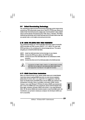
... website in the support CD. 2. While CPU overheat is detected, the system will update it is not ready yet. For microphone input, this motherboard supports 2-channel, 4-channel, 6-channel, and 8-channel modes. Besides, please enter BIOS setup Advanced Settings Chipset Configuration NorthBridge Configuration to set the option "Video Display Devices" to use VGA mode instead of TV-OUT mode. ASRock website http://www.asrock.com 7 ASRock 775Twins-HDTV Motherboard English Frequencies other than the recommended CPU bus frequencies may cause the instability of "User Manual" in the future...
... website in the support CD. 2. While CPU overheat is detected, the system will update it is not ready yet. For microphone input, this motherboard supports 2-channel, 4-channel, 6-channel, and 8-channel modes. Besides, please enter BIOS setup Advanced Settings Chipset Configuration NorthBridge Configuration to set the option "Video Display Devices" to use VGA mode instead of TV-OUT mode. ASRock website http://www.asrock.com 7 ASRock 775Twins-HDTV Motherboard English Frequencies other than the recommended CPU bus frequencies may cause the instability of "User Manual" in the future...
Quick Installation Guide
Page 14
... This motherboard supports Multi Monitor upgrade. If you update the BIOS. Please refer to default setup, please turn off the computer and unplug the power cord from the power supply. Clear CMOS (CLRCMOS1, 3-pin jumper) (see p.2 No. 1) +5VSB (standby) for 5 seconds. With the onboard VGA and the external add-on these 2 pins. When the jumper cap is placed on pins, the jumper is Short Open placed on PCI Express VGA card, you must boot up events. English 14 ASRock 775Twins-HDTV Motherboard...
... This motherboard supports Multi Monitor upgrade. If you update the BIOS. Please refer to default setup, please turn off the computer and unplug the power cord from the power supply. Clear CMOS (CLRCMOS1, 3-pin jumper) (see p.2 No. 1) +5VSB (standby) for 5 seconds. With the onboard VGA and the external add-on these 2 pins. When the jumper cap is placed on pins, the jumper is Short Open placed on PCI Express VGA card, you must boot up events. English 14 ASRock 775Twins-HDTV Motherboard...
Quick Installation Guide
Page 17
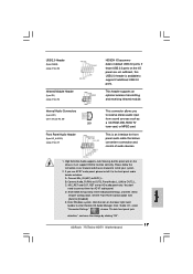
... front panel audio header as a CD-ROM, DVD-ROM, TV tuner card, or MPEG card. USB 2.0 Header (9-pin USB45) (see p.2 No. 20) Infrared Module Header (5-pin IR1) (see p.2 No. 25) Internal Audio Connectors (4-pin CD1) (CD1: see p.2 No. 29) Front Panel Audio Header (9-pin HD_AUDIO1) (see p.2 No. 27) CD1 HD 8CH I /O", select "Connector Settings" , choose "Disable front panel jack detection", and save the change by clicking "OK". 17 ASRock 775Twins-HDTV Motherboard You don't need to [Enabled]. Set the Front Panel Control option from sound sources...
... front panel audio header as a CD-ROM, DVD-ROM, TV tuner card, or MPEG card. USB 2.0 Header (9-pin USB45) (see p.2 No. 20) Infrared Module Header (5-pin IR1) (see p.2 No. 25) Internal Audio Connectors (4-pin CD1) (CD1: see p.2 No. 29) Front Panel Audio Header (9-pin HD_AUDIO1) (see p.2 No. 27) CD1 HD 8CH I /O", select "Connector Settings" , choose "Disable front panel jack detection", and save the change by clicking "OK". 17 ASRock 775Twins-HDTV Motherboard You don't need to [Enabled]. Set the Front Panel Control option from sound sources...
Quick Installation Guide
Page 19
... high-definition TV with component video input capability (YPbPr) or TV with AV input capability. Step 3. After installing the VGA driver to install the VGA driver correctly in Windows control panel or change BIOS setup, and you use. Therefore, if you only install HDTV or TV instead of VGA monitor, it is , if you install the stand alone HDTV, TV, or VGA monitor before your computer to the computer, this motherboard. ASRock VGA_HDTV Layout 1 Y-CON1: RCA-type...
... high-definition TV with component video input capability (YPbPr) or TV with AV input capability. Step 3. After installing the VGA driver to install the VGA driver correctly in Windows control panel or change BIOS setup, and you use. Therefore, if you only install HDTV or TV instead of VGA monitor, it is , if you install the stand alone HDTV, TV, or VGA monitor before your computer to the computer, this motherboard. ASRock VGA_HDTV Layout 1 Y-CON1: RCA-type...
Quick Installation Guide
Page 23
... BIOS setup to set the selection from [Auto] to this motherboard, please install the Realtek Audio driver again; English 23 ASRock 775Twins-HDTV Motherboard This section will not work successfully. It is no problem on this motherboard, you install the drivers to use RAID 0, RAID 1, RAID 0+1, or JBOD functions on SATA, SATA HDDs must not operate in ATA Combination Mode enabled. otherwise, the Audio CODEC will guide you u enable Untied Overclocking function, please enter "Overclock Mode" option of the SATA data cable to this motherboard; If you install Windows...
... BIOS setup to set the selection from [Auto] to this motherboard, please install the Realtek Audio driver again; English 23 ASRock 775Twins-HDTV Motherboard This section will not work successfully. It is no problem on this motherboard, you install the drivers to use RAID 0, RAID 1, RAID 0+1, or JBOD functions on SATA, SATA HDDs must not operate in ATA Combination Mode enabled. otherwise, the Audio CODEC will guide you u enable Untied Overclocking function, please enter "Overclock Mode" option of the SATA data cable to this motherboard; If you install Windows...
Quick Installation Guide
Page 25
... designed to enter BIOS Setup utility; BIOS Information The Flash Memory on the system chassis. Software Support CD information This motherboard supports various Microsoft® Windows® operating systems: 2000/ XP/XP 64-bit/VistaTM. 3. If you a clear installation guide through the following path: ..\ MPEGAV \ LGA775INST.DAT 25 ASRock 775Twins-HDTV Motherboard English The Support CD that came with the motherboard contains necessary drivers and useful utilities that will display the Main Menu automatically if "AUTORUN" is a new CPU socket interface...
... designed to enter BIOS Setup utility; BIOS Information The Flash Memory on the system chassis. Software Support CD information This motherboard supports various Microsoft® Windows® operating systems: 2000/ XP/XP 64-bit/VistaTM. 3. If you a clear installation guide through the following path: ..\ MPEGAV \ LGA775INST.DAT 25 ASRock 775Twins-HDTV Motherboard English The Support CD that came with the motherboard contains necessary drivers and useful utilities that will display the Main Menu automatically if "AUTORUN" is a new CPU socket interface...
RAID Installation Guide
Page 20
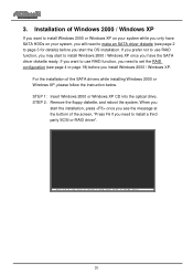
... use RAID function, you may start to install a third party SCSI or RAID driver . . . 20 STEP 1: Insert Windows 2000 or Windows XP CD into the optical drive. If you want to install Windows 2000 or Windows XP on your system while you only have SATA HDDs on your system, you will need to set the RAID configuration (see page 4 to page 19) before you need to install Windows 2000 / Windows...
... use RAID function, you may start to install a third party SCSI or RAID driver . . . 20 STEP 1: Insert Windows 2000 or Windows XP CD into the optical drive. If you want to install Windows 2000 or Windows XP on your system while you only have SATA HDDs on your system, you will need to set the RAID configuration (see page 4 to page 19) before you need to install Windows 2000 / Windows...
RAID Installation Guide
Page 21
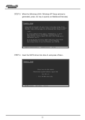
... type of one or more mass storage devices installed in your system, or you have any device support disks from a mass storage device manufacturer, press S. PS=reSspsecFi6fy iAf dydoituionnaeledDetvoiceinstalEl NaTEthRi=rdCopnatirntyue SCSFI 3=orExRitAID driver . . . STEP 4: Insert the SATA driver into Drive A: Press ENTER when ready. PErNeTssERF=6Coifntiynouue neeEdSCto=Cinanstcaell a Fth3i=rdExpitarty SCSI or RAID driver . . . 21 To specify additional SCSI adapters, CD-ROM drives, or special disk controllers for use with Windows...
... type of one or more mass storage devices installed in your system, or you have any device support disks from a mass storage device manufacturer, press S. PS=reSspsecFi6fy iAf dydoituionnaeledDetvoiceinstalEl NaTEthRi=rdCopnatirntyue SCSFI 3=orExRitAID driver . . . STEP 4: Insert the SATA driver into Drive A: Press ENTER when ready. PErNeTssERF=6Coifntiynouue neeEdSCto=Cinanstcaell a Fth3i=rdExpitarty SCSI or RAID driver . . . 21 To specify additional SCSI adapters, CD-ROM drives, or special disk controllers for use with Windows...


