User Manual
Page 3
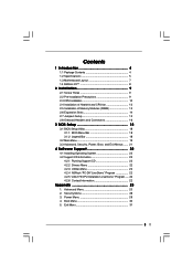
...1 Introduction 4 1.1 Package Contents 4 1.2 Specifications 5 1.3 Motherboard Layout 7 1.4 ASRock I/OTM 8 2 Installation 9 2.1 Screw Holes 9 2.2 Pre-installation Precautions 9 2.3 CPU Installation 10 2.4 Installation of Heatsink and CPU fan 12 2.5 Installation of Memory Modules (DIMM 13 2.6 Expansion Slots 14 2.7 ... ...... 21 4 Software Support 22 4.1 Installing Operating System 22 4.2 Support CD Information 22 4.2.1 Running Support CD 22 4.2.2 Drivers Menu 22 4.2.3 Utilities Menu 22 4.2.4 ASRock "PC-DIY Live Demo" Program 22 4.2.5 "LGA 775 CPU Installation Live Demo" Program...
...1 Introduction 4 1.1 Package Contents 4 1.2 Specifications 5 1.3 Motherboard Layout 7 1.4 ASRock I/OTM 8 2 Installation 9 2.1 Screw Holes 9 2.2 Pre-installation Precautions 9 2.3 CPU Installation 10 2.4 Installation of Heatsink and CPU fan 12 2.5 Installation of Memory Modules (DIMM 13 2.6 Expansion Slots 14 2.7 ... ...... 21 4 Software Support 22 4.1 Installing Operating System 22 4.2 Support CD Information 22 4.2.1 Running Support CD 22 4.2.2 Drivers Menu 22 4.2.3 Utilities Menu 22 4.2.4 ASRock "PC-DIY Live Demo" Program 22 4.2.5 "LGA 775 CPU Installation Live Demo" Program...
User Manual
Page 4
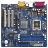
... of the motherboard and step-bystep installation guide for new DIY system builders. ASRock website http://www.asrock.com 1.1 Package Contents ASRock 775S61 Motherboard (Micro ATX Form Factor: 9.6-in x 9.0-in, 24.4 cm x 22.9 cm) ASRock 775S61 Quick Installation Guide ASRock 775S61 Support CD (including LGA 775 CPU Installation Live Demo) One 80-conductor Ultra ATA 66/100/133 IDE Ribbon...
... of the motherboard and step-bystep installation guide for new DIY system builders. ASRock website http://www.asrock.com 1.1 Package Contents ASRock 775S61 Motherboard (Micro ATX Form Factor: 9.6-in x 9.0-in, 24.4 cm x 22.9 cm) ASRock 775S61 Quick Installation Guide ASRock 775S61 Support CD (including LGA 775 CPU Installation Live Demo) One 80-conductor Ultra ATA 66/100/133 IDE Ribbon...
User Manual
Page 5
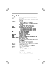
... card (see CAUTION 3) AMR slot: 1 slot, supports ASRock MR card USB 2.0: 6 USB 2.0 ports: includes 4 default USB 2.0 ports on the rear panel, plus one header to 2 floppy disk drives Audio: 6 channels AC'97 Audio LAN: Speed: 802.3u (10/100 Ethernet), supports Wake-On-LAN Hardware Monitor: CPU temperature sensing; PC2700 (DDR333) for 1 DDR DIMM...
... card (see CAUTION 3) AMR slot: 1 slot, supports ASRock MR card USB 2.0: 6 USB 2.0 ports: includes 4 default USB 2.0 ports on the rear panel, plus one header to 2 floppy disk drives Audio: 6 channels AC'97 Audio LAN: Speed: 802.3u (10/100 Ethernet), supports Wake-On-LAN Hardware Monitor: CPU temperature sensing; PC2700 (DDR333) for 1 DDR DIMM...
User Manual
Page 6
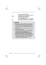
...clocks, such as PCI clock, AGP clock and Memory clock will automatically shutdown. CPU frequency stepless control (only for USB 2.0 works fine under Microsoft® Windows® 98/ME. Although 775S61 offers stepless control, it is not recommended to Microsoft® official document at ...5. Supports "Plug and Play"; It may cause permanent damage! 4. Audio Jack: Line Out / Line In / Microphone + Game port AMI legal BIOS; While CPU overheat is set to spray thermal grease between the CPU and the heatsink when you resume the system. When the CPU frequency of 775S61 is...
...clocks, such as PCI clock, AGP clock and Memory clock will automatically shutdown. CPU frequency stepless control (only for USB 2.0 works fine under Microsoft® Windows® 98/ME. Although 775S61 offers stepless control, it is not recommended to Microsoft® official document at ...5. Supports "Plug and Play"; It may cause permanent damage! 4. Audio Jack: Line Out / Line In / Microphone + Game port AMI legal BIOS; While CPU overheat is set to spray thermal grease between the CPU and the heatsink when you resume the system. When the CPU frequency of 775S61 is...
User Manual
Page 11
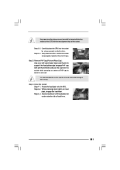
... lever with the two alignment keys of the socket. Remove PnP Cap (Pick and Place Cap): Use your left hand index finger and thumb to support the load plate edge, engage PnP cap with right hand thumb and peel the cap from the socket while pressing on load plate, engage the... cap. Step 4. While pressing down lightly on center of PnP cap to assist in removal. Rotate the load plate onto the IHS. Carefully place the CPU into the socket by using a purely vertical motion. Step 4-2. Step 4-3. Step 2-3. Close the socket: Step 4-1. For proper inserting, please ensure to match the two ...
... lever with the two alignment keys of the socket. Remove PnP Cap (Pick and Place Cap): Use your left hand index finger and thumb to support the load plate edge, engage PnP cap with right hand thumb and peel the cap from the socket while pressing on load plate, engage the... cap. Step 4. While pressing down lightly on center of PnP cap to assist in removal. Rotate the load plate onto the IHS. Carefully place the CPU into the socket by using a purely vertical motion. Step 4-2. Step 4-3. Step 2-3. Close the socket: Step 4-1. For proper inserting, please ensure to match the two ...
User Manual
Page 12
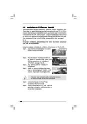
...3. Place the heatsink onto the socket. Repeat with Intel 775-Pin CPU to the CPU fan connector on the motherboard. Connect fan header with fan operation or contact other . Ensure that supports Intel 775-Pin CPU. Below is equipped with the motherboard throughholes. Ensure fan cables are ...securely fastened and in good contact with thumb to illustrate the installation of your CPU fan and heatsink. Secure excess cable with tie...
...3. Place the heatsink onto the socket. Repeat with Intel 775-Pin CPU to the CPU fan connector on the motherboard. Connect fan header with fan operation or contact other . Ensure that supports Intel 775-Pin CPU. Below is equipped with the motherboard throughholes. Ensure fan cables are ...securely fastened and in good contact with thumb to illustrate the installation of your CPU fan and heatsink. Secure excess cable with tie...
User Manual
Page 17
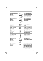
...) Chassis speaker connector (4-pin SPEAKER 1) (see p.7 No. 2) RRXD1 DDTR#1 DDSR#1 CCTS#1 1 RRI#1 RRTS#1 GND TTXD1 DDCD#1 This COM1 connector supports a serial port module. Connect an ATX power supply to the chassis speaker. This connector allows you to attach to the connector. Please note that it... L GND A U D - Failing to do so will cause the failure to the ground pin. This connector accommodates several system front panel functions. CPU fan connector (4-pin CPU_FAN1) (see p.7 item 5) ATX power connector (20-pin ATXPWR1) (see p.7 item 11) GND +12V CHA_FAN_SPEED Connect the ...
...) Chassis speaker connector (4-pin SPEAKER 1) (see p.7 No. 2) RRXD1 DDTR#1 DDSR#1 CCTS#1 1 RRI#1 RRTS#1 GND TTXD1 DDCD#1 This COM1 connector supports a serial port module. Connect an ATX power supply to the chassis speaker. This connector allows you to attach to the connector. Please note that it... L GND A U D - Failing to do so will cause the failure to the ground pin. This connector accommodates several system front panel functions. CPU fan connector (4-pin CPU_FAN1) (see p.7 item 5) ATX power connector (20-pin ATXPWR1) (see p.7 item 11) GND +12V CHA_FAN_SPEED Connect the ...
User Manual
Page 22
....DAT To see this "LGA 775 CPU Installation Live Demo". Since it . 4.2.4 ASRock PC-DIY Live Demo Program ASRock presents you a multimedia PC-DIY live demo program before you may check this Live Demo in the Support CD to reduce the risks of CPU and motherboard damages caused by step. ...detects installed devices. Refer to your dealer for more about ASRock, welcome to know more information. 4.2 Support CD Information The Support CD that came with Intel LGA 775 socket, which is a new CPU socket interface that the motherboard supports. Click on the file "ASSETUP.EXE" from the "BIN...
....DAT To see this "LGA 775 CPU Installation Live Demo". Since it . 4.2.4 ASRock PC-DIY Live Demo Program ASRock presents you a multimedia PC-DIY live demo program before you may check this Live Demo in the Support CD to reduce the risks of CPU and motherboard damages caused by step. ...detects installed devices. Refer to your dealer for more about ASRock, welcome to know more information. 4.2 Support CD Information The Support CD that came with Intel LGA 775 socket, which is a new CPU socket interface that the motherboard supports. Click on the file "ASSETUP.EXE" from the "BIN...
User Manual
Page 23
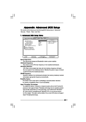
...Pentium®4 processor that supports Hyper-Threading technology and an operating system that times the front side bus frequency will be [Disabled] for this feature, it is determined by the installed processor. This option will equal the core speed of spread spectrum. CPU Ratio Selection: CPU Ratio is selected, the... Values Enter:Select Sub-Menu F9:Setup Defaults F10:Save & Exit Spread Spectrum: This field should always be hidden if the current CPU does not support Hyper-Threading technology. 23 Advanced BIOS Setup Menu Main Advanced AMIBIOS SETUP UTILITY -
...Pentium®4 processor that supports Hyper-Threading technology and an operating system that times the front side bus frequency will be [Disabled] for this feature, it is determined by the installed processor. This option will equal the core speed of spread spectrum. CPU Ratio Selection: CPU Ratio is selected, the... Values Enter:Select Sub-Menu F9:Setup Defaults F10:Save & Exit Spread Spectrum: This field should always be hidden if the current CPU does not support Hyper-Threading technology. 23 Advanced BIOS Setup Menu Main Advanced AMIBIOS SETUP UTILITY -
User Manual
Page 24
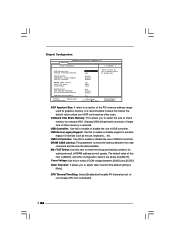
... Chipset Configuration [ Setup Help ] AGP Aperture Size Onboard VGA Share Memory USB Controller USB Device Legacy Support USB 2.0 Controller DRAM CAS# Latency MA 1T/2T Select Vccm Voltage Defer Function CPU Thermal Throttling No-Excute Memory Protection AGP / PCI Fix Frequency F1:Help Esc:Previous Menu :Select Item... memory. Defer Function: It allows you to enable or disable the use of DRAM address/control signals. USB Device Legacy Support: Use this to select the size of share memory for optimized result of USB controller. USB 2.0 Controller: Use this to enable or ...
... Chipset Configuration [ Setup Help ] AGP Aperture Size Onboard VGA Share Memory USB Controller USB Device Legacy Support USB 2.0 Controller DRAM CAS# Latency MA 1T/2T Select Vccm Voltage Defer Function CPU Thermal Throttling No-Excute Memory Protection AGP / PCI Fix Frequency F1:Help Esc:Previous Menu :Select Item... memory. Defer Function: It allows you to enable or disable the use of DRAM address/control signals. USB Device Legacy Support: Use this to select the size of share memory for optimized result of USB controller. USB 2.0 Controller: Use this to enable or ...
User Manual
Page 25
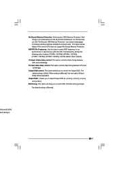
...], [+0.2ns], [+0.4ns], and [+0.6ns]. P4 input strobe delay control: This option controls strobe timing between CPU and northbridge. When setting is [Manual], the next option [Output DQS] will be hidden if the current CPU does not support No-Excute Memory Protection. No-Excute Memory Protection: No-Execution (NX) Memory Protection Tech nology is...
...], [+0.2ns], [+0.4ns], and [+0.6ns]. P4 input strobe delay control: This option controls strobe timing between CPU and northbridge. When setting is [Manual], the next option [Output DQS] will be hidden if the current CPU does not support No-Excute Memory Protection. No-Excute Memory Protection: No-Execution (NX) Memory Protection Tech nology is...


