User Manual
Page 3
...5. Exit Menu 31 3 Advanced Menu 23 2. Security Menu 28 3. Contents 1 Introduction 4 1.1 Package Contents 4 1.2 Specifications 5 1.3 Motherboard Layout 7 1.4 ASRock I/OTM 8 2 Installation 9 2.1 Screw Holes 9 2.2 Pre-installation Precautions 9 2.3 CPU Installation 10 2.4 Installation of Heatsink and CPU fan... System 22 4.2 Support CD Information 22 4.2.1 Running Support CD 22 4.2.2 Drivers Menu 22 4.2.3 Utilities Menu 22 4.2.4 ASRock "PC-DIY Live Demo" Program 22 4.2.5 "LGA 775 CPU Installation Live Demo" Program...... 22 4.2.6 Contact Information 22 Appendix 23 1. Power ...
...5. Exit Menu 31 3 Advanced Menu 23 2. Security Menu 28 3. Contents 1 Introduction 4 1.1 Package Contents 4 1.2 Specifications 5 1.3 Motherboard Layout 7 1.4 ASRock I/OTM 8 2 Installation 9 2.1 Screw Holes 9 2.2 Pre-installation Precautions 9 2.3 CPU Installation 10 2.4 Installation of Heatsink and CPU fan... System 22 4.2 Support CD Information 22 4.2.1 Running Support CD 22 4.2.2 Drivers Menu 22 4.2.3 Utilities Menu 22 4.2.4 ASRock "PC-DIY Live Demo" Program 22 4.2.5 "LGA 775 CPU Installation Live Demo" Program...... 22 4.2.6 Contact Information 22 Appendix 23 1. Power ...
User Manual
Page 4
... Live Demo) One 80-conductor Ultra ATA 66/100/133 IDE Ribbon Cable One Ribbon Cable for purchasing ASRock 775S61 motherboard, a reliable motherboard produced under ASRock's consistently stringent quality control. You may find the latest memory and CPU support lists on page 23 offers... more advanced BIOS setup information. ASRock website http://www.asrock.com 1.1 Package Contents ASRock 775S61 Motherboard (Micro ATX Form Factor: 9.6-in x 9.0-in Floppy Drive One ASRock I/OTM Shield One COM Port Bracket One ASRock MR Card (Optional) 4 Chapter 1 and 2 of this...
... Live Demo) One 80-conductor Ultra ATA 66/100/133 IDE Ribbon Cable One Ribbon Cable for purchasing ASRock 775S61 motherboard, a reliable motherboard produced under ASRock's consistently stringent quality control. You may find the latest memory and CPU support lists on page 23 offers... more advanced BIOS setup information. ASRock website http://www.asrock.com 1.1 Package Contents ASRock 775S61 Motherboard (Micro ATX Form Factor: 9.6-in x 9.0-in Floppy Drive One ASRock I/OTM Shield One COM Port Bracket One ASRock MR Card (Optional) 4 Chapter 1 and 2 of this...
User Manual
Page 6
.... Supports "Plug and Play"; Do NOT use a 3.3V AGP card on the motherboard functions properly before you install the PC system. 3. It may cause permanent damage! 4. About the setting of 775S61 motherboard! Frequencies other clocks, such as PCI clock, AGP clock and Memory clock will automatically...than the recommended CPU bus frequencies may cause the instability of the system or damage the CPU and the motherboard. 6 ACPI 1.1 compliance wake up events; Although 775S61 offers stepless control, it is set to spray thermal grease between the CPU and the heatsink when you resume...
.... Supports "Plug and Play"; Do NOT use a 3.3V AGP card on the motherboard functions properly before you install the PC system. 3. It may cause permanent damage! 4. About the setting of 775S61 motherboard! Frequencies other clocks, such as PCI clock, AGP clock and Memory clock will automatically...than the recommended CPU bus frequencies may cause the instability of the system or damage the CPU and the motherboard. 6 ACPI 1.1 compliance wake up events; Although 775S61 offers stepless control, it is set to spray thermal grease between the CPU and the heatsink when you resume...
User Manual
Page 7
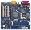
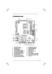
1.3 Motherboard Layout 12 34 5 6 22.9cm (9.0 in) PS/2 Mouse PS2_USB_PWR1 1 PS/2 Keyboard ATX12V1 CPU_FAN1 7 VGA PARALLEL PORT ATXPWR1 ` Prescott 800 DDR400 FSB800 DDR DIMM1 (64/72 ... AAUUDDIIOO11 Line out LiLInnineein MMIniicc in 2Mb BIOS Super I/O LAN PHY CD1 AUX1 AUDIO1 1 JR1 JL1 AUDIO CODEC AMR1 SIS 661FX Chipset 1.5V_AGP1 PCI 1 PCI 2 775S61 PCI 3 FLOPPY1 01 23 45 IDE2 IDE1 ATA133 SIS 963L USB45 1 5.1CH USB2.0 1 CMOS Battery CHA_FAN1 1 COM1 IR1 SPEAKER1 1 PANEL 1 PLED PWRBTN 1 HDLED RST 20...
1.3 Motherboard Layout 12 34 5 6 22.9cm (9.0 in) PS/2 Mouse PS2_USB_PWR1 1 PS/2 Keyboard ATX12V1 CPU_FAN1 7 VGA PARALLEL PORT ATXPWR1 ` Prescott 800 DDR400 FSB800 DDR DIMM1 (64/72 ... AAUUDDIIOO11 Line out LiLInnineein MMIniicc in 2Mb BIOS Super I/O LAN PHY CD1 AUX1 AUDIO1 1 JR1 JL1 AUDIO CODEC AMR1 SIS 661FX Chipset 1.5V_AGP1 PCI 1 PCI 2 775S61 PCI 3 FLOPPY1 01 23 45 IDE2 IDE1 ATA133 SIS 963L USB45 1 5.1CH USB2.0 1 CMOS Battery CHA_FAN1 1 COM1 IR1 SPEAKER1 1 PANEL 1 PLED PWRBTN 1 HDLED RST 20...
User Manual
Page 9
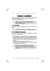
... or touch a safety grounded object before you install or remove any component. 2. Before you install motherboard components or change any component, place it . Chapter 2 Installation 775S61 is detached from the wall socket before installing or removing the motherboard. Before you install the motherboard, study the configuration of the following precautions before you uninstall any...
... or touch a safety grounded object before you install or remove any component. 2. Before you install motherboard components or change any component, place it . Chapter 2 Installation 775S61 is detached from the wall socket before installing or removing the motherboard. Before you install the motherboard, study the configuration of the following precautions before you uninstall any...
User Manual
Page 12
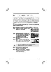
... Secure excess cable with tie-wrap to ensure cable does not interfere with remaining fasteners. 2.4 Installation of CPU Fan and Heatsink This motherboard is an example to illustrate the installation of the heatsink for 775-Pin CPU. Please adopt the type of your CPU fan and ... operation or contact other . Rotate the fastener clockwise, then press down the fasteners without rotating them clockwise, the heatsink cannot be secured on the motherboard (CPU_FAN1, see page 7, No. 5). Step 5. Ensure that supports Intel 775-Pin CPU. Step 4. Then connect the CPU fan to install ...
... Secure excess cable with tie-wrap to ensure cable does not interfere with remaining fasteners. 2.4 Installation of CPU Fan and Heatsink This motherboard is an example to illustrate the installation of the heatsink for 775-Pin CPU. Please adopt the type of your CPU fan and ... operation or contact other . Rotate the fastener clockwise, then press down the fasteners without rotating them clockwise, the heatsink cannot be secured on the motherboard (CPU_FAN1, see page 7, No. 5). Step 5. Ensure that supports Intel 775-Pin CPU. Step 4. Then connect the CPU fan to install ...
User Manual
Page 13
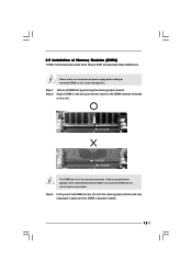
... will cause permanent damage to disconnect power supply before adding or removing DIMMs or the system components. Step 3. Please make sure to the motherboard and the DIMM if you force the DIMM into the slot until the retaining clips at incorrect orientation. Step 1. 2.5 Installation of Memory Modules ...(DIMM) 775S61 motherboard provides three 184-pin DDR (Double Data Rate) DIMM slots. Firmly insert the DIMM into the slot at both ends fully snap back in...
... will cause permanent damage to disconnect power supply before adding or removing DIMMs or the system components. Step 3. Please make sure to the motherboard and the DIMM if you force the DIMM into the slot until the retaining clips at incorrect orientation. Step 1. 2.5 Installation of Memory Modules ...(DIMM) 775S61 motherboard provides three 184-pin DDR (Double Data Rate) DIMM slots. Firmly insert the DIMM into the slot at both ends fully snap back in...
User Manual
Page 14
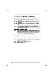
...supply is switched off or the power cord is AGP 3.5 compliant and it supports an 8X / 4X AGP card. Fasten the card to insert an ASRock MR card with v.92 Modem functionality. AMR slot: The AMR slot is used to use. Do NOT use . Replace the system cover. 14 It... AGP slot is unplugged. Remove the bracket facing the slot that you start the installation. Step 4. Remove the system unit cover (if your motherboard is completely seated on 775S61 motherboard. Installing an expansion card Step 1. PCI slots: The PCI slots are 3 PCI slots, 1 AMR slot, and 1 AGP slot on the slot. ...
...supply is switched off or the power cord is AGP 3.5 compliant and it supports an 8X / 4X AGP card. Fasten the card to insert an ASRock MR card with v.92 Modem functionality. AMR slot: The AMR slot is used to use. Do NOT use . Replace the system cover. 14 It... AGP slot is unplugged. Remove the bracket facing the slot that you start the installation. Step 4. Remove the system unit cover (if your motherboard is completely seated on 775S61 motherboard. Installing an expansion card Step 1. PCI slots: The PCI slots are 3 PCI slots, 1 AMR slot, and 1 AGP slot on the slot. ...
User Manual
Page 16
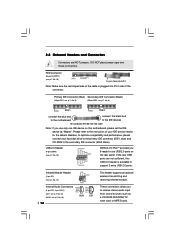
... the cable is available to -use only one IDE device on the rear panel. 2.8 Onboard Headers and Connectors Connectors are not sufficient, this motherboard, please set the IDE device as a CD-ROM, DVD-ROM, TV tuner card, or MPEG card. If the rear USB ports are NOT... jumpers. FDD Connector (33-pin FLOPPY1) (see p.7, No. 16) USB_PWR P-5 P+5 GND DUMMY 1 GND P+4 P-4 USB_PWR ASRock I/O PlusTM provides you 6 ready-to support 2 extra USB 2.0 ports. USB 2.0 Header (9-pin USB45) (see p.7, No. 19) Pin1 FLOPPY1 the red-striped side to ...
... the cable is available to -use only one IDE device on the rear panel. 2.8 Onboard Headers and Connectors Connectors are not sufficient, this motherboard, please set the IDE device as a CD-ROM, DVD-ROM, TV tuner card, or MPEG card. If the rear USB ports are NOT... jumpers. FDD Connector (33-pin FLOPPY1) (see p.7, No. 16) USB_PWR P-5 P+5 GND DUMMY 1 GND P+4 P-4 USB_PWR ASRock I/O PlusTM provides you 6 ready-to support 2 extra USB 2.0 ports. USB 2.0 Header (9-pin USB45) (see p.7, No. 19) Pin1 FLOPPY1 the red-striped side to ...
User Manual
Page 18
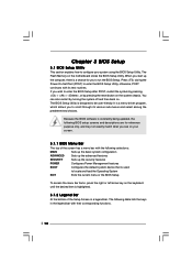
... what you to enter the BIOS Setup after POST, restart the system by pressing + + , or by turning the system off and then back on the motherboard stores the BIOS Setup Utility. It is constantly being updated, the following table lists the keys in the legend bar with their corresponding functions. 18...
... what you to enter the BIOS Setup after POST, restart the system by pressing + + , or by turning the system off and then back on the motherboard stores the BIOS Setup Utility. It is constantly being updated, the following table lists the keys in the legend bar with their corresponding functions. 18...
User Manual
Page 22
... file "ASSETUP.EXE" from the "BIN" folder in order to visit ASRock's website at http://www.asrock.com; or you can run Microsoft® Media Player® to play the file. Because motherboard settings and hardware options vary, use the setup procedures in your own PC... system step by improper handling, ASRock sincerely presents you how to your CD-ROM drive. Chapter 4 Software Support 4.1 Install Operating System This motherboard supports various Microsoft® Windows® operating systems: 98 SE / ME / 2000 /...
... file "ASSETUP.EXE" from the "BIN" folder in order to visit ASRock's website at http://www.asrock.com; or you can run Microsoft® Media Player® to play the file. Because motherboard settings and hardware options vary, use the setup procedures in your own PC... system step by improper handling, ASRock sincerely presents you how to your CD-ROM drive. Chapter 4 Software Support 4.1 Install Operating System This motherboard supports various Microsoft® Windows® operating systems: 98 SE / ME / 2000 /...
User Manual
Page 23
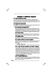
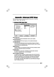
... detect the memory module(s) inserted and assigns appropriate frequency automatically. DRAM Frequency: If [Auto] is selected, the motherboard will equal the core speed of spread spectrum. Flexibility Option: The default value of the installed motherboard. VERSION 3.31a Security Power Boot Exit Spread Spectrum CPU Host Frequency Actual Frequency CPU Ratio Selection DRAM...
... detect the memory module(s) inserted and assigns appropriate frequency automatically. DRAM Frequency: If [Auto] is selected, the motherboard will equal the core speed of spread spectrum. Flexibility Option: The default value of the installed motherboard. VERSION 3.31a Security Power Boot Exit Spread Spectrum CPU Host Frequency Actual Frequency CPU Ratio Selection DRAM...
User Manual
Page 27
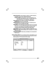
... can check the status of the parallel port. Midi IRQ Select: Use this option is [ECP+EPP]. OnBoard Midi Port: Select address for CPU temperature, Motherboard temperature, CPU fan speed, and critical voltage. Or you to select Midi IRQ. The default value is set to [Disabled] will show the EPP version...
... can check the status of the parallel port. Midi IRQ Select: Use this option is [ECP+EPP]. OnBoard Midi Port: Select address for CPU temperature, Motherboard temperature, CPU fan speed, and critical voltage. Or you to select Midi IRQ. The default value is set to [Disabled] will show the EPP version...

