User Manual
Page 3
... Contents 4 1.2 Specifications 5 1.3 Motherboard Layout 7 1.4 ASRock I/OTM 8 2 Installation 9 2.1 Screw Holes 9 2.2 Pre-installation Precautions 9 2.3 CPU Installation 10 2.4 Installation of Heatsink and CPU fan 12 2.5 Installation of Memory Modules (DIMM 13 2.6 Expansion Slots 14 2.7 Jumpers Setup 15 2.8 Onboard Headers and Connectors 16 3 BIOS Setup 18 3.1 BIOS Setup Utility 18 3.1.1 BIOS Menu Bar 18 3.1.2 Legend Bar 18 3.2 Main Menu 19 3.3 Advanced, Security, Power, Boot, and Exit Menus ...... 21 4 Software Support 22 4.1 Installing Operating System 22 4.2 Support CD...
... Contents 4 1.2 Specifications 5 1.3 Motherboard Layout 7 1.4 ASRock I/OTM 8 2 Installation 9 2.1 Screw Holes 9 2.2 Pre-installation Precautions 9 2.3 CPU Installation 10 2.4 Installation of Heatsink and CPU fan 12 2.5 Installation of Memory Modules (DIMM 13 2.6 Expansion Slots 14 2.7 Jumpers Setup 15 2.8 Onboard Headers and Connectors 16 3 BIOS Setup 18 3.1 BIOS Setup Utility 18 3.1.1 BIOS Menu Bar 18 3.1.2 Legend Bar 18 3.2 Main Menu 19 3.3 Advanced, Security, Power, Boot, and Exit Menus ...... 21 4 Software Support 22 4.1 Installing Operating System 22 4.2 Support CD...
User Manual
Page 4
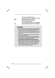
... ASRock's commitment to change without further notice. Because the motherboard specifications and the BIOS software might be updated, the content of this manual occur, the updated version will be available on ASRock website without notice. Chapter 1 Introduction Thank you for a 3.5-in Floppy Drive One ASRock I/OTM Shield One COM Port Bracket One ASRock MR Card (Optional) 4 You may find the latest memory and CPU support lists on page 23 offers more advanced BIOS setup...
... ASRock's commitment to change without further notice. Because the motherboard specifications and the BIOS software might be updated, the content of this manual occur, the updated version will be available on ASRock website without notice. Chapter 1 Introduction Thank you for a 3.5-in Floppy Drive One ASRock I/OTM Shield One COM Port Bracket One ASRock MR Card (Optional) 4 You may find the latest memory and CPU support lists on page 23 offers more advanced BIOS setup...
User Manual
Page 5
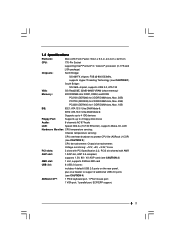
... PC2100 (DDR266) for 3 DDR DIMM slots, Max. 3GB; Supports up to 4 IDE devices Floppy Port: Supports up to 2 floppy disk drives Audio: 6 channels AC'97 Audio LAN: Speed: 802.3u (10/100 Ethernet), supports Wake-On-LAN Hardware Monitor: CPU temperature sensing; Chassis fan tachometer; Chassis temperature sensing; PC3200 (DDR400) for 2 DDR DIMM slots, Max. 2GB; 1.2 Specifications Platform: Micro ATX Form Factor: 9.6-in x 9.0-in, 24.4 cm x 22.9 cm CPU: 775-Pin Socket supporting Intel® Pentium® 4 / Celeron® processor (in 775-land LGA package...
... PC2100 (DDR266) for 3 DDR DIMM slots, Max. 3GB; Supports up to 4 IDE devices Floppy Port: Supports up to 2 floppy disk drives Audio: 6 channels AC'97 Audio LAN: Speed: 802.3u (10/100 Ethernet), supports Wake-On-LAN Hardware Monitor: CPU temperature sensing; Chassis fan tachometer; Chassis temperature sensing; PC3200 (DDR400) for 2 DDR DIMM slots, Max. 2GB; 1.2 Specifications Platform: Micro ATX Form Factor: 9.6-in x 9.0-in, 24.4 cm x 22.9 cm CPU: 775-Pin Socket supporting Intel® Pentium® 4 / Celeron® processor (in 775-land LGA package...
User Manual
Page 6
... recommended CPU bus frequencies may cause the instability of 775S61 motherboard! It may not work properly under Microsoft® Windows® XP SP1/2000 SP4. Power Management for advanced users' reference, see CAUTION 5) Microsoft® Windows® 98SE / ME / 2000 / XP compliant CAUTION! 1. Please refer to perform over clocking. Audio Jack: Line Out / Line In / Microphone + Game port AMI legal BIOS; CPU frequency stepless control (only for USB 2.0 works...
... recommended CPU bus frequencies may cause the instability of 775S61 motherboard! It may not work properly under Microsoft® Windows® XP SP1/2000 SP4. Power Management for advanced users' reference, see CAUTION 5) Microsoft® Windows® 98SE / ME / 2000 / XP compliant CAUTION! 1. Please refer to perform over clocking. Audio Jack: Line Out / Line In / Microphone + Game port AMI legal BIOS; CPU frequency stepless control (only for USB 2.0 works...
User Manual
Page 7
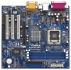
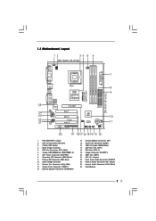
...-Pin CPU Socket 4 North Bridge Controller 5 CPU Fan Connector (CPU_FAN1) 6 184-pin DDR DIMM Slots (DDR DIMM1- 3) 7 ATX Power Connector (ATXPWR1) 8 Secondary IDE Connector (IDE2, Black) 9 Primary IDE Connector (IDE1, Blue) 10 South Bridge Controller 11 Chassis Fan Connector (CHA_FAN1) 12 System Panel Connector (PANEL1) 13 External Speaker Connector (SPEAKER1) 14 Infrared Module Connector (IR1) 15 Serial Port Connector (COM1) 16 USB 2.0 Header (USB45, Blue) 17 AGP Slot (1.5V_AGP1) 18 PCI Slots (PCI1- 3) 19 Floppy Connector (FLOPPY1) 20 AMR Slot (AMR1) 21 JR1 / JL1 Jumpers 22 Front Panel Audio...
...-Pin CPU Socket 4 North Bridge Controller 5 CPU Fan Connector (CPU_FAN1) 6 184-pin DDR DIMM Slots (DDR DIMM1- 3) 7 ATX Power Connector (ATXPWR1) 8 Secondary IDE Connector (IDE2, Black) 9 Primary IDE Connector (IDE1, Blue) 10 South Bridge Controller 11 Chassis Fan Connector (CHA_FAN1) 12 System Panel Connector (PANEL1) 13 External Speaker Connector (SPEAKER1) 14 Infrared Module Connector (IR1) 15 Serial Port Connector (COM1) 16 USB 2.0 Header (USB45, Blue) 17 AGP Slot (1.5V_AGP1) 18 PCI Slots (PCI1- 3) 19 Floppy Connector (FLOPPY1) 20 AMR Slot (AMR1) 21 JR1 / JL1 Jumpers 22 Front Panel Audio...
User Manual
Page 9
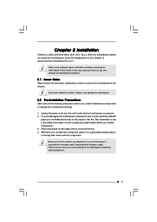
... it on the carpet or the like. Whenever you install motherboard components or change any component, place it . Unplug the power cord from the wall socket before you uninstall any motherboard settings. 1. Failure to do not touch the ICs. 4. Chapter 2 Installation 775S61 is detached from the power supply. Before you install the motherboard, study the configuration of the following precautions before touching any component, ensure...
... it on the carpet or the like. Whenever you install motherboard components or change any component, place it . Unplug the power cord from the wall socket before you uninstall any motherboard settings. 1. Failure to do not touch the ICs. 4. Chapter 2 Installation 775S61 is detached from the power supply. Before you install the motherboard, study the configuration of the following precautions before touching any component, ensure...
User Manual
Page 12
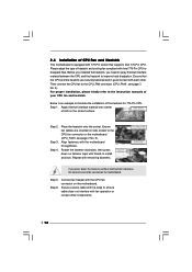
... connect the CPU fan to improve heat dissipation. Step 3. Place the heatsink onto the socket. Before you installed the heatsink, you press down on fastener caps with tie-wrap to the CPU fan connector on side closest to ensure cable does not interfere with 775-Pin socket that the CPU and the heatsink are securely fastened and in good contact with the motherboard throughholes. Step 1. Ensure fan cables...
... connect the CPU fan to improve heat dissipation. Step 3. Place the heatsink onto the socket. Before you installed the heatsink, you press down on fastener caps with tie-wrap to the CPU fan connector on side closest to ensure cable does not interfere with 775-Pin socket that the CPU and the heatsink are securely fastened and in good contact with the motherboard throughholes. Step 1. Ensure fan cables...
User Manual
Page 16
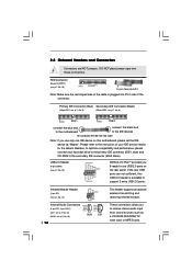
.../133 cable Note: If you to -use only one IDE device on the rear panel. 2.8 Onboard Headers and Connectors Connectors are not sufficient, this motherboard, please set the IDE device as a CD-ROM, DVD-ROM, TV tuner card, or MPEG card. These connectors allow you use USB 2.0 ports on this USB 2.0 header is plugged into Pin1 side of your hard disk drive to the primary IDE connector (IDE1, blue) and CD-ROM to the instruction of the connector. Please refer to the secondary IDE connector...
.../133 cable Note: If you to -use only one IDE device on the rear panel. 2.8 Onboard Headers and Connectors Connectors are not sufficient, this motherboard, please set the IDE device as a CD-ROM, DVD-ROM, TV tuner card, or MPEG card. These connectors allow you use USB 2.0 ports on this USB 2.0 header is plugged into Pin1 side of your hard disk drive to the primary IDE connector (IDE1, blue) and CD-ROM to the instruction of the connector. Please refer to the secondary IDE connector...
User Manual
Page 17
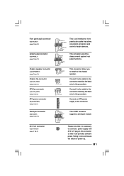
... convenient connection and control of audio devices. Chassis fan connector (3-pin CHA_FAN1) (see p.7 No. 2) RRXD1 DDTR#1 DDSR#1 CCTS#1 1 RRI#1 RRTS#1 GND TTXD1 DDCD#1 This COM1 connector supports a serial port module. Serial port connector (9-pin COM1) (see p.7 item 15) ATX 12V Connector (4-pin ATX12V1) (see p.7 item 11) GND +12V CHA_FAN_SPEED Connect the fan cable to the connector matching the black wire to the ground pin. Failing to do so will cause the failure to the chassis speaker. O U T- This connector accommodates...
... convenient connection and control of audio devices. Chassis fan connector (3-pin CHA_FAN1) (see p.7 No. 2) RRXD1 DDTR#1 DDSR#1 CCTS#1 1 RRI#1 RRTS#1 GND TTXD1 DDCD#1 This COM1 connector supports a serial port module. Serial port connector (9-pin COM1) (see p.7 item 15) ATX 12V Connector (4-pin ATX12V1) (see p.7 item 11) GND +12V CHA_FAN_SPEED Connect the fan cable to the connector matching the black wire to the ground pin. Failing to do so will cause the failure to the chassis speaker. O U T- This connector accommodates...
User Manual
Page 18
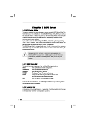
... you start up the security features POWER Configures Power Management features BOOT Configures the default system device that is used to locate and load the Operating System EXIT Exits the current menu or the BIOS Setup To access the menu bar items, press the right or left arrow key on the motherboard stores the BIOS Setup Utility. If you wish to enter the BIOS Setup after POST, restart the system by pressing + + , or by turning the...
... you start up the security features POWER Configures Power Management features BOOT Configures the default system device that is used to locate and load the Operating System EXIT Exits the current menu or the BIOS Setup To access the menu bar items, press the right or left arrow key on the motherboard stores the BIOS Setup Utility. If you wish to enter the BIOS Setup after POST, restart the system by pressing + + , or by turning the...
User Manual
Page 19
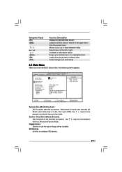
... and Year fields. Main Advanced System Date System Time Floppy Drives IDE Devices BIOS Version Processor Type Processor Speed Cache Size Microcode Update Total Memory DDR1 DDR2 DDR3 AMIBIOS SETUP UTILITY - Valid values for month, day, and year are Month: (Jan to Dec), Day: (1 to 31), Year: (up a selected menu for a highlighted field Loads all the setup items to default value Saves changes and exits Setup 3.2 Main Menu When you specify. Use keys to 2099). Dec...
... and Year fields. Main Advanced System Date System Time Floppy Drives IDE Devices BIOS Version Processor Type Processor Speed Cache Size Microcode Update Total Memory DDR1 DDR2 DDR3 AMIBIOS SETUP UTILITY - Valid values for month, day, and year are Month: (Jan to Dec), Day: (1 to 31), Year: (up a selected menu for a highlighted field Loads all the setup items to default value Saves changes and exits Setup 3.2 Main Menu When you specify. Use keys to 2099). Dec...
User Manual
Page 21
... This is used to configure the number of cylinders. Fast Programmed I/O Modes This allows user to set the PIO mode to determine the correct value. [CD/DVD]: This is used for IDE CD/DVD drives. [ARMD]: This is used for IDE ARMD (ATAPI Removable Media Device), such as calculated by the BIOS based on the drive information you entered. Refer to the drive documentation to enhance hard disk performance by reading...
... This is used to configure the number of cylinders. Fast Programmed I/O Modes This allows user to set the PIO mode to determine the correct value. [CD/DVD]: This is used for IDE CD/DVD drives. [ARMD]: This is used for IDE ARMD (ATAPI Removable Media Device), such as calculated by the BIOS based on the drive information you entered. Refer to the drive documentation to enhance hard disk performance by reading...
User Manual
Page 22
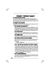
... may contact your CD-ROM drive. or you may check this chapter for further information. 22 Because motherboard settings and hardware options vary, use the setup procedures in the Support CD to play the file. 4.2.5 "LGA 775 CPU Installation Live Demo" Program This motherboard is a new CPU socket interface that the motherboard supports. If the Main Menu did not appear automatically, locate and double click on a specific item then follow...
... may contact your CD-ROM drive. or you may check this chapter for further information. 22 Because motherboard settings and hardware options vary, use the setup procedures in the Support CD to play the file. 4.2.5 "LGA 775 CPU Installation Live Demo" Program This motherboard is a new CPU socket interface that the motherboard supports. If the Main Menu did not appear automatically, locate and double click on a specific item then follow...
User Manual
Page 23
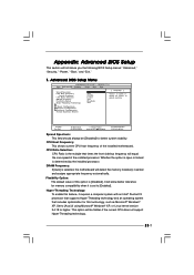
... the installed processor. Whether the option is open or locked is set to [Enabled]. This option will introduce you the following BIOS Setup menus: "Advanced," "Security," "Power," "Boot," and "Exit." 1. Appendix: Advanced BIOS Setup This section will be [Disabled] for better system stability. VERSION 3.31a Security Power Boot Exit Spread Spectrum CPU Host Frequency Actual Frequency CPU Ratio Selection DRAM Frequency Flexibility Option Hyper-Threading Technology Disabled Auto 200MHz Locked Auto [Disabled] Auto [ Setup Help ] to [Auto] if using Microsoft® Windows®...
... the installed processor. Whether the option is open or locked is set to [Enabled]. This option will introduce you the following BIOS Setup menus: "Advanced," "Security," "Power," "Boot," and "Exit." 1. Appendix: Advanced BIOS Setup This section will be [Disabled] for better system stability. VERSION 3.31a Security Power Boot Exit Spread Spectrum CPU Host Frequency Actual Frequency CPU Ratio Selection DRAM Frequency Flexibility Option Hyper-Threading Technology Disabled Auto 200MHz Locked Auto [Disabled] Auto [ Setup Help ] to [Auto] if using Microsoft® Windows®...
User Manual
Page 24
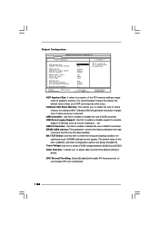
...graphics memory. DRAM CAS# Latency: This parameter controls the latency between [2.62V] and [2.55V]. VERSION 3.31a Chipset Configuration [ Setup Help ] AGP Aperture Size Onboard VGA Share Memory USB Controller USB Device Legacy Support USB 2.0 Controller DRAM CAS# Latency MA 1T/2T Select Vccm Voltage Defer Function CPU Thermal Throttling No-Excute Memory Protection AGP / PCI Fix Frequency F1:Help Esc:Previous Menu :Select Item 64MB Auto Enabled Disabled Enabled Auto MA2T 2.62V Auto Enabled Enabled Sync. +/-:Change Values Enter:Select Sub-Menu to enable or disable the use...
...graphics memory. DRAM CAS# Latency: This parameter controls the latency between [2.62V] and [2.55V]. VERSION 3.31a Chipset Configuration [ Setup Help ] AGP Aperture Size Onboard VGA Share Memory USB Controller USB Device Legacy Support USB 2.0 Controller DRAM CAS# Latency MA 1T/2T Select Vccm Voltage Defer Function CPU Thermal Throttling No-Excute Memory Protection AGP / PCI Fix Frequency F1:Help Esc:Previous Menu :Select Item 64MB Auto Enabled Disabled Enabled Auto MA2T 2.62V Auto Enabled Enabled Sync. +/-:Change Values Enter:Select Sub-Menu to enable or disable the use...
User Manual
Page 26
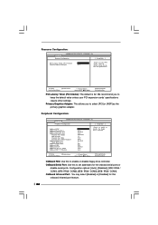
... Select OnBoard Game Port OnBoard IDE OnBoard LAN OnBoard AC' 97 Audio OnBoard MC' 97 Modem Auto Auto Disabled Auto ECP+EPP 1.9 Auto Auto Disabled 5 200 Both Enabled Auto Auto to select PCI clocks. VERSION 3.31a Resource Configuration [ Setup Help ] PCI Latency Timer (PCI Clocks) 32 Primary Graphics Adapter PCI to enable or disable the floppy drive controller. Leave on default setting for this to enable or disable floppy drive controller. F1:Help Esc:Previous Menu :Select Item +/-:Change Values Enter:Select Sub-Menu F9:Setup Defaults F10:Save & Exit OnBoard FDC: Use...
... Select OnBoard Game Port OnBoard IDE OnBoard LAN OnBoard AC' 97 Audio OnBoard MC' 97 Modem Auto Auto Disabled Auto ECP+EPP 1.9 Auto Auto Disabled 5 200 Both Enabled Auto Auto to select PCI clocks. VERSION 3.31a Resource Configuration [ Setup Help ] PCI Latency Timer (PCI Clocks) 32 Primary Graphics Adapter PCI to enable or disable the floppy drive controller. Leave on default setting for this to enable or disable floppy drive controller. F1:Help Esc:Previous Menu :Select Item +/-:Change Values Enter:Select Sub-Menu F9:Setup Defaults F10:Save & Exit OnBoard FDC: Use...
User Manual
Page 27
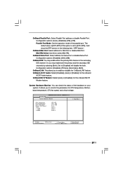
... Midi Port or disable Midi Port. It allows you to enable or disable the "OnBoard LAN" feature. OnBoard Game Port: Select address for CPU temperature, Motherboard temperature, CPU fan speed, and critical voltage. Advanced AMIBIOS SETUP UTILITY - OnBoard Parallel Port: Select Parallel Port address or disable Parallel Port. Or you to monitor the parameters for Game Port or disable Game Port. Parallel Port Mode: Set the operation mode of the hardware on your system. Midi IRQ Select: Use this option is [ECP+EPP]. The default...
... Midi Port or disable Midi Port. It allows you to enable or disable the "OnBoard LAN" feature. OnBoard Game Port: Select address for CPU temperature, Motherboard temperature, CPU fan speed, and critical voltage. Advanced AMIBIOS SETUP UTILITY - OnBoard Parallel Port: Select Parallel Port address or disable Parallel Port. Or you to monitor the parameters for Game Port or disable Game Port. Parallel Port Mode: Set the operation mode of the hardware on your system. Midi IRQ Select: Use this option is [ECP+EPP]. The default...
User Manual
Page 28
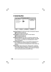
...BIOS setup. Security Setup Menu Main Advanced AMIBIOS SETUP UTILITY - Set Supervisor Password: Press to create a new password. If you already have a password, you must enter your current password first in order to 6 alphanumeric characters combination. Set User Password: Press to set the supervisor password. Password Check: Select the check point for "Password Check". 2. Configuration options: [Setup], [Always]. VERSION 3.31a Security Power Boot Exit Supervisor Password User Password Set Supervisor Password Set User Password Clear Clear [ Enter ] [ Enter ] [ Setup...
...BIOS setup. Security Setup Menu Main Advanced AMIBIOS SETUP UTILITY - Set Supervisor Password: Press to create a new password. If you already have a password, you must enter your current password first in order to 6 alphanumeric characters combination. Set User Password: Press to set the supervisor password. Password Check: Select the check point for "Password Check". 2. Configuration options: [Setup], [Always]. VERSION 3.31a Security Power Boot Exit Supervisor Password User Password Set Supervisor Password Set User Password Clear Clear [ Enter ] [ Enter ] [ Setup...
User Manual
Page 29
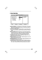
... the actual wake up when the power recovers. PS/2 Keyboard Power On: Use this feature if the system supports it. F1:Help Esc:Exit :Select Item :Select Menu +/-:Change Values Enter:Select Sub-Menu F9:Setup Defaults F10:Save & Exit Suspend to RAM (S3): This field allows you to turn on the system. If [Power On] is recommended to enable this to enable or disable PCI devices to set the power state...
... the actual wake up when the power recovers. PS/2 Keyboard Power On: Use this feature if the system supports it. F1:Help Esc:Exit :Select Item :Select Menu +/-:Change Values Enter:Select Sub-Menu F9:Setup Defaults F10:Save & Exit Suspend to RAM (S3): This field allows you to turn on the system. If [Power On] is recommended to enable this to enable or disable PCI devices to set the power state...
User Manual
Page 30
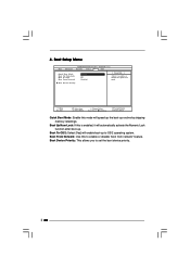
...: If this mode will enable boot-up routine by skipping memory retestings. Boot Device Priority: This allows you to enable or disable the quick boot mode. VERSION 3.31a Security Power Boot Exit Quick Boot Mode Boot Up Num-Lock Boot To OS/2 Boot From Network Enabled On No Disabled [ Setup Help ] to set the boot device priority. 30 4. Boot Setup Menu Main Advanced AMIBIOS SETUP UTILITY - Boot To OS/2: Select [Yes] will speed up the boot-up to enable or disable "boot from network" feature. Boot From Network: Use this to...
...: If this mode will enable boot-up routine by skipping memory retestings. Boot Device Priority: This allows you to enable or disable the quick boot mode. VERSION 3.31a Security Power Boot Exit Quick Boot Mode Boot Up Num-Lock Boot To OS/2 Boot From Network Enabled On No Disabled [ Setup Help ] to set the boot device priority. 30 4. Boot Setup Menu Main Advanced AMIBIOS SETUP UTILITY - Boot To OS/2: Select [Yes] will speed up the boot-up to enable or disable "boot from network" feature. Boot From Network: Use this to...


