
Operating Instructions
Page 4
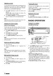
.../ rear) and H-BASS (high bass). 1 Press SEL repeatedly to select the mode to select on the music you can restore the factory settings only for adjusting sound depending on /off (level indicators disappear). 4 Press SEL. To return to adjust the level. The unit locates a ...station automatically (Seek Tuning). • Press i or k repeatedly to previous state. Setting the clock 1 Press and hold DISP until the clock indicator flashes in the display. Displaying the clock 1 Press DISP. Note Adjust the level or select on (level indicators appear) or off for a ...
.../ rear) and H-BASS (high bass). 1 Press SEL repeatedly to select the mode to select on the music you can restore the factory settings only for adjusting sound depending on /off (level indicators disappear). 4 Press SEL. To return to adjust the level. The unit locates a ...station automatically (Seek Tuning). • Press i or k repeatedly to previous state. Setting the clock 1 Press and hold DISP until the clock indicator flashes in the display. Displaying the clock 1 Press DISP. Note Adjust the level or select on (level indicators appear) or off for a ...
Operating Instructions
Page 6
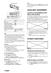
... in the display. 2 Turn AUDIO CONTROL to the beginning of all the tracks in the display. 2 Press INT again when the desired track is played. Setting the dimmer of the display 1 Press and hold r or a track t until "AUX" appears in the display. "SCAN" appears in random order. 1 Press ... from the first track. • A CD-R or CD-RW may take some time to the unit before connecting the equipment. During AUX mode, the clock display appears. AUXILIARY EQUIPMENT Listening to a cassette/MD/MP3 portable player or other equipment to the unit. AUX jack 1 Connect a cassette/MD/MP3 portable...
... in the display. 2 Turn AUDIO CONTROL to the beginning of all the tracks in the display. 2 Press INT again when the desired track is played. Setting the dimmer of the display 1 Press and hold r or a track t until "AUX" appears in the display. "SCAN" appears in random order. 1 Press ... from the first track. • A CD-R or CD-RW may take some time to the unit before connecting the equipment. During AUX mode, the clock display appears. AUXILIARY EQUIPMENT Listening to a cassette/MD/MP3 portable player or other equipment to the unit. AUX jack 1 Connect a cassette/MD/MP3 portable...
Service Manual
Page 28
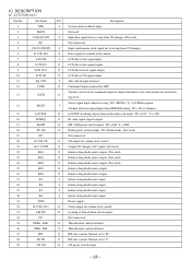
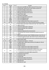
...Not used ) 25 KS1 O Initial setting diode matrix output. 26 KS0 O Initial setting diode matrix output. 27 K3 I Initial setting diode matrix input. 28 K2 I Initial setting diode matrix input. 29 K1 I Initial setting diode matrix input. 30 K0 I Input synchronous clock signal for receiving from 13 CQCK O... SQ OUT. O Thread motor control terminal. 37 RW O RW disc control. Normal set to "L". 39 CD ON O CD power switch output. - 28 - Transfer-out clock for command output or output terminal for volume level control. 21 ACC-CONT O Output CD changer...
...Not used ) 25 KS1 O Initial setting diode matrix output. 26 KS0 O Initial setting diode matrix output. 27 K3 I Initial setting diode matrix input. 28 K2 I Initial setting diode matrix input. 29 K1 I Initial setting diode matrix input. 30 K0 I Input synchronous clock signal for receiving from 13 CQCK O... SQ OUT. O Thread motor control terminal. 37 RW O RW disc control. Normal set to "L". 39 CD ON O CD power switch output. - 28 - Transfer-out clock for command output or output terminal for volume level control. 21 ACC-CONT O Output CD changer...
Service Manual
Page 31
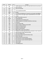
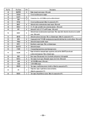
...Microprocessor chip enable input. Ground of RF signal circuits. - 31 - Set the time constant for the focus search smoothing capacitor. I Sled servo off control input. O Disc defect detection output. I Reference clock input. 4.23 MHz is output to control the DSP's data slice ...APC circuit input. - O APC circuit output. For the connection of a capacitor to hold the RF signal peak. - I Microprocessor command clock input. The SLC (slice level control) signal is input from the DSP. O DRF (detect RF) is positioned on O the pit or...
...Microprocessor chip enable input. Ground of RF signal circuits. - 31 - Set the time constant for the focus search smoothing capacitor. I Sled servo off control input. O Disc defect detection output. I Reference clock input. 4.23 MHz is output to control the DSP's data slice ...APC circuit input. - O APC circuit output. For the connection of a capacitor to hold the RF signal peak. - I Microprocessor command clock input. The SLC (slice level control) signal is input from the DSP. O DRF (detect RF) is positioned on O the pit or...
Service Manual
Page 32
... I Tracking error signal input. I VCO frequency range adjustment. - This is also possible when specified by microprocessor command. O EFM data playback clock monitor. I For PLL/Test input. A pull-down resistor is built-in . (Must be connected to 0V.) General purpose input/output command ... I /O General purpose input/ output pin 1 ~ 5. (Not used ) - Track jump output. A pull-down resistor is built-in . (Must be set to 0V.) O Slice level control EFM signal output. Left channel ground. (Must be connected to 0V when not in . (Must be connected to 0V.)...
... I Tracking error signal input. I VCO frequency range adjustment. - This is also possible when specified by microprocessor command. O EFM data playback clock monitor. I For PLL/Test input. A pull-down resistor is built-in . (Must be connected to 0V.) General purpose input/output command ... I /O General purpose input/ output pin 1 ~ 5. (Not used ) - Track jump output. A pull-down resistor is built-in . (Must be set to 0V.) O Slice level control EFM signal output. Left channel ground. (Must be connected to 0V when not in . (Must be connected to 0V.)...
Service Manual
Page 33
...falls when the subcode are in standby O state. (Not used ) Subcode frame synchronization signal output. This pin must be connected to 0V.) O Subcode clock synchronization signal output. (Not used) O C1, C2, sigle an double error correction monitor. (Not used) O Subcode P, Q, R, S, T, .... (Not used ) I Test input. O Test output. This is Schmitt input. I (Must be set low briefly after power is a Schmitt input. (Must be connected to 0 V.) I Subcode read out clock input. A pull-down resistor is built-in . (Must be connected to 0V.) Chip select input. This...
...falls when the subcode are in standby O state. (Not used ) Subcode frame synchronization signal output. This pin must be connected to 0V.) O Subcode clock synchronization signal output. (Not used) O C1, C2, sigle an double error correction monitor. (Not used) O Subcode P, Q, R, S, T, .... (Not used ) I Test input. O Test output. This is Schmitt input. I (Must be set low briefly after power is a Schmitt input. (Must be connected to 0 V.) I Subcode read out clock input. A pull-down resistor is built-in . (Must be connected to 0V.) Chip select input. This...
