
Operating Instructions
Page 3
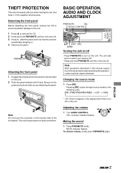
.... This could cause a poor or faulty connection. Pressing SRC cycles through source modes in the following order: FM1 (FM2/FM3/AM1/AM2) → CD* → AUX ↑ * "CD" does not appear in the display when there is no CD in the unit. MUTE indicator flashes. To restore volume, briefly press PWR...
.... This could cause a poor or faulty connection. Pressing SRC cycles through source modes in the following order: FM1 (FM2/FM3/AM1/AM2) → CD* → AUX ↑ * "CD" does not appear in the display when there is no CD in the unit. MUTE indicator flashes. To restore volume, briefly press PWR...
Operating Instructions
Page 6
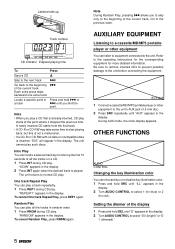
...appears. To cancel Random Play, press RNDM again. AUXILIARY EQUIPMENT Listening to a cassette/MD/MP3 portable player or other equipment to the unit. AUX jack 1 Connect a cassette/MD/MP3 portable player or other equipment You can locate a desired track by monitoring the first 10 seconds of ...in the display. One track Repeat Play You can choose blue or red as the key illumination color. 1 Press and hold SRC until "AUX" appears in the display. 2 Turn AUDIO CONTROL to the operating instructions for the corresponding equipment for red). OTHER FUNCTIONS AUDIO CONTROL Changing ...
...appears. To cancel Random Play, press RNDM again. AUXILIARY EQUIPMENT Listening to a cassette/MD/MP3 portable player or other equipment to the unit. AUX jack 1 Connect a cassette/MD/MP3 portable player or other equipment You can locate a desired track by monitoring the first 10 seconds of ...in the display. One track Repeat Play You can choose blue or red as the key illumination color. 1 Press and hold SRC until "AUX" appears in the display. 2 Turn AUDIO CONTROL to the operating instructions for the corresponding equipment for red). OTHER FUNCTIONS AUDIO CONTROL Changing ...
Operating Instructions
Page 7
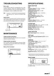
... the connector The connector needs to solve such problems. If the error code indication does not disappear, consult an AIWA service center. Power Output: 45 W × 4 channels AUX input Input sensitivity (load impedance) AUX: 300 mV (10 kΩ) GENERAL Power-Supply Voltage: 14.4 V (11 to 16 V allowable), DC, negative ground Load Impedance: 4 Ω...
... the connector The connector needs to solve such problems. If the error code indication does not disappear, consult an AIWA service center. Power Output: 45 W × 4 channels AUX input Input sensitivity (load impedance) AUX: 300 mV (10 kΩ) GENERAL Power-Supply Voltage: 14.4 V (11 to 16 V allowable), DC, negative ground Load Impedance: 4 Ω...
Service Manual
Page 2
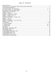
... BEAM DURING SERVICING 4 CAUTION WHEN SERVICING ...5 ELECTRICAL PARTS LIST (CDC-X227) ...6 ~ 10 ELECTRICAL PARTS LIST (CZA-4 SNYNF) ...11 ~ 13 ELECTRICAL PARTS LIST (BZG-3 BNF) ...14 TRANSISTOR ILLUSTRATION ...15 WIRING - 1 (MAIN) ...16 SCHEMATIC DIAGRAM - 1 (MAIN) ...17 WIRING - 2 (FRONT / AUX) ...18 WIRING - 2 (FRONT) ...19 SCHEMATIC DIAGRAM - 2 (FRONT / AUX) ...20 WIRING - 3 (CD) ...21 WIRING - 3 (......47 COLOR NAME TABLE ...48 CD MECHANISM EXPLODED VIEW ...49 CD MECHANISM PARTS LIST ...50 ACCESSORIES PARTS LIST ...51 OTHER PARTS LIST (CDC-X227) ...52 OTHER PARTS LIST (BZG-3 BNF) ...53 - 2 -
... BEAM DURING SERVICING 4 CAUTION WHEN SERVICING ...5 ELECTRICAL PARTS LIST (CDC-X227) ...6 ~ 10 ELECTRICAL PARTS LIST (CZA-4 SNYNF) ...11 ~ 13 ELECTRICAL PARTS LIST (BZG-3 BNF) ...14 TRANSISTOR ILLUSTRATION ...15 WIRING - 1 (MAIN) ...16 SCHEMATIC DIAGRAM - 1 (MAIN) ...17 WIRING - 2 (FRONT / AUX) ...18 WIRING - 2 (FRONT) ...19 SCHEMATIC DIAGRAM - 2 (FRONT / AUX) ...20 WIRING - 3 (CD) ...21 WIRING - 3 (......47 COLOR NAME TABLE ...48 CD MECHANISM EXPLODED VIEW ...49 CD MECHANISM PARTS LIST ...50 ACCESSORIES PARTS LIST ...51 OTHER PARTS LIST (CDC-X227) ...52 OTHER PARTS LIST (BZG-3 BNF) ...53 - 2 -
Service Manual
Page 3
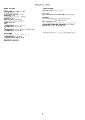
...: More than 85 dB Channel Separation: More than 60 dB S/N Ratio: More than 90 dB Wow/Flutter: Unmeasurable AUDIO SECTION Max. Power Output: 45 W x 4 channels AUX input Input Sensitivity (load impedance) AUX: 300 mV (10 kohms) GENERAL Power-Supply Voltage: 14.4 V (11 to change without notice. - 3 -
...: More than 85 dB Channel Separation: More than 60 dB S/N Ratio: More than 90 dB Wow/Flutter: Unmeasurable AUDIO SECTION Max. Power Output: 45 W x 4 channels AUX input Input Sensitivity (load impedance) AUX: 300 mV (10 kohms) GENERAL Power-Supply Voltage: 14.4 V (11 to change without notice. - 3 -
Service Manual
Page 4
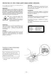
... BLOCK. ATTENTION L'utillisation de commandes, réglages ou procédures autres que ceux spécifiés peut entraîner une dangereuse exposition aux radiations. Be sure ground body and workbench, and use care the clothes do not touch the diode. 1) After the connection, remove solder shown in hazardous...
... BLOCK. ATTENTION L'utillisation de commandes, réglages ou procédures autres que ceux spécifiés peut entraîner une dangereuse exposition aux radiations. Be sure ground body and workbench, and use care the clothes do not touch the diode. 1) After the connection, remove solder shown in hazardous...
Service Manual
Page 6
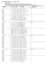
... 0712 87-A10-047-080 C-CAP,U 1-10 Z F O C 0731 87-A10-707-080 C-CAP,U 0.47-10 Z F O C 0732 87-A10-707-080 C-CAP,U 0.47-10 Z F SUFFIX&MODEL CDC-X227 YZSF a a a a a a a a a a FRONT FRONT FRONT FRONT FRONT FRONT FRONT FRONT FRONT FRONT O C 0735 87-012-278-080 C-CAP,U 2200P-50 K B GRM a O C 0736 87...a - 6 - Components marked S and O are designated as spare parts for service and will be stocked at the spare parts centers. UNIT-NAME AUX AUX FRONT FRONT FRONT FRONT FRONT FRONT FRONT FRONT ! Components marked X and R are shown in this service manual. However, please note that not all...
... 0712 87-A10-047-080 C-CAP,U 1-10 Z F O C 0731 87-A10-707-080 C-CAP,U 0.47-10 Z F O C 0732 87-A10-707-080 C-CAP,U 0.47-10 Z F SUFFIX&MODEL CDC-X227 YZSF a a a a a a a a a a FRONT FRONT FRONT FRONT FRONT FRONT FRONT FRONT FRONT FRONT O C 0735 87-012-278-080 C-CAP,U 2200P-50 K B GRM a O C 0736 87...a - 6 - Components marked S and O are designated as spare parts for service and will be stocked at the spare parts centers. UNIT-NAME AUX AUX FRONT FRONT FRONT FRONT FRONT FRONT FRONT FRONT ! Components marked X and R are shown in this service manual. However, please note that not all...

Service Manual
Page 18
WIRING - 2 (FRONT / AUX) 32 31 30 29 28 27 26 25 24 23 22 21 20 19 18 17 16 15 14 13 12 11 10 9 8 7 6 5 4 3 2 1 A B C D E F G H I J K L M N O P Q R S T U - 18 -
WIRING - 2 (FRONT / AUX) 32 31 30 29 28 27 26 25 24 23 22 21 20 19 18 17 16 15 14 13 12 11 10 9 8 7 6 5 4 3 2 1 A B C D E F G H I J K L M N O P Q R S T U - 18 -
Service Manual
Page 34
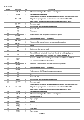
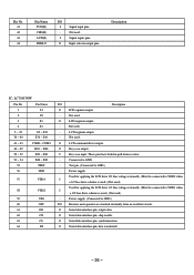
... OUT 24 LS3 25 NC 26 NC 27 LS IN 28 LT OUT 29 ~ 31 LT3 ~ LT1 32 L COM 33 LVR IN 34 LSELO 35 AUX(L) 36 CHG(L) 37 TUN(L) 38 CD(L) 39 VDD 40 CD(R) I/O Description I Super bass input. For the connection of capacitors that compensate for bass and treble...
... OUT 24 LS3 25 NC 26 NC 27 LS IN 28 LT OUT 29 ~ 31 LT3 ~ LT1 32 L COM 33 LVR IN 34 LSELO 35 AUX(L) 36 CHG(L) 37 TUN(L) 38 CD(L) 39 VDD 40 CD(R) I/O Description I Super bass input. For the connection of capacitors that compensate for bass and treble...
Service Manual
Page 35
... - synchronization. 64 DI O Serial data interface pin; output data. 62 CE O Serial data interface pin; Pin No. 41 42 43 44 Pin Name TUN(R) CHG(R) AUX(R) RSELO I/O I a 1/2 bias drive scheme is used.) (Not used) Used for applying the LCD drive 2/3 bias voltage externally. (Must be connected to VDD2 when 57 VDD1...
... - synchronization. 64 DI O Serial data interface pin; output data. 62 CE O Serial data interface pin; Pin No. 41 42 43 44 Pin Name TUN(R) CHG(R) AUX(R) RSELO I/O I a 1/2 bias drive scheme is used.) (Not used) Used for applying the LCD drive 2/3 bias voltage externally. (Must be connected to VDD2 when 57 VDD1...
Service Manual
Page 41
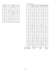
PIN NO. 70 71 72 73 74 75 76 77 78 79 80 CD TUNER AUX 0 2.51 0 0 0 0 0 0 0 4.88 4.89 4.88 0 0/2.34 0 0 2.45/0 0 0 0 0 0 0 0 0.97 0.97 1.02 0 0 0 2.49 2.46 2.47 TU101, FAE347-A31 PIN NO. ANT INPUT OPEN FM AM 1 0 0 2 0 0 3 0 0 4 7.82 0.2 5 0 0 6 3.42 3.42 7 0 0 8 0 0 9 0 8.7 ...
PIN NO. 70 71 72 73 74 75 76 77 78 79 80 CD TUNER AUX 0 2.51 0 0 0 0 0 0 0 4.88 4.89 4.88 0 0/2.34 0 0 2.45/0 0 0 0 0 0 0 0 0.97 0.97 1.02 0 0 0 2.49 2.46 2.47 TU101, FAE347-A31 PIN NO. ANT INPUT OPEN FM AM 1 0 0 2 0 0 3 0 0 4 7.82 0.2 5 0 0 6 3.42 3.42 7 0 0 8 0 0 9 0 8.7 ...

Service Manual
Page 47
...-010 CABI, OV 8C-KCG-015-010 BTN, OV B 8C-KCG-215-010 LENS, L 8C-KCG-014-010 BTN, OV R SUFFIX&MODEL CDC-X227 YZSF a a a a a a a a a a O MC1011 8C-KCG-013-010 BTN, OV OUT a O MC1012 8C-KCG-019-010...85-HRL-623-010 JACK,3.5 BLK ST BLK 8C-KCG-604-010 PWB,AUX 8Z-KC2-203-210 LEVER,DFP HOOK -C2 8Z-KC2-221-110 SPR-C,DETACH HOOK-C2 CDC-X227 YZSF a a a a a a a a a a O MC1031 ...AUX) a O MC1A 8Z-KC1-253-010 S-SCREW,PT 2*8 BH+ BLK a O MC1B 87-B10-384-010 UIT+2.6-6 a O MC1C 87-081-501-010 VTT+2.6-4 a O MC1D 87-B10-385-010 UIT+2.6-6 BLK a O MC1E O MC1F O MC1G O MC1H O MC1I O MC1J O MC1K CDC-X227...
...-010 CABI, OV 8C-KCG-015-010 BTN, OV B 8C-KCG-215-010 LENS, L 8C-KCG-014-010 BTN, OV R SUFFIX&MODEL CDC-X227 YZSF a a a a a a a a a a O MC1011 8C-KCG-013-010 BTN, OV OUT a O MC1012 8C-KCG-019-010...85-HRL-623-010 JACK,3.5 BLK ST BLK 8C-KCG-604-010 PWB,AUX 8Z-KC2-203-210 LEVER,DFP HOOK -C2 8Z-KC2-221-110 SPR-C,DETACH HOOK-C2 CDC-X227 YZSF a a a a a a a a a a O MC1031 ...AUX) a O MC1A 8Z-KC1-253-010 S-SCREW,PT 2*8 BH+ BLK a O MC1B 87-B10-384-010 UIT+2.6-6 a O MC1C 87-081-501-010 VTT+2.6-4 a O MC1D 87-B10-385-010 UIT+2.6-6 BLK a O MC1E O MC1F O MC1G O MC1H O MC1I O MC1J O MC1K CDC-X227...