AIWA CDC-R104 Support and Manuals
Get Help and Manuals for this AIWA item
View All Support Options Below
Free AIWA CDC-R104 manuals!
Problems with AIWA CDC-R104?
Ask a Question
Free AIWA CDC-R104 manuals!
Problems with AIWA CDC-R104?
Ask a Question
Most Recent AIWA CDC-R104 Questions

How To Set/change Clock Time
Unable to find clock/time settings from menu. Appreciate any help on how to set/change clock on the ...
Unable to find clock/time settings from menu. Appreciate any help on how to set/change clock on the ...
(Posted by jcatz 11 years ago)
AIWA CDC-R104 Videos

Aiwa CDC-R104+Hertz DCX-690+Hertz DCX-130 in BMW e36 Sedan
Duration: :54
Total Views: 3,195
Duration: :54
Total Views: 3,195
Popular AIWA CDC-R104 Manual Pages
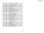
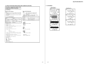
Service Manual - Page 2
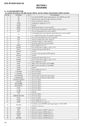
...laser OFF, H: laser ON)
2
PD
I Dimmer monitor input from optical pick-up laser diode.
3
PN
I CD reset signal input from system control IC. Analog power supply pin (+3.3 V)
5
DGND
- D/A converter power supply (+) pin ...
I Not used . (Connect to SCKIN in this set )
14 Capacitor connection pin for SCF regulator.
19
DAGND
- CDC-R104/X104/X144
SECTION 3 DIAGRAMS
3-1.
Service Manual - Page 3
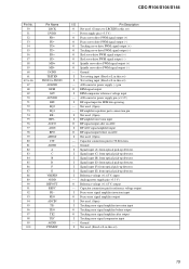
CDC-R104...RF signal output before on AGC. RF amplifier equalizer parts connection pin
I Not used . (Fixed at L in this set )
15 I Not used . (Open)
I ...error signal amplifier inversion input
O Tracking error signal amplifier before output
O Tracking error signal amplifier after on AGC. I Signal input (E) from optical pick-up detector. I Test setting input (Fixed at L in this set...
Service Manual - Page 4
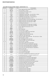
...output (32.768 kHz)
17
VDD2
- Pull up: "H"
19
RESET
I Reset signal input
20
NCO
O Not used in this set. (Open)
21
ACC IN
I Accessory power supply detection signal ...
- Ground pin for D/A output converter (+3.3 V)
2
BBE-MP
O Not used in this set . (Open)
3
DAVSS
- CDC-R104/X104/X144
• IC501 MN101E01KAB (SYSTEM CONTROL) (MAIN BOARD (1/2))
Pin No. Pin Name
I ...
Service Manual - Page 5
...to the LCD driver
O Chip enable signal output to the LCD driver
O Serial clock signal output to the LCD driver
I/O I2C BUS serial data signal input/output
O Not used in this set. (Open)...
O Not used in this set. (Open)
O Noise mask signal output
O Serial clock signal output for EEPROM communication
I/O Serial data signal input/output for A/D input converter
17
17
CDC-R104/X104/X144
Service Manual - Page 6
CDC-R104/X104/X144
3-2. DETECTOR PD1 PD1
PD2
PD2
82 A 84 B 83 C 85 D
RFO 78
77 AGCI AGCO 76
71 RFI...PICK-UP BLOCK
(KSS1000E)
2-AXIS DEVICE FCS+ FCS-
(FOCUS) (TRACKING)
TRK+ TRK- OPIN4+ 27 OPIN4- 26
M901 (SPINDLE)
M
17 VO3+ 18 VO3-
BLOCK DIAGRAM -
OPIN3+ 24 OPIN3- 23
M903 (LOADING)
M
10 VOL+ 9 VOL-
XTAL 23 XTAL 24
X1 16.934MHz
SW1 (DOWN)
SW2 (SELF)
SW3 (DISC IN)...
Service Manual - Page 7
...
REAR
R-CH
BATT
FU601
CN601 1 FL+ 9 FL- 2 RL+ 10 RL- 4 FR+ 12 3 FR- BLOCK DIAGRAM - RR+ 11 RR- 5 6 AMP-REM ANT-REM
16 BATT
BATT
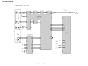
16 BEEP 22 STB 25 DIAG
35 VP
AUDIO...33 PANEL+B 34
AUDIO+8.3V BACK UP+3.3V SERVO+3.3V MECHA+6V PANEL+10V
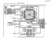
R104/X104: AEP,UK MODEL
ACC CHECK Q631
TEL ATT Q651
7 ACC
13 ATT
15 TEST
92 QUALITY... FM : AM/MW/LW
: AUX
19
19 MAIN SECTION - CDC-R104/X104/X144
3-3.
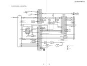
Service Manual - Page 8
...920
BACK UP+3.3V
RESET IC602
2 IN OUT 1
SYSTEM CONTROL IC501 (3/3)
98 RE
97 KEYIN2 27 KEYACK
LCD SO 76 LCD CKO 78
LCD CE 77
94 KEYIN1
95 KEYIN0
75 COL SEL 90 COL SW
LCD DRIVER IC901
64 DI 63...
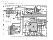
( ) LCD BACK LIGHT
PANEL+10V
LED DRIVE Q902,903
LED901-920
S702 RESET
19 RESET
X502 32.768kHz
15 XIN 16 XOUT
OSCIN 13 OSCOUT 12
X501 27MHz
3-5. CDC-R104/X104/X144
3-4. DISPLAY SECTION -
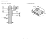
Service Manual - Page 9
... AUX
• Abbreviation
CND : Canadian model. For printed wiring boards. NOTE FOR PRINTED WIRING BOARDS AND SCHEMATIC DIAGRAMS
THIS NOTE IS COMMON FOR PRINTED WIRING BOARDS AND SCHEMATIC DIAGRAMS. (In addition to measure
• Voltages.... 200mVp-p
IC1 oh (TEO)
CDC-R104/X104/X144
- Replace only with a VOM (Input impedance 10 MΩ). Voltage variations may be noted due to normal ...
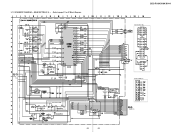
Service Manual - Page 10
CD MECHANISM SECTION - • Refer to page 21 for IC Block Diagram. SCHEMATIC DIAGRAM -
CN2
TP31
R13 C36
TP30
TP29
TP14 R12
C35
TP28 TP27
TP26
C34 R11
SW4
M901 ...TP72
C79 R85 R84 C78 R83 R82 C77 R81 R80 C76 R79 R78
TP75 TP74
C75
23
23
C19 JR90 JR91
CDC-R104/X104/X144
TP65
TP64
TP63
TP62
TP61
TP60
R45
TP59
R44
TP58
TP57
TP56
TP55
TP54
TP48
TP52
TP51
TP53
...
Service Manual - Page 11
... SECTION (1/2) - • Refer to page 21 for IC Block Diagrams.
TU1
J1
C3 C1 C2
R5
R4
C4 R1
C6
D1 Q1
C5
R15 R16 C9
IC B/D
R8 R10
R9
R6 R7
Q3
L1
IC51 ...
R521 R522
R510
R514
R513
R512 R541
C501
C510 R501
R502 R596
C511
R504
R595
R503
R565 C513
R505 R566
R543
(Page 25)
24
24 CDC-R104/X104/X144
• Refer to page 29 for Waveforms. 3-10.
Service Manual - Page 12
3-11. MAIN SECTION (2/2) - • Refer to page 31 for IC Block Diagram.
(Page 24)
C441 R441 R442
Q441
C461 R461
R462
C431 R431
R432
C451 R451
R452
C481 R481
R482
Q461 Q431 Q451 Q481
C471
R471
R472
...
R582 R583
D703 D702
R701
R731
R732
R735
C732 R734
C731 R733
L373
L374 L372 L731
D731 CN701
D711
D712
C704
(Page 28)
25
25
CDC-R104/X104/X144 SCHEMATIC DIAGRAM -
Service Manual - Page 17
Replace only with mark 0 are critical for safety. Ne les remplacer que par une piéce portant le numéro spécifié. No.
151 152 0 153 154 155
156
Part No....-850-77 SCREW, PRECISION +P 1.4X1.8
Remark
35 No.
157 158 M902 SW4 #5
Part No.
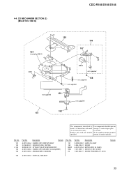
CD MECHANISM SECTION (2) (MG-611XC-186//Q)
CDC-R104/X104/X144
154
(including M901)
SW4
155 156
157
M902
#5 not supplied
158
not ...
Service Manual - Page 18
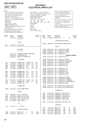
...the diagrams or the components used on the set. • -XX and -X mean standardized parts, so they are critical for example: uA.. : µA.. uPC.. : µPC..
Part No...model
The components identified by reference number, please include the board. No. CDC-R104/X104/X144
AUX KEY
NOTE: • Due to standardization, replacements in
the parts list may have some difference from the parts...
Service Manual - Page 19
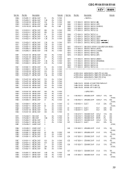
... METAL CHIP 3.3K R996 1-216-827-11 METAL CHIP 3.3K
CDC-R104/X104/X144 KEY MAIN
Remark Ref. Ref. Description
Remark
5% 1/10W...R104)
C54 1-107-826-11 CERAMIC CHIP 0.1uF 10% 16V (R104)
C55 1-107-826-11 CERAMIC CHIP 0.1uF 10% 16V (R104)
C56 1-107-826-11 CERAMIC CHIP 0.1uF 10% 16V (R104)
C57 1-107-826-11 CERAMIC CHIP 0.1uF 10% 16V (R104)
C58 1-107-826-11 CERAMIC CHIP 0.1uF 10% 16V (R104)
39 Part...
Service Manual - Page 24
...
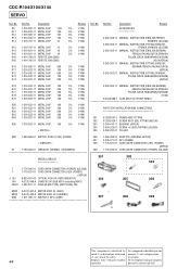
R85 1-216-833-11 METAL CHIP 10K
< SWITCH >
5% 1/10W
3-263-364-11 MANUAL, INSTRUCTION (ENGLISH,GERMAN,
5% 1/10W
FRENCH,ITALIAN,DUTCH,SPANISH,
5% 1/10W
POLISH,CZECH,HUNGARIAN,RUSSIAN)
5% 1/10W
(R104)
5% 1/10W
X-3384-688-1 CASE ASSY (for FRONT PANEL)
5% 1/10W
5% 1/10W
PARTS FOR INSTALLATION AND CONNECTIONS
5% 1/10W
5% 1/10W
5% 1/10W
301 X-3382-647-1 FRAME ASSY, FITTING
302...
AIWA CDC-R104 Reviews
We have not received any reviews for AIWA yet.