
Operating Instructions
Page 1
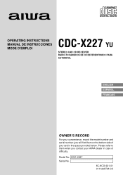
CDC-X227 Serial No. 8C-KCG-921-01 011120ATM-OX OPERATING INSTRUCTIONS MANUAL DE INSTRUCCIONES MODE D'EMPLOI CDC-X227 YU STEREO CAR CD RECEIVER RADIO-TOCADISCOS DE CD ESTEREOFONICO PARA AUTOMOVIL ENGLISH ESPAÑOL FRANÇAIS OWNER'S RECORD For your convenience, record the model number and serial number (you contact your set) in case of your AIWA dealer in the space provided below. Model No. Please refer to them when you will find them on the bottom side of difficulty.
CDC-X227 Serial No. 8C-KCG-921-01 011120ATM-OX OPERATING INSTRUCTIONS MANUAL DE INSTRUCCIONES MODE D'EMPLOI CDC-X227 YU STEREO CAR CD RECEIVER RADIO-TOCADISCOS DE CD ESTEREOFONICO PARA AUTOMOVIL ENGLISH ESPAÑOL FRANÇAIS OWNER'S RECORD For your convenience, record the model number and serial number (you contact your set) in case of your AIWA dealer in the space provided below. Model No. Please refer to them when you will find them on the bottom side of difficulty.
Operating Instructions
Page 2
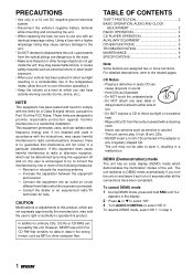
... harmful interference in sound. • Hold CDs as benzine or alcohol. • This unit cannot play 3-inch (8 cm) CDs. • NEVER insert a 3-inch CD contained in the adapter or any seal, label or data protection sheet to either side of the unit. TABLE OF CONTENTS THEFT PROTECTION 2 BASIC OPERATION, AUDIO AND CLOCK ADJUSTMENT 2 RADIO OPERATION 3 CD PLAYER OPERATION 4 AUXILIARY EQUIPMENT 5 OTHER FUNCTIONS 5 TROUBLESHOOTING 6 MAINTENANCE 6 SPECIFICATIONS 6 Note Some buttons are not...
... harmful interference in sound. • Hold CDs as benzine or alcohol. • This unit cannot play 3-inch (8 cm) CDs. • NEVER insert a 3-inch CD contained in the adapter or any seal, label or data protection sheet to either side of the unit. TABLE OF CONTENTS THEFT PROTECTION 2 BASIC OPERATION, AUDIO AND CLOCK ADJUSTMENT 2 RADIO OPERATION 3 CD PLAYER OPERATION 4 AUXILIARY EQUIPMENT 5 OTHER FUNCTIONS 5 TROUBLESHOOTING 6 MAINTENANCE 6 SPECIFICATIONS 6 Note Some buttons are not...
Operating Instructions
Page 3
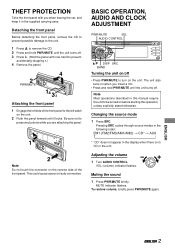
... attaching the panel. Changing the source mode 1 Press SRC. THEFT PROTECTION Take the front panel with one hand to the left catch on the reverse side of the front panel. BASIC OPERATION, AUDIO AND CLOCK ADJUSTMENT PWR/MUTE SEL AUDIO CONTROL i/k DISP SRC BAND Turning the unit on/off • Press PWR/MUTE to press any buttons while you when leaving the car, and keep it .) 4 Remove the panel. ENGLISH ENGLISH...
... attaching the panel. Changing the source mode 1 Press SRC. THEFT PROTECTION Take the front panel with one hand to the left catch on the reverse side of the front panel. BASIC OPERATION, AUDIO AND CLOCK ADJUSTMENT PWR/MUTE SEL AUDIO CONTROL i/k DISP SRC BAND Turning the unit on/off • Press PWR/MUTE to press any buttons while you when leaving the car, and keep it .) 4 Remove the panel. ENGLISH ENGLISH...
Operating Instructions
Page 4
... selected mode's indicator flashes. 2 Turn AUDIO CONTROL to increase/decrease the level or to search for the selected mode. Muting button beep sounds 1 Turn off for a desired station while increasing or decreasing the frequency step by step (Manual Tuning). Note Adjust the level or select on /off the unit. 2 Press and hold DISP until "bEEP" appears in the display. Restoring the factory settings 1 Turn off the unit. 2 Press and hold SEL until "LA --" appears in the display. 3 Turn AUDIO CONTROL...
... selected mode's indicator flashes. 2 Turn AUDIO CONTROL to increase/decrease the level or to search for the selected mode. Muting button beep sounds 1 Turn off for a desired station while increasing or decreasing the frequency step by step (Manual Tuning). Note Adjust the level or select on /off the unit. 2 Press and hold DISP until "bEEP" appears in the display. Restoring the factory settings 1 Turn off the unit. 2 Press and hold SEL until "LA --" appears in the display. 3 Turn AUDIO CONTROL...
Operating Instructions
Page 5
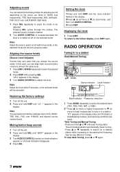
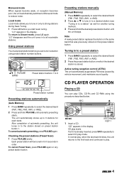
... a CD. "CD" appears in order. i/k PS/A.ME BAND Preset station buttons 1 to 6 Preset station number Presetting stations automatically (Auto Memory) 1 Press BAND repeatedly to select CD play starts. Active tuning reception control (ATRC) The unit automatically suppresses FM noise caused by vehicle movement, and maintains sound quality. ENGLISH 4 To cancel Preset Scan, press PS/A.ME again or any preset station button. "LO" appears in the display. To return to reduce noise. CD play mode.
... a CD. "CD" appears in order. i/k PS/A.ME BAND Preset station buttons 1 to 6 Preset station number Presetting stations automatically (Auto Memory) 1 Press BAND repeatedly to select CD play starts. Active tuning reception control (ATRC) The unit automatically suppresses FM noise caused by vehicle movement, and maintains sound quality. ENGLISH 4 To cancel Preset Scan, press PS/A.ME again or any preset station button. "LO" appears in the display. To return to reduce noise. CD play mode.
Operating Instructions
Page 6
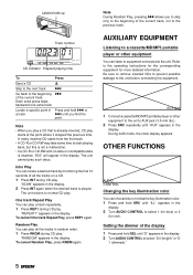
... equipment to the unit's AUX jack (3.5 mm dia.). 2 Press SRC repeatedly until "ILL" appears in the display. 2 Turn AUDIO CONTROL to select 1 (for blue) or 2 (for more detailed information. "RANDOM" appears in the display. AUX jack 1 Connect a cassette/MD/MP3 portable player or other equipment You can listen to equipment connected to normal CD play . OTHER FUNCTIONS AUDIO CONTROL Changing the key illumination color You can play all the tracks...
... equipment to the unit's AUX jack (3.5 mm dia.). 2 Press SRC repeatedly until "ILL" appears in the display. 2 Turn AUDIO CONTROL to select 1 (for blue) or 2 (for more detailed information. "RANDOM" appears in the display. AUX jack 1 Connect a cassette/MD/MP3 portable player or other equipment You can listen to equipment connected to normal CD play . OTHER FUNCTIONS AUDIO CONTROL Changing the key illumination color You can play all the tracks...
Operating Instructions
Page 7
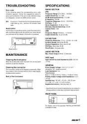
... than 85 dB Channel Separation: More than 60 dB S/N Ratio: More than 90 dB Wow/Flutter: Unmeasurable AUDIO SECTION Max. REAR PANEL For details, refer to solve such problems. If the error code indication does not disappear, consult an AIWA service center. Note that the CD is pressed. Wipe the surface of the front panel SPECIFICATIONS RADIO SECTION (FM) Frequency Range: 87.5 MHz...
... than 85 dB Channel Separation: More than 60 dB S/N Ratio: More than 90 dB Wow/Flutter: Unmeasurable AUDIO SECTION Max. REAR PANEL For details, refer to solve such problems. If the error code indication does not disappear, consult an AIWA service center. Note that the CD is pressed. Wipe the surface of the front panel SPECIFICATIONS RADIO SECTION (FM) Frequency Range: 87.5 MHz...
Service Manual
Page 2
TABLE OF CONTENTS SPECIFICATIONS ...3 PROTECTION OF EYES FROM LASER BEAM DURING SERVICING 4 CAUTION WHEN SERVICING ...5 ELECTRICAL PARTS LIST (CDC-X227) ...6 ~ 10 ELECTRICAL PARTS LIST (CZA-4 SNYNF) ...11 ~ 13 ELECTRICAL PARTS LIST (BZG-3 BNF) ...14 TRANSISTOR ILLUSTRATION ...15 WIRING - 1 (MAIN) ...16 SCHEMATIC DIAGRAM - 1 (MAIN) ...17 WIRING - 2 (FRONT / AUX) ...18 WIRING - 2 (FRONT) ...19 SCHEMATIC DIAGRAM - 2 (FRONT / AUX) ...20 WIRING - 3 (CD) ...21 WIRING - 3 (CD) ...22 SCHEMATIC DIAGRAM - 3 (CD / FLEX / SW) ...23 WIRING - 4 (FLEX / SW) ...24 LCD DIAGRAM ...25...
TABLE OF CONTENTS SPECIFICATIONS ...3 PROTECTION OF EYES FROM LASER BEAM DURING SERVICING 4 CAUTION WHEN SERVICING ...5 ELECTRICAL PARTS LIST (CDC-X227) ...6 ~ 10 ELECTRICAL PARTS LIST (CZA-4 SNYNF) ...11 ~ 13 ELECTRICAL PARTS LIST (BZG-3 BNF) ...14 TRANSISTOR ILLUSTRATION ...15 WIRING - 1 (MAIN) ...16 SCHEMATIC DIAGRAM - 1 (MAIN) ...17 WIRING - 2 (FRONT / AUX) ...18 WIRING - 2 (FRONT) ...19 SCHEMATIC DIAGRAM - 2 (FRONT / AUX) ...20 WIRING - 3 (CD) ...21 WIRING - 3 (CD) ...22 SCHEMATIC DIAGRAM - 3 (CD / FLEX / SW) ...23 WIRING - 4 (FLEX / SW) ...24 LCD DIAGRAM ...25...
Service Manual
Page 4
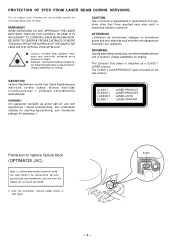
...Compact Disc player is located on the rear exterior. Therefore, be sure to replace Optical block (OPTIMA720 JVC) Body or clothes electrostatic potential could ruin laser diode in the optical block. CAUTION Use of controls or adjustments... use care the clothes do not touch the diode. 1) After the connection, remove ...servicing. Solder - 4 - ATTENTION L'utillisation de commandes, réglages ou procédures autres que ceux spécifiés peut entraîner une dangereuse exposition aux... WARNING!! PROTECTION OF EYES FROM LASER BEAM DURING SERVICING This set employs laser....
...Compact Disc player is located on the rear exterior. Therefore, be sure to replace Optical block (OPTIMA720 JVC) Body or clothes electrostatic potential could ruin laser diode in the optical block. CAUTION Use of controls or adjustments... use care the clothes do not touch the diode. 1) After the connection, remove ...servicing. Solder - 4 - ATTENTION L'utillisation de commandes, réglages ou procédures autres que ceux spécifiés peut entraîner une dangereuse exposition aux... WARNING!! PROTECTION OF EYES FROM LASER BEAM DURING SERVICING This set employs laser....
Service Manual
Page 8
...service manual. ! = ! UNIT-NAME MAIN MAIN MAIN MAIN MAIN MAIN MAIN MAIN MAIN MAIN ! Components marked X and R are not designated as spare parts for service and will be stocked at the production line are designated as spare parts for after sales service, and will be stocked at the spare parts centers. C REF-NO PARTS-NO PARTS...parts for after -sales service. SAFETY PARTS C = Components marked All components used on this model at the spare parts centers. S F 0251 8B-KC1-621-010 FUSE,15A 32V O FFC0701 8C-KCG-661-010 FF-CABLE...-A61-225-110 JACK,PIN 2P XR-401 CDC-X227 YZSF a a a ...
...service manual. ! = ! UNIT-NAME MAIN MAIN MAIN MAIN MAIN MAIN MAIN MAIN MAIN MAIN ! Components marked X and R are not designated as spare parts for service and will be stocked at the production line are designated as spare parts for after sales service, and will be stocked at the spare parts centers. C REF-NO PARTS-NO PARTS...parts for after -sales service. SAFETY PARTS C = Components marked All components used on this model at the spare parts centers. S F 0251 8B-KC1-621-010 FUSE,15A 32V O FFC0701 8C-KCG-661-010 FF-CABLE...-A61-225-110 JACK,PIN 2P XR-401 CDC-X227 YZSF a a a ...
Service Manual
Page 10
...-615-010 WIRE,400 P-MUTE O X 0901 87-A70-362-080 VIB,XTAL 4.5MHZ HC-49/U-S CDC-X227 YZSF a a a a - 10 - Components marked S and O are designated as spare parts for after sales service, and will not be stocked at the spare parts centers. SAFETY PARTS C = Components marked All components used on this service manual. Components marked X and R are shown in this model at the...
...-615-010 WIRE,400 P-MUTE O X 0901 87-A70-362-080 VIB,XTAL 4.5MHZ HC-49/U-S CDC-X227 YZSF a a a a - 10 - Components marked S and O are designated as spare parts for after sales service, and will not be stocked at the spare parts centers. SAFETY PARTS C = Components marked All components used on this service manual. Components marked X and R are shown in this model at the...
Service Manual
Page 28
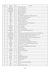
... power switch output. LM- Normal set to "H". 38 LP UP O RW disc control. Pin Name I/O Description 1 XIN I Input data signal for volume level control. 21 ACC-CONT O Output CD changer ACC signal. (Not used) 22 KS4 O Initial setting diode matrix output. (Not used) 23 KS3 O Initial setting diode matrix output. (Not used) 24 KS2 O Initial setting diode matrix output. (Not used ) 19 NC - O Thread motor control terminal. 37 RW O RW disc control. Not used ) 4 NC - Stereo signal input when receiving...
... power switch output. LM- Normal set to "H". 38 LP UP O RW disc control. Pin Name I/O Description 1 XIN I Input data signal for volume level control. 21 ACC-CONT O Output CD changer ACC signal. (Not used) 22 KS4 O Initial setting diode matrix output. (Not used) 23 KS3 O Initial setting diode matrix output. (Not used) 24 KS2 O Initial setting diode matrix output. (Not used ) 19 NC - O Thread motor control terminal. 37 RW O RW disc control. Not used ) 4 NC - Stereo signal input when receiving...
Service Manual
Page 29
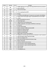
... cm disc ejection and detection. LCD driver data signal input. Not used . "Detect RF" RF level detection input. Leading motor start detection. System clock oscillator output. - 29 - ST-BY mute signal output. BEEP output (3kHz, 50ms). Read/write control output terminal. Rotary encoder input 2. External mute control. "L"= -20dB mute. AM channel transmission input. MUTE I RESET I ACC IN I SNS I BATT IN I IF (FM/AM) I VSS - Power mute signal output. Pulled down when not used . Not used . Sub-code Q output standby input terminal...
... cm disc ejection and detection. LCD driver data signal input. Not used . "Detect RF" RF level detection input. Leading motor start detection. System clock oscillator output. - 29 - ST-BY mute signal output. BEEP output (3kHz, 50ms). Read/write control output terminal. Rotary encoder input 2. External mute control. "L"= -20dB mute. AM channel transmission input. MUTE I RESET I ACC IN I SNS I BATT IN I IF (FM/AM) I VSS - Power mute signal output. Pulled down when not used . Not used . Sub-code Q output standby input terminal...
Service Manual
Page 31
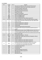
... 59 60 61 62 63 64 Pin Name HFL SLOF CVCV+ RFSM RFS- For the connection of a capacitor to control the DSP's data slice level of servo and digital circuits. - O Output for disc defect detection. - Set the time constant for the focus search smoothing capacitor. I Microprocessor command data input. I /O Description The HFL (high frequency level) signal is positioned on O the pit...
... 59 60 61 62 63 64 Pin Name HFL SLOF CVCV+ RFSM RFS- For the connection of a capacitor to control the DSP's data slice level of servo and digital circuits. - O Output for disc defect detection. - Set the time constant for the focus search smoothing capacitor. I Microprocessor command data input. I /O Description The HFL (high frequency level) signal is positioned on O the pit...
Service Manual
Page 32
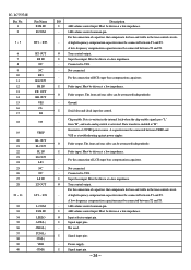
... output is a Schmitt input. O EFM data playback clock monitor. Internal VCO power supply. Can be set to 0V.) - I Tracking error signal input. I Track detection signal input. Digital system power supply. A pull-down resistor is locked. (Not used ) - Left channel ground. (Must be connected to 0V.) I Test input. Output 4.3218 MHz when the phase is built-in . (Must be connected to 0V.) O Right channel output. - I/O General purpose input/ output pin 1 ~ 5. (Not used ) I "H": Control...
... output is a Schmitt input. O EFM data playback clock monitor. Internal VCO power supply. Can be set to 0V.) - I Tracking error signal input. I Track detection signal input. Digital system power supply. A pull-down resistor is locked. (Not used ) - Left channel ground. (Must be connected to 0V.) I Test input. Output 4.3218 MHz when the phase is built-in . (Must be connected to 0V.) O Right channel output. - I/O General purpose input/ output pin 1 ~ 5. (Not used ) I "H": Control...
Service Manual
Page 34
... and rear sides can be driven at a low impedance. - O Input selector output pin. A high-frequency compensation capacitors must be connected between VREF and VSS as a troubleshooting against power ripples. Must be attenuated independently. Not used. Power supply. O Tone control output. from "H", and each analog switch is activated. I Serial data and clock input for control. I Signal input pin. - 34 - A low-frequency compensation capacitors must be connected between T2 and T3. - 1dB volume control common pin...
... and rear sides can be driven at a low impedance. - O Input selector output pin. A high-frequency compensation capacitors must be connected between VREF and VSS as a troubleshooting against power ripples. Must be attenuated independently. Not used. Power supply. O Tone control output. from "H", and each analog switch is activated. I Serial data and clock input for control. I Signal input pin. - 34 - A low-frequency compensation capacitors must be connected between T2 and T3. - 1dB volume control common pin...
Service Manual
Page 45
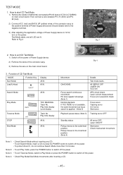
.... All lit. Note 2: • To exit Play mode, press the POWER button to switch off the power of Power Supply device. 2) Remove the wires of IC701 (LC72358N) on the power. Note 4: • Check Play Mode/Sled Mode movements after inserting a CD. - 45 - Test Mode starts, and all LCD are lit. Play Mode Traverse Mode STOP Sled Mode TOC READING Track No, Play time display Level display Track No, Play time display All lit. Note 1: • Check Search...
.... All lit. Note 2: • To exit Play mode, press the POWER button to switch off the power of Power Supply device. 2) Remove the wires of IC701 (LC72358N) on the power. Note 4: • Check Play Mode/Sled Mode movements after inserting a CD. - 45 - Test Mode starts, and all LCD are lit. Play Mode Traverse Mode STOP Sled Mode TOC READING Track No, Play time display Level display Track No, Play time display All lit. Note 1: • Check Search...

Service Manual
Page 47
... 16 CDC-X227 YZSF a a a a a a a a a a O MC1051 8A-KT1-645-010 CONN ASSY,8P ISO-BLACK-B a X MC1052 8C-KCG-254-010 HLDR,ISO-WIRE a X MC1053 8C-KCG-255-010 TUBE,ISO WIRE D12 a X MC1054 8A-KCG-615-010 WIRE,400 P-MUTE a O MC1055 8A-KT1-646-010 CONN ASSY,8P ISO-WHITE-B a O MC1056 8A-KC7-611-010 F-CABLE,3P (AUX) a O MC1A...
... 16 CDC-X227 YZSF a a a a a a a a a a O MC1051 8A-KT1-645-010 CONN ASSY,8P ISO-BLACK-B a X MC1052 8C-KCG-254-010 HLDR,ISO-WIRE a X MC1053 8C-KCG-255-010 TUBE,ISO WIRE D12 a X MC1054 8A-KCG-615-010 WIRE,400 P-MUTE a O MC1055 8A-KT1-646-010 CONN ASSY,8P ISO-WHITE-B a O MC1056 8A-KC7-611-010 F-CABLE,3P (AUX) a O MC1A...
Service Manual
Page 50
...parts for after sales service, and will be stocked at the spare parts centers. Components marked S and O are designated as spare parts for after -sales service. Components marked X and R are shown in this service manual. C REF-NO PARTS-NO PARTS...MODEL BZG-3 BNF a a a a a a a a a a O SC1011 8B-ZG3-241-110 SHAFT,ROLLER a O SC1012 8B-ZG3-252-010 SPR-T,ROLLER a O SC1013 8B-ZG3-231-010 TURN...MODE CH X SC1020a 8B-ZG3-210-110 LEVER,MODE...-221-010 GEAR,CONNECT a O SC1023 8B...SUPPORT A X SC1049c 8B-ZG3-292-210 SHAFT,SUPPORT B X SC1050 8B-ZG3-602-010 PWB,SUB 35M X SC1051 8B-ZG3-605-010 WIRE...
...parts for after sales service, and will be stocked at the spare parts centers. Components marked S and O are designated as spare parts for after -sales service. Components marked X and R are shown in this service manual. C REF-NO PARTS-NO PARTS...MODEL BZG-3 BNF a a a a a a a a a a O SC1011 8B-ZG3-241-110 SHAFT,ROLLER a O SC1012 8B-ZG3-252-010 SPR-T,ROLLER a O SC1013 8B-ZG3-231-010 TURN...MODE CH X SC1020a 8B-ZG3-210-110 LEVER,MODE...-221-010 GEAR,CONNECT a O SC1023 8B...SUPPORT A X SC1049c 8B-ZG3-292-210 SHAFT,SUPPORT B X SC1050 8B-ZG3-602-010 PWB,SUB 35M X SC1051 8B-ZG3-605-010 WIRE...
Service Manual
Page 52
...parts for after sales service, and will be stocked at the spare parts centers. Components marked X and R are not designated as spare parts for after -sales service. SAFETY PARTS C = Components marked All components used on this service manual. UNIT...8C-KCF-852-010 CUSHION,RIGHT AIS SUFFIX&MODEL CDC-X227 YZSF a a a a a a ...CODE A 35X8 a X 87-B40-154-010 LBL,BAR-CODE CU a X 8Z-HC4-028-010 LBL,CLASS 1 & TRIANGLE-G a X 8C-KCG-046-010 LBL,SPEC.YZ X227 X 8C-KCG-223-010 SH,5-10-0.07 BLK X 8C-KCG-222-010 SH, 3-2-1 W/ADH CDC-X227 YZSF a a a - 52 - OTHERS PARTS LIST (CDC-X227...
...parts for after sales service, and will be stocked at the spare parts centers. Components marked X and R are not designated as spare parts for after -sales service. SAFETY PARTS C = Components marked All components used on this service manual. UNIT...8C-KCF-852-010 CUSHION,RIGHT AIS SUFFIX&MODEL CDC-X227 YZSF a a a a a a ...CODE A 35X8 a X 87-B40-154-010 LBL,BAR-CODE CU a X 8Z-HC4-028-010 LBL,CLASS 1 & TRIANGLE-G a X 8C-KCG-046-010 LBL,SPEC.YZ X227 X 8C-KCG-223-010 SH,5-10-0.07 BLK X 8C-KCG-222-010 SH, 3-2-1 W/ADH CDC-X227 YZSF a a a - 52 - OTHERS PARTS LIST (CDC-X227...


