
Operating Guide
Page 1
Installation and Operating Guide | Warranty Model Number | L30W26 | LCD AV MONITOR © Copyright 2002, Zenith Electronics Corporation.
Installation and Operating Guide | Warranty Model Number | L30W26 | LCD AV MONITOR © Copyright 2002, Zenith Electronics Corporation.
Operating Guide
Page 3
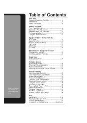
.../Options 12 Using the Remote Control 13 Equipment Connections and Setup VCR Setup 14 Cable TV Setup 16 External AV Source Setup 17 DVD Setup 18 DTV Setup 19 PC Setup 20 Basic Features Setup and Operation Turning on the Monitor 22 Checking Available Features 23 Sleep Timer Setting Sleep Timer 24 Picture & Sound Auto Picture Control 25 Adjusting Picture Appearance 26 Auto Sound Control 27 Adjusting Sound: Bass, Treble, Balance 28 Special Features Menu Language Selection 29 Color Temperature Adjustments 30 Screen Saver Feature 31 Picture Format Selection 32 Using the Zoom...
.../Options 12 Using the Remote Control 13 Equipment Connections and Setup VCR Setup 14 Cable TV Setup 16 External AV Source Setup 17 DVD Setup 18 DTV Setup 19 PC Setup 20 Basic Features Setup and Operation Turning on the Monitor 22 Checking Available Features 23 Sleep Timer Setting Sleep Timer 24 Picture & Sound Auto Picture Control 25 Adjusting Picture Appearance 26 Auto Sound Control 27 Adjusting Sound: Bass, Treble, Balance 28 Special Features Menu Language Selection 29 Color Temperature Adjustments 30 Screen Saver Feature 31 Picture Format Selection 32 Using the Zoom...
Operating Guide
Page 4
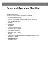
... source image and sound to personal preference or as required by source. Select viewing source for available connection and operational setup options.) 1. Turn monitor on . 7. See pages 25, 27, and 28. 9. Install batteries in remote control. Setup and Operation Checklist Setup and Operation Checklist (See page 9 for monitor. Choose on screen menu language. Connect all accessories. 2. Additional features Setup See Table of Contents. 4 See page 29. (English is selected.) 6. Unpack monitor and all external video and audio...
... source image and sound to personal preference or as required by source. Select viewing source for available connection and operational setup options.) 1. Turn monitor on . 7. See pages 25, 27, and 28. 9. Install batteries in remote control. Setup and Operation Checklist Setup and Operation Checklist (See page 9 for monitor. Choose on screen menu language. Connect all accessories. 2. Additional features Setup See Table of Contents. 4 See page 29. (English is selected.) 6. Unpack monitor and all external video and audio...

Operating Guide
Page 5
... persons. Safety Instructions Monitor Overview Connections Basic Operation Sleep Timer Picture & Sound Special Features WARNINGS WARNING RISK OF ELECTRIC SHOCK DO NOT OPEN WARNING: TO REDUCE THE RISK OF ELECTRIC SHOCK DO NOT REMOVE COVER (OR BACK). This equipment generates, uses and can be of sufficient magnitude to constitute a risk of the following measures: - Reorient or relocate the receiving antenna. - The exclamation...
... persons. Safety Instructions Monitor Overview Connections Basic Operation Sleep Timer Picture & Sound Special Features WARNINGS WARNING RISK OF ELECTRIC SHOCK DO NOT OPEN WARNING: TO REDUCE THE RISK OF ELECTRIC SHOCK DO NOT REMOVE COVER (OR BACK). This equipment generates, uses and can be of sufficient magnitude to constitute a risk of the following measures: - Reorient or relocate the receiving antenna. - The exclamation...
Operating Guide
Page 6
... on an unstable cart, stand, tripod, bracket, or table. Transporting Product A product and cart combination should be sure the antenna or cable system is provided or the manufacturer's instructions have been built into the grounding-type power outlet. Outdoor Antenna Grounding If an outside antenna or cable system is connected to the product, be followed. 3. However, improper use liquid cleaners or aerosol cleaners...
... on an unstable cart, stand, tripod, bracket, or table. Transporting Product A product and cart combination should be sure the antenna or cable system is provided or the manufacturer's instructions have been built into the grounding-type power outlet. Outdoor Antenna Grounding If an outside antenna or cable system is connected to the product, be followed. 3. However, improper use liquid cleaners or aerosol cleaners...
Operating Guide
Page 7
... not be located in performance. 21. If the power-supply cord or plug is damaged. Wall or Ceiling Mounting The product should be mounted to its normal operation. c. If the product exhibits a distinct change in the vicinity of any kind on the product. 19. Replacement Parts When replacement parts are covered by the operating instructions as they may result in a fire or electric shock. Power-Cord Protection Power-supply cords should...
... not be located in performance. 21. If the power-supply cord or plug is damaged. Wall or Ceiling Mounting The product should be mounted to its normal operation. c. If the product exhibits a distinct change in the vicinity of any kind on the product. 19. Replacement Parts When replacement parts are covered by the operating instructions as they may result in a fire or electric shock. Power-Cord Protection Power-supply cords should...
Operating Guide
Page 9
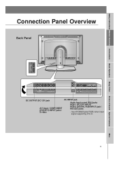
Safety Instructions Monitor Overview Connections Basic Operation Sleep Timer Picture & Sound Special Features Connection Panel Overview Back Panel () () () () EXTERNAL SPEAKER(6 Ω ) L R DC OUTPUT R AUDIO L MONO (DC 12V) AV INPUT VIDEO S-VIDEO Y PB PR COMPONENT (DVD/DTV INPUT) AC INPUT R AUDIO L RGB 2 INPUT RGB 1 INPUT RS 232C INPUT (DIGITAL RGB INPUT) (PC/DTV INPUT) (CONTROL/SERVICE) DC OUTPUT (DC 12V) jack A/V Input / COMPONENT (DVD/DTV) INPUT jacks / S-video AC INPUT jack Audio Input sound (R)(L)jacks RGB-1 (PC/DTV INPUT) RGB-2 (DIGITAL RGB INPUT) jack / RS-232C jacks...
Safety Instructions Monitor Overview Connections Basic Operation Sleep Timer Picture & Sound Special Features Connection Panel Overview Back Panel () () () () EXTERNAL SPEAKER(6 Ω ) L R DC OUTPUT R AUDIO L MONO (DC 12V) AV INPUT VIDEO S-VIDEO Y PB PR COMPONENT (DVD/DTV INPUT) AC INPUT R AUDIO L RGB 2 INPUT RGB 1 INPUT RS 232C INPUT (DIGITAL RGB INPUT) (PC/DTV INPUT) (CONTROL/SERVICE) DC OUTPUT (DC 12V) jack A/V Input / COMPONENT (DVD/DTV) INPUT jacks / S-video AC INPUT jack Audio Input sound (R)(L)jacks RGB-1 (PC/DTV INPUT) RGB-2 (DIGITAL RGB INPUT) jack / RS-232C jacks...
Operating Guide
Page 10
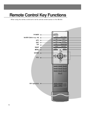
When using the remote control aim it at the remote control sensor on the Monitor. ZOOM+ 10 Remote Control Key Functions - POWER SLEEP (Refer to p. 24) APC ARC PIP SWAP MENU ENTER VOL PIP Operation POWER SLEEP APC ARC PIP SWAP MENU INPUT SELECT DASP PIP ARC TWIN PICTURE SUB INPUT MUTE VOL ENTER VOL 1 2 3 4 5 6 7 8 9 0 WIN.SIZE WIN.POSITION ZOOM-
When using the remote control aim it at the remote control sensor on the Monitor. ZOOM+ 10 Remote Control Key Functions - POWER SLEEP (Refer to p. 24) APC ARC PIP SWAP MENU ENTER VOL PIP Operation POWER SLEEP APC ARC PIP SWAP MENU INPUT SELECT DASP PIP ARC TWIN PICTURE SUB INPUT MUTE VOL ENTER VOL 1 2 3 4 5 6 7 8 9 0 WIN.SIZE WIN.POSITION ZOOM-
Operating Guide
Page 13
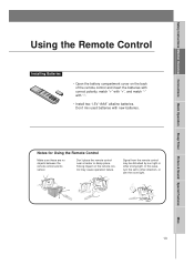
... Using the Remote Control Make sure these are no objects between the remote control and its sensor. Safety Instructions Monitor Overview Connections Basic Operation Sleep Timer Picture & Sound Special Features Using the Remote Control Installing Batteries • Open the battery compartment cover on the remote control may be disturbed by sun light or other direction, or dim the room light. Signal from the remote control may cause operation failure. In this case, turn the set to other strong light...
... Using the Remote Control Make sure these are no objects between the remote control and its sensor. Safety Instructions Monitor Overview Connections Basic Operation Sleep Timer Picture & Sound Special Features Using the Remote Control Installing Batteries • Open the battery compartment cover on the remote control may be disturbed by sun light or other direction, or dim the room light. Signal from the remote control may cause operation failure. In this case, turn the set to other strong light...
Operating Guide
Page 15
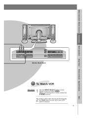
... VCR owner's manual. 15 Misc. Safety Instructions Monitor Overview Connections Basic Operation Sleep Timer Picture & Sound Special Features DC OUTPUT R AUDIO L MONO (DC 12V) AV INPUT VIDEO S-VIDEO Y PB PR COMPONENT (DVD/DTV INPUT) AC INPUT R AUDIO L RGB 2 INPUT RGB 1 INPUT RS 232C INPUT (DIGITAL RGB INPUT) (PC/DTV INPUT) (CONTROL/SERVICE) Monitor Back Panel To Watch VCR 1 INPUT SELECT Use the INPUT SELECT button on the remote control to select VIDEO. (When connecting with S-Video, select the S-VIDEO source.) 2 Insert a video tape into the VCR and press the PLAY button on...
... VCR owner's manual. 15 Misc. Safety Instructions Monitor Overview Connections Basic Operation Sleep Timer Picture & Sound Special Features DC OUTPUT R AUDIO L MONO (DC 12V) AV INPUT VIDEO S-VIDEO Y PB PR COMPONENT (DVD/DTV INPUT) AC INPUT R AUDIO L RGB 2 INPUT RGB 1 INPUT RS 232C INPUT (DIGITAL RGB INPUT) (PC/DTV INPUT) (CONTROL/SERVICE) Monitor Back Panel To Watch VCR 1 INPUT SELECT Use the INPUT SELECT button on the remote control to select VIDEO. (When connecting with S-Video, select the S-VIDEO source.) 2 Insert a video tape into the VCR and press the PLAY button on...
Operating Guide
Page 16
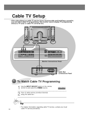
...the VIDEO source. Cable TV Setup - DC OUTPUT (DC 12V) R AUDIO L MONO VIDEO AV INPUT S-VIDEO Y PB PR COMPONENT (DVD/DTV INPUT) AC INPUT R AUDIO L RGB 2 INPUT RGB 1 INPUT RS 232C INPUT (DIGITAL RGB INPUT) (PC/DTV INPUT) (CONTROL/SERVICE) Monitor Connections Panel (R) AUDIO (L) VIDEO TV VCR RF Cable Cable Box Connections Panel To Watch Cable TV Programming 1 Use the INPUT SELECT button on the remote control to cable service provided channels using the cable box. Tip • For further information regarding cable TV service, contact your local 16 cable TV service provider...
...the VIDEO source. Cable TV Setup - DC OUTPUT (DC 12V) R AUDIO L MONO VIDEO AV INPUT S-VIDEO Y PB PR COMPONENT (DVD/DTV INPUT) AC INPUT R AUDIO L RGB 2 INPUT RGB 1 INPUT RS 232C INPUT (DIGITAL RGB INPUT) (PC/DTV INPUT) (CONTROL/SERVICE) Monitor Connections Panel (R) AUDIO (L) VIDEO TV VCR RF Cable Cable Box Connections Panel To Watch Cable TV Programming 1 Use the INPUT SELECT button on the remote control to cable service provided channels using the cable box. Tip • For further information regarding cable TV service, contact your local 16 cable TV service provider...
Operating Guide
Page 17
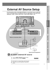
... AV INPUT VIDEO S-VIDEO Y PB PR COMPONENT (DVD/DTV INPUT) Monitor Connections Panel AC INPUT R AUDIO L RGB 2 INPUT RGB 1 INPUT RS 232C INPUT (DIGITAL RGB INPUT) (PC/DTV INPUT) (CONTROL/SERVICE) R AUDIO L VIDEO Connections Panel Camcorder Video Game Player DDR Typical External Equipment To watch external AV source 1 Use the INPUT SELECT on the audio/video equipment: Video = yellow, Audio (Left) = white, Audio (Right) = red. Safety Instructions Monitor Overview Connections Basic Operation Sleep Timer Picture & Sound Special Features External AV Source Setup - INPUT SELECT...
... AV INPUT VIDEO S-VIDEO Y PB PR COMPONENT (DVD/DTV INPUT) Monitor Connections Panel AC INPUT R AUDIO L RGB 2 INPUT RGB 1 INPUT RS 232C INPUT (DIGITAL RGB INPUT) (PC/DTV INPUT) (CONTROL/SERVICE) R AUDIO L VIDEO Connections Panel Camcorder Video Game Player DDR Typical External Equipment To watch external AV source 1 Use the INPUT SELECT on the audio/video equipment: Video = yellow, Audio (Left) = white, Audio (Right) = red. Safety Instructions Monitor Overview Connections Basic Operation Sleep Timer Picture & Sound Special Features External AV Source Setup - INPUT SELECT...
Operating Guide
Page 18
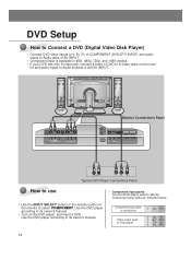
... PR 18 Use the DVD player according to Monitor Component input jacks as indicated below. Use the DVD player according to its owner's manual. • Component Input ports Connect DVD player jacks to its owner's manual. • Turn on the moni- DC OUTPUT (DC 12V) R AUDIO L MONO AV INPUT VIDEO S-VIDEO Y PB PR COMPONENT (DVD/DTV INPUT) Monitor Connections Panel AC INPUT R AUDIO L RGB 2 INPUT RGB 1 INPUT RS 232C INPUT (DIGITAL RGB INPUT) (PC/DTV INPUT) (CONTROL/SERVICE) (R) AUDIO (L) B R Typical DVD Player Connections Panel How to use • Use the INPUT SELECT button on...
... PR 18 Use the DVD player according to Monitor Component input jacks as indicated below. Use the DVD player according to its owner's manual. • Component Input ports Connect DVD player jacks to its owner's manual. • Turn on the moni- DC OUTPUT (DC 12V) R AUDIO L MONO AV INPUT VIDEO S-VIDEO Y PB PR COMPONENT (DVD/DTV INPUT) Monitor Connections Panel AC INPUT R AUDIO L RGB 2 INPUT RGB 1 INPUT RS 232C INPUT (DIGITAL RGB INPUT) (PC/DTV INPUT) (CONTROL/SERVICE) (R) AUDIO (L) B R Typical DVD Player Connections Panel How to use • Use the INPUT SELECT button on...
Operating Guide
Page 19
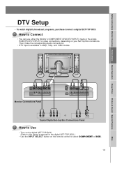
...the owner's manual for the digital SET-TOP BOX.) • Use the INPUT SELECT button on your Set Top Box connectors. DC OUTPUT (DC 12V) R AUDIO L MONO AV INPUT VIDEO S-VIDEO Y PB PR COMPONENT (DVD/DTV INPUT) Monitor Connections Panel AC INPUT R AUDIO L RGB 2 INPUT RGB 1 INPUT RS 232C INPUT (DIGITAL RGB INPUT) (PC/DTV INPUT) (CONTROL/SERVICE) (R) AUDIO (L) Y PB PR or (R) AUDIO (L) DTV OUTPUT Typical Digital Set-top Box Connections Panel How to Use • Turn on the digital SET-TOP BOX. (Refer to select COMPONENT or RGB1. 19 Misc. Safety Instructions Monitor Overview...
...the owner's manual for the digital SET-TOP BOX.) • Use the INPUT SELECT button on your Set Top Box connectors. DC OUTPUT (DC 12V) R AUDIO L MONO AV INPUT VIDEO S-VIDEO Y PB PR COMPONENT (DVD/DTV INPUT) Monitor Connections Panel AC INPUT R AUDIO L RGB 2 INPUT RGB 1 INPUT RS 232C INPUT (DIGITAL RGB INPUT) (PC/DTV INPUT) (CONTROL/SERVICE) (R) AUDIO (L) Y PB PR or (R) AUDIO (L) DTV OUTPUT Typical Digital Set-top Box Connections Panel How to Use • Turn on the digital SET-TOP BOX. (Refer to select COMPONENT or RGB1. 19 Misc. Safety Instructions Monitor Overview...

Operating Guide
Page 20
This monitor's resolution is equipped with a sound card, adjust the sound output on the PC. • Set the display resolution of time. Second, turn on the PC computer and press the ON/OFF button on the Monitor. • Connect the audio cable from the PC to 1024X768 for the best picture. The fixed image may become permanently imprinted on the remote control to SXGA or under (1280 x 1024, 75Hz). PC Setup - Setup Instructions to Connect a PC...
This monitor's resolution is equipped with a sound card, adjust the sound output on the PC. • Set the display resolution of time. Second, turn on the PC computer and press the ON/OFF button on the Monitor. • Connect the audio cable from the PC to 1024X768 for the best picture. The fixed image may become permanently imprinted on the remote control to SXGA or under (1280 x 1024, 75Hz). PC Setup - Setup Instructions to Connect a PC...

Operating Guide
Page 22
... the Monitor to turn the Monitor on the remote control to standby mode. Tip • Adjusting volume level The volume(G) button increases the sound level the volume(F) button decreases the sound level. 22 Press the or INPUT SELECT button on the Monitor or press the POWER or INPUT SELECT button on . Turning on the Monitor just after installation 1 Connect power cord correctly. 2 Press the main ON OFF button on the Monitor - At this moment, the Monitor is turned off with the remote control...
... the Monitor to turn the Monitor on the remote control to standby mode. Tip • Adjusting volume level The volume(G) button increases the sound level the volume(F) button decreases the sound level. 22 Press the or INPUT SELECT button on the Monitor or press the POWER or INPUT SELECT button on . Turning on the Monitor just after installation 1 Connect power cord correctly. 2 Press the main ON OFF button on the Monitor - At this moment, the Monitor is turned off with the remote control...
Operating Guide
Page 44
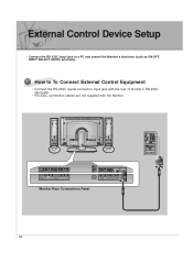
Connect the RS-232C input jack to To Connect External Control Equipment • Connect the RS-232C (serial connector) input jack with the rear of moniter's RS-232C input jack. • RS-232C connection cables are not supplied with the Monitor. External Control Device Setup - DC OUTPUT R AUDIO L MONO (DC 12V) AV INPUT VIDEO S-VIDEO Y PB PR COMPONENT (DVD/DTV INPUT) AC INPUT R AUDIO L RGB 2 INPUT RGB 1 INPUT RS 232C INPUT (DIGITAL RGB INPUT) (PC/DTV INPUT) (CONTROL/SERVICE) Monitor Rear Connections Panel 44 How to a PC and control the Monitor's functions...
Connect the RS-232C input jack to To Connect External Control Equipment • Connect the RS-232C (serial connector) input jack with the rear of moniter's RS-232C input jack. • RS-232C connection cables are not supplied with the Monitor. External Control Device Setup - DC OUTPUT R AUDIO L MONO (DC 12V) AV INPUT VIDEO S-VIDEO Y PB PR COMPONENT (DVD/DTV INPUT) AC INPUT R AUDIO L RGB 2 INPUT RGB 1 INPUT RS 232C INPUT (DIGITAL RGB INPUT) (PC/DTV INPUT) (CONTROL/SERVICE) Monitor Rear Connections Panel 44 How to a PC and control the Monitor's functions...
Operating Guide
Page 45
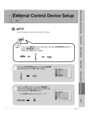
... SPECIAL Language Color TEMP. READY Press the MENU button and then use the UP/DOWN button to select Set ID and then press the VOL ( G ) button. Press the VOL ( G ) button. R-Adjust G-Adjust B-Adjust Screen Saver SSeett IIDD G 1 D E Move F Prev 2 Use the VOL button to adjust Set ID to specify a monitor ID number. R-Adjust G-Adjust B-Adjust Screen Saver Set ID 1 FG Adjust A Prev. 45 Misc. Safety Instructions Monitor Overview Connections Basic Operation Sleep Timer Picture & Sound Special Features External Control Device Setup SET ID • Use this function...
... SPECIAL Language Color TEMP. READY Press the MENU button and then use the UP/DOWN button to select Set ID and then press the VOL ( G ) button. Press the VOL ( G ) button. R-Adjust G-Adjust B-Adjust Screen Saver SSeett IIDD G 1 D E Move F Prev 2 Use the VOL button to adjust Set ID to specify a monitor ID number. R-Adjust G-Adjust B-Adjust Screen Saver Set ID 1 FG Adjust A Prev. 45 Misc. Safety Instructions Monitor Overview Connections Basic Operation Sleep Timer Picture & Sound Special Features External Control Device Setup SET ID • Use this function...
Operating Guide
Page 47
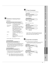
... transmit 'FF' data based on this time, if the data is data read status of the Monitor. Safety Instructions Monitor Overview Connections Basic Operation Sleep Timer Picture & Sound Special Features Transmission / Receiving Protocol Transmission [Command1][Command2][ ][Set ID][ ][Data][Cr] * [Command1] : * [Command2] : * [Set ID] : * [DATA] : * [Cr] : *[ ] : To classify factory-adjustment mode or user-adjustment mode. Adjustment range is not supported.) [02] : not support function (This function doesn't work.) [03] : wait more time (Try again a few...
... transmit 'FF' data based on this time, if the data is data read status of the Monitor. Safety Instructions Monitor Overview Connections Basic Operation Sleep Timer Picture & Sound Special Features Transmission / Receiving Protocol Transmission [Command1][Command2][ ][Set ID][ ][Data][Cr] * [Command1] : * [Command2] : * [Set ID] : * [DATA] : * [Cr] : *[ ] : To classify factory-adjustment mode or user-adjustment mode. Adjustment range is not supported.) [02] : not support function (This function doesn't work.) [03] : wait more time (Try again a few...
Operating Guide
Page 56
... cost of repair or replacement of such a defective product shall be borne by inadequate home antenna or faulty antenna connections, computer software, institutional or commercial use , during the warranty period ("Warranty Period") listed below, effective from the Date of Purchase. * Parts replaced are warranted for proof of warranty, and submit a copy of the bill of user controls, calibration, maintenance or failure to the service person at http...
... cost of repair or replacement of such a defective product shall be borne by inadequate home antenna or faulty antenna connections, computer software, institutional or commercial use , during the warranty period ("Warranty Period") listed below, effective from the Date of Purchase. * Parts replaced are warranted for proof of warranty, and submit a copy of the bill of user controls, calibration, maintenance or failure to the service person at http...

