Owner's Manual
Page 3
... service. 20 Replacement Parts - The unit should be determined by turning the unit "OFF" and "ON", please try to comply with other products (including amplifiers) that produce heat. This equipment generates/uses radio frequencies and, if not installed and used according to the instructions found to be mounted to a wall or ceiling only as to CATV system installer: This reminder is 300 ohm...
... service. 20 Replacement Parts - The unit should be determined by turning the unit "OFF" and "ON", please try to comply with other products (including amplifiers) that produce heat. This equipment generates/uses radio frequencies and, if not installed and used according to the instructions found to be mounted to a wall or ceiling only as to CATV system installer: This reminder is 300 ohm...
Owner's Manual
Page 5
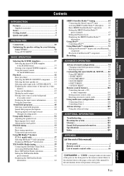
... configurations 74 Changing sound field parameter settings 74 Selecting decoders 79 Customizing this unit (MANUAL SETUP).........82 Using SET MENU 86 1 BASIC MENU 87 2 VOLUME MENU 91 3 SOUND MENU 92 4 INPUT MENU 95 5 OPTION MENU 98 Remote control features 102 Controlling this unit, a TV, or other components 102 Setting remote control codes 104 Resetting all remote control codes 105 Using multi-zone configuration 106 Connecting Zone 2 106 Controlling Zone 2 107 Advanced setup 109 Using the advanced setup 109 ADDITIONAL INFORMATION Troubleshooting 113 Resetting the system 122...
... configurations 74 Changing sound field parameter settings 74 Selecting decoders 79 Customizing this unit (MANUAL SETUP).........82 Using SET MENU 86 1 BASIC MENU 87 2 VOLUME MENU 91 3 SOUND MENU 92 4 INPUT MENU 95 5 OPTION MENU 98 Remote control features 102 Controlling this unit, a TV, or other components 102 Setting remote control codes 104 Resetting all remote control codes 105 Using multi-zone configuration 106 Connecting Zone 2 106 Controlling Zone 2 107 Advanced setup 109 Using the advanced setup 109 ADDITIONAL INFORMATION Troubleshooting 113 Resetting the system 122...
Owner's Manual
Page 6
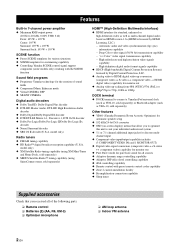
... - channel input ◆ Component video input/output capability includes (3 COMPONENT VIDEO INs and 1 MONITOR OUT) ◆ Digital video signal conversion (composite video ↔ S-video ↔ component video) capability for monitor out ◆ Pure Direct mode for pure hi-fi sound for all sources ◆ Adaptive dynamic range controlling capability ◆ Adaptive DSP effect level controlling capability ◆ iPod controlling capability ◆ Remote control with preset remote control codes capability ◆ Zone 2 custom installation facility ◆ Bi-amplification connection...
... - channel input ◆ Component video input/output capability includes (3 COMPONENT VIDEO INs and 1 MONITOR OUT) ◆ Digital video signal conversion (composite video ↔ S-video ↔ component video) capability for monitor out ◆ Pure Direct mode for pure hi-fi sound for all sources ◆ Adaptive dynamic range controlling capability ◆ Adaptive DSP effect level controlling capability ◆ iPod controlling capability ◆ Remote control with preset remote control codes capability ◆ Zone 2 custom installation facility ◆ Bi-amplification connection...

Owner's Manual
Page 10
... the surround right speaker To the surround back left speaker To the surround To the surround left channel (L), right channel (R), "+" (red) and "-" (black) properly. Input jack Subwoofer cable SUBWOOFER PRE OUT 1 jack y You can also connect another subwoofer to this unit. PRE OUT SUBWOOFER 1 jack AUDIO L MULTI CH INPUT FRONT (8CH) CENTER PRE OUT SINGLE CENTER GND R PHONO IN MD/ OUT CD (PLAY) CD-R (REC) DVD DTV/CBL IN OUT DVR IN OUT VCR SUB SB (8CH) SURROUND WOOFER ZONE 2 HDMI OUT FRONT SURROUND SUR. TOTAL...
... the surround right speaker To the surround back left speaker To the surround To the surround left channel (L), right channel (R), "+" (red) and "-" (black) properly. Input jack Subwoofer cable SUBWOOFER PRE OUT 1 jack y You can also connect another subwoofer to this unit. PRE OUT SUBWOOFER 1 jack AUDIO L MULTI CH INPUT FRONT (8CH) CENTER PRE OUT SINGLE CENTER GND R PHONO IN MD/ OUT CD (PLAY) CD-R (REC) DVD DTV/CBL IN OUT DVR IN OUT VCR SUB SB (8CH) SURROUND WOOFER ZONE 2 HDMI OUT FRONT SURROUND SUR. TOTAL...
Owner's Manual
Page 11
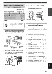
...4 OPTICAL DIGITAL INPUT FZRORONNEETX2/TBPR/RZAEOSSNPEENBCL/E CD DVD 5 6 COAXIAL FRONT A L R DVD IN1 SPEAKERS CENTER SU R Digital coaxial audio output jack Digital coaxial audio cable DVD DIGITAL INPUT COAXIAL jack 2 Connect the video cable to the VIDEO MONITOR OUT jack of this unit and other components VIDEO MONITOR OUT jack DVD DIGITAL INPUT COAXIAL jack DVD VIDEO jack AUDIO L MULTI CH INPUT FRONT (8CH) CENTER PRE OUT SINGLE CENTER GND R PHONO IN MD/ OUT CD (PLAY) CD-R (REC) DVD DTV/CBL IN OUT DVR IN OUT VCR SUB SB (8CH) SURROUND WOOFER ZONE 2 HDMI OUT...
...4 OPTICAL DIGITAL INPUT FZRORONNEETX2/TBPR/RZAEOSSNPEENBCL/E CD DVD 5 6 COAXIAL FRONT A L R DVD IN1 SPEAKERS CENTER SU R Digital coaxial audio output jack Digital coaxial audio cable DVD DIGITAL INPUT COAXIAL jack 2 Connect the video cable to the VIDEO MONITOR OUT jack of this unit and other components VIDEO MONITOR OUT jack DVD DIGITAL INPUT COAXIAL jack DVD VIDEO jack AUDIO L MULTI CH INPUT FRONT (8CH) CENTER PRE OUT SINGLE CENTER GND R PHONO IN MD/ OUT CD (PLAY) CD-R (REC) DVD DTV/CBL IN OUT DVR IN OUT VCR SUB SB (8CH) SURROUND WOOFER ZONE 2 HDMI OUT...

Owner's Manual
Page 14
...TOTAL 0.8A MAX. CONNECTIONS Rear panel 1 2 Connections 34 5 6 7 AUDIO L MULTI CH INPUT FRONT (8CH) CENTER PRE OUT SINGLE CENTER GND R PHONO IN MD/ OUT CD (PLAY) CD-R (REC) DVD DTV/CBL IN OUT DVR IN OUT VCR SUB ZONE 2 SB (8CH) SURROUND WOOFER OUT HDMI FRONT SURROUND SUR. and Canada models only) 2 AUDIO jacks DIGITAL INPUT/OUTPUT jacks 3 MULTI CH INPUT jacks 4 ZONE2 OUT jacks 5 PRE OUT jacks 6 DOCK terminal 7 Video component jacks (VIDEO and S VIDEO) COMPONENT VIDEO jacks 8 ANTENNA terminals 9 REMOTE IN/OUT jacks 0 Speaker terminals A HDMI jacks B VOLTAGE SELECTOR (Asia...
...TOTAL 0.8A MAX. CONNECTIONS Rear panel 1 2 Connections 34 5 6 7 AUDIO L MULTI CH INPUT FRONT (8CH) CENTER PRE OUT SINGLE CENTER GND R PHONO IN MD/ OUT CD (PLAY) CD-R (REC) DVD DTV/CBL IN OUT DVR IN OUT VCR SUB ZONE 2 SB (8CH) SURROUND WOOFER OUT HDMI FRONT SURROUND SUR. and Canada models only) 2 AUDIO jacks DIGITAL INPUT/OUTPUT jacks 3 MULTI CH INPUT jacks 4 ZONE2 OUT jacks 5 PRE OUT jacks 6 DOCK terminal 7 Video component jacks (VIDEO and S VIDEO) COMPONENT VIDEO jacks 8 ANTENNA terminals 9 REMOTE IN/OUT jacks 0 Speaker terminals A HDMI jacks B VOLTAGE SELECTOR (Asia...

Owner's Manual
Page 15
... video monitor should be the same. Connections Placing speakers The speaker layout below shows the speaker setting we recommend. y We recommend that you use of the CINEMA DSP sound field program. The position of the subwoofer is highly recommended for playback the sound of high definition audio formats (Dolby TrueHD, DTS-HD Master Audio, etc.) as well as the Yamaha Active Servo Processing Subwoofer System, is effective not only for reinforcing bass frequencies...
... video monitor should be the same. Connections Placing speakers The speaker layout below shows the speaker setting we recommend. y We recommend that you use of the CINEMA DSP sound field program. The position of the subwoofer is highly recommended for playback the sound of high definition audio formats (Dolby TrueHD, DTS-HD Master Audio, etc.) as well as the Yamaha Active Servo Processing Subwoofer System, is effective not only for reinforcing bass frequencies...

Owner's Manual
Page 18
.... Connect the plain cable to set the "EXTRA SP ASSIGN" parameter in another room (ZONE B), presence speakers, or Zone 2 speakers. Subwoofers (optional) AUDIO L MULTI CH INPUT FRONT (8CH) CENTER PRE OUT SINGLE CENTER GND R PHONO IN MD/ OUT CD (PLAY) CD-R (REC) DVD DTV/CBL IN OUT DVR IN OUT VCR SUB SB (8CH) SURROUND WOOFER ZONE 2 HDMI OUT FRONT SURROUND SUR. TOTAL 0.8A MAX. If the speaker wires are short-circuited, "CHECK SP WIRES" appears in "AUTO SETUP...
.... Connect the plain cable to set the "EXTRA SP ASSIGN" parameter in another room (ZONE B), presence speakers, or Zone 2 speakers. Subwoofers (optional) AUDIO L MULTI CH INPUT FRONT (8CH) CENTER PRE OUT SINGLE CENTER GND R PHONO IN MD/ OUT CD (PLAY) CD-R (REC) DVD DTV/CBL IN OUT DVR IN OUT VCR SUB SB (8CH) SURROUND WOOFER ZONE 2 HDMI OUT FRONT SURROUND SUR. TOTAL 0.8A MAX. If the speaker wires are short-circuited, "CHECK SP WIRES" appears in "AUTO SETUP...
Owner's Manual
Page 25
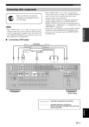
... Coaxial out Audio out DVD player S-video out Video out Component video out HDMI out C LR PR PB Y VS O AUDIO L MULTI CH INPUT FRONT (8CH) CENTER PRE OUT SINGLE CENTER GND R PHONO IN MD/ OUT CD (PLAY) CD-R (REC) DVD DTV/CBL IN OUT DVR IN OUT VCR SUB SB (8CH) SURROUND WOOFER ZONE 2 HDMI OUT FRONT SURROUND SUR. Notes • When "VIDEO CONV." BACK 1 2 SUBWOOFER SIRIUS MD/CD-R MD/CD-R DVD DTV/CBL CD DVD 1 2 3 4 5 6 DIGITAL XM OUTPUT OPTICAL DIGITAL INPUT COAXIAL FRONT B/ZONE B/ ZONE...
... Coaxial out Audio out DVD player S-video out Video out Component video out HDMI out C LR PR PB Y VS O AUDIO L MULTI CH INPUT FRONT (8CH) CENTER PRE OUT SINGLE CENTER GND R PHONO IN MD/ OUT CD (PLAY) CD-R (REC) DVD DTV/CBL IN OUT DVR IN OUT VCR SUB SB (8CH) SURROUND WOOFER ZONE 2 HDMI OUT FRONT SURROUND SUR. Notes • When "VIDEO CONV." BACK 1 2 SUBWOOFER SIRIUS MD/CD-R MD/CD-R DVD DTV/CBL CD DVD 1 2 3 4 5 6 DIGITAL XM OUTPUT OPTICAL DIGITAL INPUT COAXIAL FRONT B/ZONE B/ ZONE...
Owner's Manual
Page 30
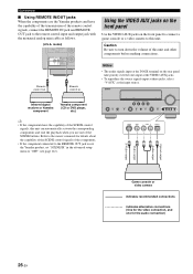
...R O Optical output Audio output Video output S-Video output Game console or video camera indicates recommended connections indicates alternative connections (One for the video connection, and one of this unit. Remote control out Remote control in the advanced setup menu to "OFF" (see page 112). VOLUME SPEAKERS EDIT SEARCH MODE BAND CATEGORY A/B/C/D/E PRESET/TUNING/CH MEMORY INFO ZONE 2 ON/OFF ZONE CONTROL STANDBY /ON SYSTEM OFF PHONES SILENT CINEMA TONE CONTROL SCENE 1 2 3 4 PROGRAM STRAIGHT PURE DIRECT AUDIO SELECT INPUT EFFECT OPTIMIZER MIC VIDEO AUX...
...R O Optical output Audio output Video output S-Video output Game console or video camera indicates recommended connections indicates alternative connections (One for the video connection, and one of this unit. Remote control out Remote control in the advanced setup menu to "OFF" (see page 112). VOLUME SPEAKERS EDIT SEARCH MODE BAND CATEGORY A/B/C/D/E PRESET/TUNING/CH MEMORY INFO ZONE 2 ON/OFF ZONE CONTROL STANDBY /ON SYSTEM OFF PHONES SILENT CINEMA TONE CONTROL SCENE 1 2 3 4 PROGRAM STRAIGHT PURE DIRECT AUDIO SELECT INPUT EFFECT OPTIMIZER MIC VIDEO AUX...

Owner's Manual
Page 34
... battery of the selected input source is input at the HDMI IN jacks (see page 45). • Indicates the current volume level. 0 Input signal indicators Lights up when the adaptive dynamic range control feature is selected as YBA-10, sold separately) connected to the U.S.A. B Sound field indicators Light up when you run "AUTO SETUP" and when the speaker settings set in the standby mode. • Flashes while the connected Yamaha Bluetooth adapter (such as the input source. Note HD...
... battery of the selected input source is input at the HDMI IN jacks (see page 45). • Indicates the current volume level. 0 Input signal indicators Lights up when the adaptive dynamic range control feature is selected as YBA-10, sold separately) connected to the U.S.A. B Sound field indicators Light up when you run "AUTO SETUP" and when the speaker settings set in the standby mode. • Flashes while the connected Yamaha Bluetooth adapter (such as the input source. Note HD...

Owner's Manual
Page 35
... the channel components of the current digital input signal. • Light up or flash according to the set the remote control codes for "SUR.B L/R SP" (see page 43). SP A: The FRONT A speakers are activated. Remote control sensor Approximately 6 m (20 ft) 30 30 Infrared window (1) Outputs infrared control signals. SP B: The FRONT B speakers are connected and a sound field program is in the automatic setup procedure (see page 32) or in the "BASIC MENU" in "MANUAL SETUP...
... the channel components of the current digital input signal. • Light up or flash according to the set the remote control codes for "SUR.B L/R SP" (see page 43). SP A: The FRONT A speakers are activated. Remote control sensor Approximately 6 m (20 ft) 30 30 Infrared window (1) Outputs infrared control signals. SP B: The FRONT B speakers are connected and a sound field program is in the automatic setup procedure (see page 32) or in the "BASIC MENU" in "MANUAL SETUP...

Owner's Manual
Page 36
... video monitor are turned on. ❏ This unit is selected as the front speakers for the adjustment. 2 Connect the supplied optimizer microphone to the OPTIMIZER MIC jack on the front panel. This manual uses the OSD illustrations to explain the "AUTO SETUP" procedure. • Before performing operations, set the operation mode selector on the remote control to FAMP. • This unit uses the speakers connected to the FRONT A speaker terminals as the video input source of the connected subwoofer is set...
... video monitor are turned on. ❏ This unit is selected as the front speakers for the adjustment. 2 Connect the supplied optimizer microphone to the OPTIMIZER MIC jack on the front panel. This manual uses the OSD illustrations to explain the "AUTO SETUP" procedure. • Before performing operations, set the operation mode selector on the remote control to FAMP. • This unit uses the speakers connected to the FRONT A speaker terminals as the video input source of the connected subwoofer is set...

Owner's Manual
Page 56
... mode: - L Surround left speaker FRONT R Front right speaker CENTER Center speaker SUR. y The front panel display turns on the front panel repeatedly to select the high-frequency response (TREBLE) or the low-frequency response (BASS). 2 Rotate the NPROGRAM selector to adjust the balance of bass and treble for level settings) - Display Adjusted speaker FRONT L Front left speaker SUR. operating video functions (video conversion, etc.) • The Pure Direct mode is automatically canceled whenever this unit is in the Pure Direct mode. Enjoying pure hi-fi sound Use...
... mode: - L Surround left speaker FRONT R Front right speaker CENTER Center speaker SUR. y The front panel display turns on the front panel repeatedly to select the high-frequency response (TREBLE) or the low-frequency response (BASS). 2 Rotate the NPROGRAM selector to adjust the balance of bass and treble for level settings) - Display Adjusted speaker FRONT L Front left speaker SUR. operating video functions (video conversion, etc.) • The Pure Direct mode is automatically canceled whenever this unit is in the Pure Direct mode. Enjoying pure hi-fi sound Use...
Owner's Manual
Page 105
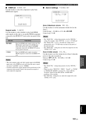
... audio/video signals depend on the power of this unit. setting. is turned on the rear panel of this unit. Choice Functions RX-V863 Plays back HDMI audio signals on another HDMI component connected to the HDMI OUT jack on even if "S.AUDIO" is not available. • The "INI.VOL." setting takes priority over the "INI.VOL." setting does not affect the output level at the HDMI input jacks of the connected video monitor. MAX VOL.;;;+16.5dB INIT. Zone 2 Initial volume INI...
... audio/video signals depend on the power of this unit. setting. is turned on the rear panel of this unit. Choice Functions RX-V863 Plays back HDMI audio signals on another HDMI component connected to the HDMI OUT jack on even if "S.AUDIO" is not available. • The "INI.VOL." setting takes priority over the "INI.VOL." setting does not affect the output level at the HDMI input jacks of the connected video monitor. MAX VOL.;;;+16.5dB INIT. Zone 2 Initial volume INI...
Owner's Manual
Page 117
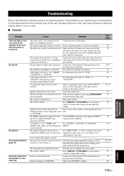
... play the source again. TROUBLESHOOTING Troubleshooting Refer to different types of a short circuit, etc. No sound. "COAX/OPT" or "ANALOG". Audio input jack select is set to "OTHER" and Set "S.AUDIO" to be defective. The front speakers to "RX-V863" in "SP LEVEL". "S.AUDIO" is set to "HDMI", Set Audio input jack select to this unit does not function properly. Non-standard video signals are not secure. The protection circuitry has been activated Check that support the HDCP copy protection standards. Turn...
... play the source again. TROUBLESHOOTING Troubleshooting Refer to different types of a short circuit, etc. No sound. "COAX/OPT" or "ANALOG". Audio input jack select is set to "OTHER" and Set "S.AUDIO" to be defective. The front speakers to "RX-V863" in "SP LEVEL". "S.AUDIO" is set to "HDMI", Set Audio input jack select to this unit does not function properly. Non-standard video signals are not secure. The protection circuitry has been activated Check that support the HDCP copy protection standards. Turn...

Owner's Manual
Page 119
... shock (such as a DVD player. Set "MEMORY GUARD" to the analog AUDIO IN jacks. Disconnect the power cable from such equipment. See page - 21, 23 - 23 100 - - 14 - - ■ HDMI Problem Cause No picture or sound. "CHECK SP WIRES" appears in "SET MENU" is disturbed. Turn on . Connect the source component to prevent dubbing. Remedy Reduce the number of the connected HDMI components. A source cannot be changed. Some components cannot record Dolby Digital or DTS sources. (U.S.A. The internal temperature...
... shock (such as a DVD player. Set "MEMORY GUARD" to the analog AUDIO IN jacks. Disconnect the power cable from such equipment. See page - 21, 23 - 23 100 - - 14 - - ■ HDMI Problem Cause No picture or sound. "CHECK SP WIRES" appears in "SET MENU" is disturbed. Turn on . Connect the source component to prevent dubbing. Remedy Reduce the number of the connected HDMI components. A source cannot be changed. Some components cannot record Dolby Digital or DTS sources. (U.S.A. The internal temperature...
Owner's Manual
Page 122
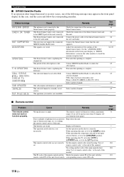
... SiriusConnect tuner. Set the operation mode selector correctly. When operating the component selected by the input selector button, set it to the SiriusConnect tuner properly. Status message ANTENNA ERROR CHECK SR TUNER NOT SUPPORTED ACQUIRING UPDATING F/W UPDATING CALL SIRIUS (CALL 888-539SIRIUS TO SUBSCRIBE) SUB UPDATED INVALID Not Available Cause Remedy The antenna is complete. The SiriusConnect tuner is not connected to the AC wall outlet. Contact SIRIUS Satellite Radio to subscribe the selected channel...
... SiriusConnect tuner. Set the operation mode selector correctly. When operating the component selected by the input selector button, set it to the SiriusConnect tuner properly. Status message ANTENNA ERROR CHECK SR TUNER NOT SUPPORTED ACQUIRING UPDATING F/W UPDATING CALL SIRIUS (CALL 888-539SIRIUS TO SUBSCRIBE) SUB UPDATED INVALID Not Available Cause Remedy The antenna is complete. The SiriusConnect tuner is not connected to the AC wall outlet. Contact SIRIUS Satellite Radio to subscribe the selected channel...

Owner's Manual
Page 133
... remote control codes resetting 104 AM antenna connection 27 AM tuning 53 Amplifier function OSD display time, Display settings 98 ANTENNA ERROR, SIRIUS Satellite Radio status message 118 Audio and video synchronization, Sound menu 94 Audio cable plugs 17 Audio components connection 23 Audio information 46 Audio input jacks selection 44 AUDIO jacks 17 Audio jacks 17 AUDIO SELECT 44 AUDIO SELECT, Initial configuration 100 Audio select, Initial configuration 100 Audio signal flow 19 Auto delay, Lip sync 94 AUTO SETUP 32, 82 Auto setup 82 AUTO SETUP, Troubleshooting .......120...
... remote control codes resetting 104 AM antenna connection 27 AM tuning 53 Amplifier function OSD display time, Display settings 98 ANTENNA ERROR, SIRIUS Satellite Radio status message 118 Audio and video synchronization, Sound menu 94 Audio cable plugs 17 Audio components connection 23 Audio information 46 Audio input jacks selection 44 AUDIO jacks 17 Audio jacks 17 AUDIO SELECT 44 AUDIO SELECT, Initial configuration 100 Audio select, Initial configuration 100 Audio signal flow 19 Auto delay, Lip sync 94 AUTO SETUP 32, 82 Auto setup 82 AUTO SETUP, Troubleshooting .......120...
Owner's Manual
Page 136
... Sports, Sound field program 49 SR LEVEL, Sound field parameter 79 SR PIN, Advanced setup 112 Standard, Sound field program 49 STANDBY CHARGE, Input menu 96 Standby mode, Main zone 29 Standby mode, Zone 2 108 START PAIRING, Input menu ...........97 STEREO, Sound field category ...........50 Straight 51 Straight Enhancer, Sound field program 50 STRAIGHT mode 51 SUB UPDATED, SIRIUS Satellite Radio status message 118 SUBWOOFER PHASE, Speaker settings 89 Subwoofer phase, Speaker settings ......89 SUBWOOFER PRE OUT jack connection 24 Supplied accessories 2 Support audio, HDMI set 101...
... Sports, Sound field program 49 SR LEVEL, Sound field parameter 79 SR PIN, Advanced setup 112 Standard, Sound field program 49 STANDBY CHARGE, Input menu 96 Standby mode, Main zone 29 Standby mode, Zone 2 108 START PAIRING, Input menu ...........97 STEREO, Sound field category ...........50 Straight 51 Straight Enhancer, Sound field program 50 STRAIGHT mode 51 SUB UPDATED, SIRIUS Satellite Radio status message 118 SUBWOOFER PHASE, Speaker settings 89 Subwoofer phase, Speaker settings ......89 SUBWOOFER PRE OUT jack connection 24 Supplied accessories 2 Support audio, HDMI set 101...


