Owners Manual
Page 2
... Please record the serial number of cable entry as power-supply cord or plug is too late, YAMAHA and the Electronic Industries Association's Consumer Electronics Group recommend you to the presence of electric shock to constitute a risk of important operating and maintenance (servicing) instructions in any way, such as practical. Retain this apparatus near any ventilation openings. When a cart is...
... Please record the serial number of cable entry as power-supply cord or plug is too late, YAMAHA and the Electronic Industries Association's Consumer Electronics Group recommend you to the presence of electric shock to constitute a risk of important operating and maintenance (servicing) instructions in any way, such as practical. Retain this apparatus near any ventilation openings. When a cart is...
Owners Manual
Page 4
...power plug from the wall outlet. 19 VOLTAGE SELECTOR (Asia and General models only) The VOLTAGE SELECTOR on switches, knobs and/or cords. 10 When disconnecting the power cable from use this unit by lightning, keep the power cord and outdoor antennas disconnected from direct sunlight, heat sources, vibration, dust, moisture, and/or cold. YAMAHA will not be held responsible for any service is connected... 8 Do not operate this sound system in them, as they may overheat, possibly causing damage. 9 Do not use force on the rear panel of plug to this unit, press MASTER ON/OFF to ...
...power plug from the wall outlet. 19 VOLTAGE SELECTOR (Asia and General models only) The VOLTAGE SELECTOR on switches, knobs and/or cords. 10 When disconnecting the power cable from use this unit by lightning, keep the power cord and outdoor antennas disconnected from direct sunlight, heat sources, vibration, dust, moisture, and/or cold. YAMAHA will not be held responsible for any service is connected... 8 Do not operate this sound system in them, as they may overheat, possibly causing damage. 9 Do not use force on the rear panel of plug to this unit, press MASTER ON/OFF to ...
Owners Manual
Page 5
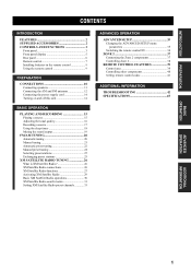
... CONTROLS AND FUNCTIONS 3 Front panel 3 Front panel display 5 Rear panel 6 Remote control 7 Installing batteries in the remote control 9 Using the remote control 9 PREPARATION CONNECTIONS 10 Connecting speakers 11 Connecting the AM and FM antennas 12 Connecting the power supply cord 14 Turning on and off this unit 14 BASIC OPERATION PLAYING AND RECORDING 15 Playing a source 15 Adjusting the tonal quality 16 Recording a source 17 Using the sleep timer 18 Muting the sound output 19 FM/AM TUNING 20 Automatic tuning 20 Manual tuning 21 Automatic preset tuning 22 Manual preset...
... CONTROLS AND FUNCTIONS 3 Front panel 3 Front panel display 5 Rear panel 6 Remote control 7 Installing batteries in the remote control 9 Using the remote control 9 PREPARATION CONNECTIONS 10 Connecting speakers 11 Connecting the AM and FM antennas 12 Connecting the power supply cord 14 Turning on and off this unit 14 BASIC OPERATION PLAYING AND RECORDING 15 Playing a source 15 Adjusting the tonal quality 16 Recording a source 17 Using the sleep timer 18 Muting the sound output 19 FM/AM TUNING 20 Automatic tuning 20 Manual tuning 21 Automatic preset tuning 22 Manual preset...
Owners Manual
Page 6
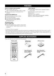
... loop antenna Indoor FM antenna (Europe and Australia models) 2 Remote control POWER POWER TV AV STANDBY POWER CD MD/TAPE TUNER XM DVD DTV/CBL VCR PHONO REC DISC SKIP TV CODE SET SPEAKERS A B SLEEP VOL CH VOLUME MUTE INPUT 1 2 5 6 9 0 MUTE 3 4 7 8 10 ENT. RETURN MEMORY PRESET/CH MENU SRCH MODE A-E/CAT. TITLE BAND ENTER A-E/CAT. Design and specifications are given in parentheses. • This manual is printed prior to change in 2-channel power amplifier ◆ Minimum RMS output power...
... loop antenna Indoor FM antenna (Europe and Australia models) 2 Remote control POWER POWER TV AV STANDBY POWER CD MD/TAPE TUNER XM DVD DTV/CBL VCR PHONO REC DISC SKIP TV CODE SET SPEAKERS A B SLEEP VOL CH VOLUME MUTE INPUT 1 2 5 6 9 0 MUTE 3 4 7 8 10 ENT. RETURN MEMORY PRESET/CH MENU SRCH MODE A-E/CAT. TITLE BAND ENTER A-E/CAT. Design and specifications are given in parentheses. • This manual is printed prior to change in 2-channel power amplifier ◆ Minimum RMS output power...

Owners Manual
Page 7
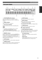
... Zone 2 is turned on Zone 2 or set it outward to the OFF position to turn on the power of this unit. See page 14 for details. Note This switch is operational only when MASTER ON/OFF is selected as the input source of Zone 2. 5 Remote control sensor Receives infrared signals from the remote control. (U.S.A. INTRODUCTION Front panel 1 2 CONTROLS AND FUNCTIONS CONTROLS AND FUNCTIONS 3 45 6 78 9 0 A B C D MASTER ON OFF MAIN ZONE ON/OFF INPUT ZONE 2 ON/OFF ZONE CONTROL FM/AM l TUNING...
... Zone 2 is turned on Zone 2 or set it outward to the OFF position to turn on the power of this unit. See page 14 for details. Note This switch is operational only when MASTER ON/OFF is selected as the input source of Zone 2. 5 Remote control sensor Receives infrared signals from the remote control. (U.S.A. INTRODUCTION Front panel 1 2 CONTROLS AND FUNCTIONS CONTROLS AND FUNCTIONS 3 45 6 78 9 0 A B C D MASTER ON OFF MAIN ZONE ON/OFF INPUT ZONE 2 ON/OFF ZONE CONTROL FM/AM l TUNING...
Owners Manual
Page 8
... front panel display between channel categories or selects the preset channel group when XM is selected as the input source (see page 25). The indicator above it lights up when this unit to 8) directly when TUNER or XM is selected as the input source (see page 31). Note Press SPEAKERS A/B so that the SP A/B indicators turn off the function (the indicator turns off the speaker set connected to high and low-frequency ranges at a low volume level...
... front panel display between channel categories or selects the preset channel group when XM is selected as the input source (see page 25). The indicator above it lights up when this unit to 8) directly when TUNER or XM is selected as the input source (see page 31). Note Press SPEAKERS A/B so that the SP A/B indicators turn off the function (the indicator turns off the speaker set connected to high and low-frequency ranges at a low volume level...
Owners Manual
Page 9
... is flashing, store the displayed station in the system memory by using A/B/C/D/E and one of each Radio Data System mode lights up when the Radio Data System station that offers the EON data service is only applicable to the set of speakers are selected. 2 ZONE 2 indicator Lights up when Zone 2 is turned on. 3 Input source indicators Light up when this unit is receiving a strong signal for an FM stereo broadcast while the AUTO indicator...
... is flashing, store the displayed station in the system memory by using A/B/C/D/E and one of each Radio Data System mode lights up when the Radio Data System station that offers the EON data service is only applicable to the set of speakers are selected. 2 ZONE 2 indicator Lights up when Zone 2 is turned on. 3 Input source indicators Light up when this unit is receiving a strong signal for an FM stereo broadcast while the AUTO indicator...

Owners Manual
Page 10
...for connection information. 6 CD jacks Connect a CD player. See page 26 for connection information. 8 ZONE 2 jacks Connect a Zone 2 component. A AC OUTLET(S) (SWITCHED) Use to supply power to input/output remote control signals. Voltages are used to your local main voltage BEFORE plugging the power supply cord into the AC wall outlet. See page 10 for connections information. 2 AUDIO/VIDEO jacks Connect audio and video components. See page 12 for connection information. 7 PHONO jacks and GND terminal Connect a turntable. CONTROLS AND FUNCTIONS Rear panel 1 2 34 5 TUNER GND...
...for connection information. 6 CD jacks Connect a CD player. See page 26 for connection information. 8 ZONE 2 jacks Connect a Zone 2 component. A AC OUTLET(S) (SWITCHED) Use to supply power to input/output remote control signals. Voltages are used to your local main voltage BEFORE plugging the power supply cord into the AC wall outlet. See page 10 for connections information. 2 AUDIO/VIDEO jacks Connect audio and video components. See page 12 for connection information. 7 PHONO jacks and GND terminal Connect a turntable. CONTROLS AND FUNCTIONS Rear panel 1 2 34 5 TUNER GND...
Owners Manual
Page 11
.... DISPLAY 9 0 A B C D E F (U.S.A. To operate other components using this unit or other components made by YAMAHA or other audio and video components are the same as the input source (see page 39). 3 Numeric buttons Select the preset station number (1 to 8) when TUNER is pressed inward to the ON position. • In the standby mode, this unit consumes a small amount of power to receive infrared signals from the remote control. • This button does not set Zone 2 to the standby mode. 8 POWER Turns on...
.... DISPLAY 9 0 A B C D E F (U.S.A. To operate other components using this unit or other components made by YAMAHA or other audio and video components are the same as the input source (see page 39). 3 Numeric buttons Select the preset station number (1 to 8) when TUNER is pressed inward to the ON position. • In the standby mode, this unit consumes a small amount of power to receive infrared signals from the remote control. • This button does not set Zone 2 to the standby mode. 8 POWER Turns on...

Owners Manual
Page 12
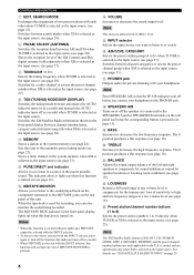
... FUNCTIONS 9 SPEAKERS A/B Turns on or off the set up remote control codes (see page 19). C MUTE Mutes the sound output. F DISPLAY Switches the XM Satellite Radio information shown in the front panel display between the XM Satellite Radio search modes (see "XM SATELLITE RADIO TUNING" on the front panel rotates. B VOLUME +/- Increases or decreases the sound output level. E SRCH (SEARCH) MODE Switches between channel number/name, category and artist name/song title when XM is selected as the input source. model...
... FUNCTIONS 9 SPEAKERS A/B Turns on or off the set up remote control codes (see page 19). C MUTE Mutes the sound output. F DISPLAY Switches the XM Satellite Radio information shown in the front panel display between the XM Satellite Radio search modes (see "XM SATELLITE RADIO TUNING" on the front panel rotates. B VOLUME +/- Increases or decreases the sound output level. E SRCH (SEARCH) MODE Switches between channel number/name, category and artist name/song title when XM is selected as the input source. model...

Owners Manual
Page 14
... sound will be heard from the speakers, and if the polarity of this unit. Digital TV, Cable TV DVD player VCR, etc. FM ANT VIDEO DVD DTV/ CBL IN VCR OUT AUDIO CD GND MONITOR OUT AUDIO DVD DTV/ CBL IN (PLAY) VCR OUT (REC) IN (PLAY) MD/TAPE OUT (REC) OUTPUT SUB WOOFER PHONO ZONE 2 OUTPUT REMOTE IN OUT +- -+ XM SPEAKERS A B RL RL V RL RL +- -+ Audio out Audio in Video in Audio out Video...
... sound will be heard from the speakers, and if the polarity of this unit. Digital TV, Cable TV DVD player VCR, etc. FM ANT VIDEO DVD DTV/ CBL IN VCR OUT AUDIO CD GND MONITOR OUT AUDIO DVD DTV/ CBL IN (PLAY) VCR OUT (REC) IN (PLAY) MD/TAPE OUT (REC) OUTPUT SUB WOOFER PHONO ZONE 2 OUTPUT REMOTE IN OUT +- -+ XM SPEAKERS A B RL RL V RL RL +- -+ Audio out Audio in Video in Audio out Video...

Owners Manual
Page 15
... the power supply to either the SPEAKERS A or B terminals. • Use speakers with the specified impedance shown on the rear panel of this unit. ■ IMPEDANCE SELECTOR CAUTION Do not slide the IMPEDANCE SELECTOR switch while the power of each terminal. Left If you use two sets (A and B), the impedance of each speaker must be connected to this unit fails to turn on...
... the power supply to either the SPEAKERS A or B terminals. • Use speakers with the specified impedance shown on the rear panel of this unit. ■ IMPEDANCE SELECTOR CAUTION Do not slide the IMPEDANCE SELECTOR switch while the power of each terminal. Left If you use two sets (A and B), the impedance of each speaker must be connected to this unit fails to turn on...

Owners Manual
Page 39
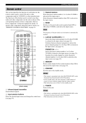
... remote control ID of this unit. Remote REMOTE Use to operate this unit. The power of this unit is muted. • During the ADVANCED SETUP procedure, only MASTER ON/OFF, A/B/C/D/E and the preset station/channel number buttons (1 and 2) on the front panel are operational. 1,2,5 MASTER ON OFF MAIN ZONE ON/OFF INPUT ZONE 2 ON/OFF ZONE CONTROL FM/AM l TUNING/CH h XM/ANT EDIT MEMORY TUN MODE/DISP SEARCH MODE MAN'L/AUTO FM AUTO/MAN'L A/B/C/D/E 1 CATEGORY PHONES SPEAKERS A B 2 3 4 5 6 BASS...
... remote control ID of this unit. Remote REMOTE Use to operate this unit. The power of this unit is muted. • During the ADVANCED SETUP procedure, only MASTER ON/OFF, A/B/C/D/E and the preset station/channel number buttons (1 and 2) on the front panel are operational. 1,2,5 MASTER ON OFF MAIN ZONE ON/OFF INPUT ZONE 2 ON/OFF ZONE CONTROL FM/AM l TUNING/CH h XM/ANT EDIT MEMORY TUN MODE/DISP SEARCH MODE MAN'L/AUTO FM AUTO/MAN'L A/B/C/D/E 1 CATEGORY PHONES SPEAKERS A B 2 3 4 5 6 BASS...
Owners Manual
Page 40
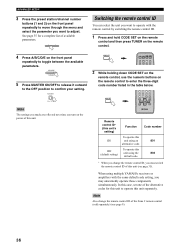
... MEMORY PRESET/CH MENU SRCH MODE A-E/CAT. Note Also change the remote control ID, you must switch the remote control ID of this unit (see page 9). 36 ADVANCED SETUP 3 Press the preset station/channel number buttons (1 and 2) on the front panel repeatedly to move through the menu and select the parameter you want to operate with the same default code setting, you may unwantedly operate those components simultaneously. CODE SET MENU POWER POWER TV AV STANDBY POWER CD MD/TAPE TUNER XM DVD DTV...
... MEMORY PRESET/CH MENU SRCH MODE A-E/CAT. Note Also change the remote control ID, you must switch the remote control ID of this unit (see page 9). 36 ADVANCED SETUP 3 Press the preset station/channel number buttons (1 and 2) on the front panel repeatedly to move through the menu and select the parameter you want to operate with the same default code setting, you may unwantedly operate those components simultaneously. CODE SET MENU POWER POWER TV AV STANDBY POWER CD MD/TAPE TUNER XM DVD DTV...

Owners Manual
Page 44
... control other audio and video components made by YAMAHA and other components, you must set the appropriate remote control codes. 1 2 3 4 5 POWER POWER TV AV STANDBY POWER CD MD/TAPE TUNER XM DVD DTV/CBL VCR PHONO REC DISC SKIP TV CODE SET SPEAKERS A B SLEEP VOL CH VOLUME MUTE INPUT MUTE 6 7 8 9 MUTE INPUT 1 2 5 6 9 0 MUTE 3 4 7 8 10 ENT. DISPLAY 0 A B C D 1 AV POWER 2 TV POWER 3 ll hh b a REC/ DISC SKIP s e h 4 TV VOL + TV VOL - 5 TV CH + TV CH - 6 TV MUTE 7 TITLE 8 ENTER DVD player Power *1 VCR Power *1 Digital TV/ Cable...
... control other audio and video components made by YAMAHA and other components, you must set the appropriate remote control codes. 1 2 3 4 5 POWER POWER TV AV STANDBY POWER CD MD/TAPE TUNER XM DVD DTV/CBL VCR PHONO REC DISC SKIP TV CODE SET SPEAKERS A B SLEEP VOL CH VOLUME MUTE INPUT MUTE 6 7 8 9 MUTE INPUT 1 2 5 6 9 0 MUTE 3 4 7 8 10 ENT. DISPLAY 0 A B C D 1 AV POWER 2 TV POWER 3 ll hh b a REC/ DISC SKIP s e h 4 TV VOL + TV VOL - 5 TV CH + TV CH - 6 TV MUTE 7 TITLE 8 ENTER DVD player Power *1 VCR Power *1 Digital TV/ Cable...
Owners Manual
Page 45
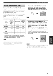
... code, try setting other components by setting the appropriate remote control codes. CODE SET MENU POWER POWER TV AV STANDBY POWER CD MD/TAPE TUNER XM DVD DTV/CBL VCR PHONO Note You must press and hold CODE SET on the remote control and then press one remote control code to each input selector button. ADVANCED OPERATION 41 In this case, try setting each input source listed in the front panel display. RETURN MEMORY PRESET/CH MENU SRCH MODE A-E/CAT. Codes can be set up . To reset the code...
... code, try setting other components by setting the appropriate remote control codes. CODE SET MENU POWER POWER TV AV STANDBY POWER CD MD/TAPE TUNER XM DVD DTV/CBL VCR PHONO Note You must press and hold CODE SET on the remote control and then press one remote control code to each input selector button. ADVANCED OPERATION 41 In this case, try setting each input source listed in the front panel display. RETURN MEMORY PRESET/CH MENU SRCH MODE A-E/CAT. Codes can be set up . To reset the code...
Owners Manual
Page 46
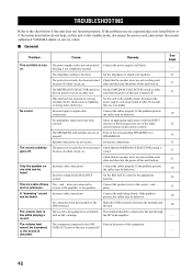
.... Connect the speaker wires to either the rear panel is not set Turn on . Connect the audio plugs firmly. The volume level is incorrect. the MC head amplifier. See page - 11 11 11 - 10 15 15 11 11 11 10 16 11 10 10 - - 42 TROUBLESHOOTING TROUBLESHOOTING Refer to the chart below do not help, set this unit to the standby mode, disconnect the power cord, and contact the nearest authorized YAMAHA...
.... Connect the speaker wires to either the rear panel is not set Turn on . Connect the audio plugs firmly. The volume level is incorrect. the MC head amplifier. See page - 11 11 11 - 10 15 15 11 11 11 10 16 11 10 10 - - 42 TROUBLESHOOTING TROUBLESHOOTING Refer to the chart below do not help, set this unit to the standby mode, disconnect the power cord, and contact the nearest authorized YAMAHA...

Owners Manual
Page 47
... or the antenna input is poor. Try using the manual tuning method. There are A TV set is being received may result from the TV set to the FLAT position. 16 Using the BASS, The PURE DIRECT button is turned on the power of this unit. ADDITIONAL INFORMATION 43 There is There is too weak. The signal is multipath interference. Preset the stations again. The desired station cannot be...
... or the antenna input is poor. Try using the manual tuning method. There are A TV set is being received may result from the TV set to the FLAT position. 16 Using the BASS, The PURE DIRECT button is turned on the power of this unit. ADDITIONAL INFORMATION 43 There is There is too weak. The signal is multipath interference. Preset the stations again. The desired station cannot be...
Owners Manual
Page 48
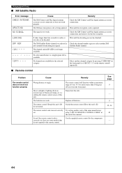
...-Play digital antenna accessory connections. No channels are weak. Use the supplied remote control for audio or text data to the remote control. Cause Remedy Wrong distance or angle. Wait until the encryption code is available. TROUBLESHOOTING ■ XM Satellite Radio Error message CHECK ANTENNA UPDATING NO SIGNAL LOADING OFF AIR - - - The XM user encryption code is not connected, or does not work nor function properly. j / i on the front panel (or A-E/CAT. The remote control will function...
...-Play digital antenna accessory connections. No channels are weak. Use the supplied remote control for audio or text data to the remote control. Cause Remedy Wrong distance or angle. Wait until the encryption code is available. TROUBLESHOOTING ■ XM Satellite Radio Error message CHECK ANTENNA UPDATING NO SIGNAL LOADING OFF AIR - - - The XM user encryption code is not connected, or does not work nor function properly. j / i on the front panel (or A-E/CAT. The remote control will function...
Owners Manual
Page 53
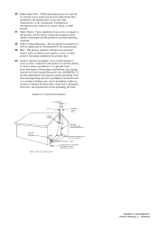
... any service or repairs to this product, ask the service technician to perform safety checks to provide some protection against voltage surges and built-up static charges. PART H) Printed in proper operating condition. 22 Wall or Ceiling Mounting - NATIONAL ELECTRICAL CODE ANTENNA LEAD IN WIRE ANTENNA DISCHARGE UNIT (NEC SECTION 810-20) GROUNDING CONDUCTORS (NEC SECTION 810-21) GROUND CLAMPS POWER SERVICE GROUNDING...
... any service or repairs to this product, ask the service technician to perform safety checks to provide some protection against voltage surges and built-up static charges. PART H) Printed in proper operating condition. 22 Wall or Ceiling Mounting - NATIONAL ELECTRICAL CODE ANTENNA LEAD IN WIRE ANTENNA DISCHARGE UNIT (NEC SECTION 810-20) GROUNDING CONDUCTORS (NEC SECTION 810-21) GROUND CLAMPS POWER SERVICE GROUNDING...


