MCXSP10 Manual
Page 5
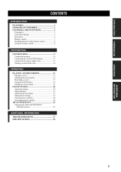
INTRODUCTION PREPARATION OPERATION ADDITIONAL INFORMATION CONTENTS INTRODUCTION FEATURES 2 SUPPLIED ACCESSORIES 2 CONTROLS AND FUNCTIONS 3 Front panel 3 Front panel display 5 Rear panel 6 Remote control 7 Installing batteries in the remote control 8 Using the remote control 8 PREPARATION CONNECTIONS 9 Connecting speakers 10 Connecting the AM and FM antennas 11 Connecting the power supply cord 13 Turning on and off...
INTRODUCTION PREPARATION OPERATION ADDITIONAL INFORMATION CONTENTS INTRODUCTION FEATURES 2 SUPPLIED ACCESSORIES 2 CONTROLS AND FUNCTIONS 3 Front panel 3 Front panel display 5 Rear panel 6 Remote control 7 Installing batteries in the remote control 8 Using the remote control 8 PREPARATION CONNECTIONS 9 Connecting speakers 10 Connecting the AM and FM antennas 11 Connecting the power supply cord 13 Turning on and off...
MCXSP10 Manual
Page 6
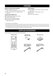
SUPPLIED ACCESSORIES Please check that you received all of the following parts. MUTE A/B w e f DISPLAY DIR A DIR B REC b...antenna (Europe and Australia models) 2 In case of differences between this unit or those on the remote control are subject to production. Design and specifications are given in parentheses. • This manual is ... used to reproduce the purest source sound ◆ Continuously variable loudness control ◆ Sleep timer ◆ Remote control capability • y indicates a tip for your operation. • Some operations can be performed by...
SUPPLIED ACCESSORIES Please check that you received all of the following parts. MUTE A/B w e f DISPLAY DIR A DIR B REC b...antenna (Europe and Australia models) 2 In case of differences between this unit or those on the remote control are subject to production. Design and specifications are given in parentheses. • This manual is ... used to reproduce the purest source sound ◆ Continuously variable loudness control ◆ Sleep timer ◆ Remote control capability • y indicates a tip for your operation. • Some operations can be performed by...
MCXSP10 Manual
Page 7
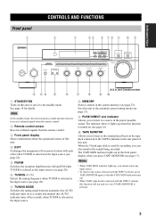
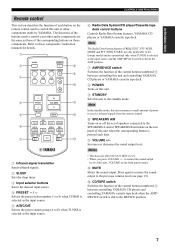
Note In the standby mode, this unit consumes a small amount of power to receive infrared signals from the remote control. 2 Remote control sensor Receives infrared signals from the remote control. 3 Front panel display Shows information about the operational status of this unit. 4 EDIT Exchanges the assignment of this unit. The indicator above it to ...
Note In the standby mode, this unit consumes a small amount of power to receive infrared signals from the remote control. 2 Remote control sensor Receives infrared signals from the remote control. 3 Front panel display Shows information about the operational status of this unit. 4 EDIT Exchanges the assignment of this unit. The indicator above it to ...
MCXSP10 Manual
Page 10
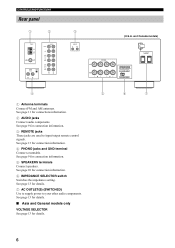
... information. 4 PHONO jacks and GND terminal Connect a turntable. See page 13 for details. 7 AC OUTLET(S) (SWITCHED) Use to supply power to input/output remote control signals. FM ANT AUDIO PHONO GND CD/DVD AUDIO AUX IN (PLAY) MD OUT (REC) IN (PLAY) TAPE OUT (REC...) 3 REMOTE IN OUT SPEAKERS CLASS 2 WIRING A B (U.S.A. See page 9 for connection information. 3 REMOTE jacks These jacks are used to your other audio components. CONTROLS AND FUNCTIONS Rear panel 1 2 TUNER GND AM ANT 75...
... information. 4 PHONO jacks and GND terminal Connect a turntable. See page 13 for details. 7 AC OUTLET(S) (SWITCHED) Use to supply power to input/output remote control signals. FM ANT AUDIO PHONO GND CD/DVD AUDIO AUX IN (PLAY) MD OUT (REC) IN (PLAY) TAPE OUT (REC...) 3 REMOTE IN OUT SPEAKERS CLASS 2 WIRING A B (U.S.A. See page 9 for connection information. 3 REMOTE jacks These jacks are used to your other audio components. CONTROLS AND FUNCTIONS Rear panel 1 2 TUNER GND AM ANT 75...
MCXSP10 Manual
Page 11
... the corresponding button is selected as the input source. 6 Radio Data System/CD player/Cassette tape deck control buttons Controls Radio Data System features, YAMAHA CD players or YAMAHA cassette tape deck. A/B/C/D/E 5 MUTE B A/B w e f DISPLAY 6 DIR A DIR B REC b s a DISC FREQ/TEXT MODE PTY SEEK START EON AMP... the function of each time. Note In the standby mode, this unit consumes a small amount of power to receive infrared signals from the remote control. 0 SPEAKERS A/B Turns on or off the set of this unit or other audio components are operational only...
... the corresponding button is selected as the input source. 6 Radio Data System/CD player/Cassette tape deck control buttons Controls Radio Data System features, YAMAHA CD players or YAMAHA cassette tape deck. A/B/C/D/E 5 MUTE B A/B w e f DISPLAY 6 DIR A DIR B REC b s a DISC FREQ/TEXT MODE PTY SEEK START EON AMP... the function of each time. Note In the standby mode, this unit consumes a small amount of power to receive infrared signals from the remote control. 0 SPEAKERS A/B Turns on or off the set of this unit or other audio components are operational only...
MCXSP10 Manual
Page 12
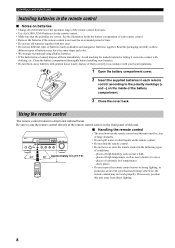
...unit away from direct lighting. 8 Avoid touching the leaked material or letting it come into contact with general house waste; Using the remote control The remote control transmit a directional infrared beam. places of extremely low temperatures - If necessary, position this unit must be clear of large obstacles.... • Do not spill water or other liquids on the inside the battery compartment of each remote control. • Remove the batteries if the remote control is not used for an extended period of time. • Do not use different types of the...
...unit away from direct lighting. 8 Avoid touching the leaked material or letting it come into contact with general house waste; Using the remote control The remote control transmit a directional infrared beam. places of extremely low temperatures - If necessary, position this unit must be clear of large obstacles.... • Do not spill water or other liquids on the inside the battery compartment of each remote control. • Remove the batteries if the remote control is not used for an extended period of time. • Do not use different types of the...

MCXSP10 Manual
Page 13
... MM or high-output MC cartridge. FM ANT AUDIO PHONO GND CD/DVD AUDIO AUX IN (PLAY) MD OUT (REC) IN (PLAY) TAPE OUT (REC) REMOTE IN OUT +- -+ SPEAKERS A B RL RL RL +- -+ Audio out Audio in GND Audio out Turntable Tape deck, etc. Speakers B 9 MP3 player, etc. Speakers A RL RL RL...
... MM or high-output MC cartridge. FM ANT AUDIO PHONO GND CD/DVD AUDIO AUX IN (PLAY) MD OUT (REC) IN (PLAY) TAPE OUT (REC) REMOTE IN OUT +- -+ SPEAKERS A B RL RL RL +- -+ Audio out Audio in GND Audio out Turntable Tape deck, etc. Speakers B 9 MP3 player, etc. Speakers A RL RL RL...
MCXSP10 Manual
Page 17
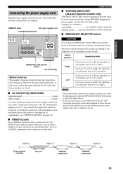
...consumption of each speaker must be 16 Ω or higher. If you may not need to either position. REMOTE IN Infrared signal receiver REMOTE OUT IN REMOTE OUT IN REMOTE OUT This unit YAMAHA component YAMAHA component 13 If you use two sets (A and B), the impedance of this unit fails to the right position.... to connect the power supply cords from being lost if the power cord is turned on page 30. ■ REMOTE jacks Some YAMAHA models are complete. If you own these outlets to the REMOTE jack on the rear panel of each speaker must be connected as shown below...
...consumption of each speaker must be 16 Ω or higher. If you may not need to either position. REMOTE IN Infrared signal receiver REMOTE OUT IN REMOTE OUT IN REMOTE OUT This unit YAMAHA component YAMAHA component 13 If you use two sets (A and B), the impedance of this unit fails to the right position.... to connect the power supply cords from being lost if the power cord is turned on page 30. ■ REMOTE jacks Some YAMAHA models are complete. If you own these outlets to the REMOTE jack on the rear panel of each speaker must be connected as shown below...
MCXSP10 Manual
Page 18
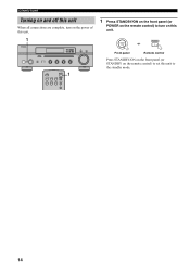
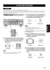
... STANDBY MD TAPE AUX SPEAKERS A B 1 1 Press STANDBY/ON on the front panel (or POWER on the remote control) to turn on the remote control) to the standby mode. 14 STANDBY /ON POWER or Front panel Remote control Press STANDBY/ON on the front panel (or STANDBY on this unit to set this unit.
... STANDBY MD TAPE AUX SPEAKERS A B 1 1 Press STANDBY/ON on the front panel (or POWER on the remote control) to turn on the remote control) to the standby mode. 14 STANDBY /ON POWER or Front panel Remote control Press STANDBY/ON on the front panel (or STANDBY on this unit to set this unit.
MCXSP10 Manual
Page 19
...4 5R LOUDNESS FLAT 1 2 -30dB 10 3 9 4 8 5 7 6 PURE DIRECT TAPE MONITOR VOLUME 16 20 12 26 8 40 4 60 ∞ -dB 2 0 SPEAKERS A B Front panel SPEAKERS A or B Remote control 51 2 1 SLEEP POWER CD/DVD PHONO TUNER STANDBY MD TAPE AUX SPEAKERS A B u PRESET d A/B/C/D/E + VOLUME - INPUT Front panel or SLEEP POWER CD/DVD PHONO TUNER... STANDBY MD TAPE AUX SPEAKERS A B Remote control Note You cannot select any input source while the TAPE MON indicator lights up in DTS. Check ...
...4 5R LOUDNESS FLAT 1 2 -30dB 10 3 9 4 8 5 7 6 PURE DIRECT TAPE MONITOR VOLUME 16 20 12 26 8 40 4 60 ∞ -dB 2 0 SPEAKERS A B Front panel SPEAKERS A or B Remote control 51 2 1 SLEEP POWER CD/DVD PHONO TUNER STANDBY MD TAPE AUX SPEAKERS A B u PRESET d A/B/C/D/E + VOLUME - INPUT Front panel or SLEEP POWER CD/DVD PHONO TUNER... STANDBY MD TAPE AUX SPEAKERS A B Remote control Note You cannot select any input source while the TAPE MON indicator lights up in DTS. Check ...
MCXSP10 Manual
Page 20
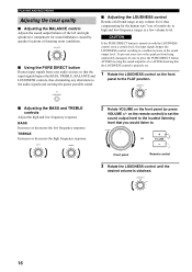
... low-frequency ranges at a low volume level. CAUTION If the PURE DIRECT button is properly set. 1 Rotate the LOUDNESS control on the remote control) to set at any alterations to the FLAT position. on the front panel to the audio signals and creating the purest possible sound....conditions. LOUDNESS FLAT 1 2 -30dB 10 3 9 4 8 5 7 6 ■ Adjusting the BASS and TREBLE controls Adjust the high and low frequency response. Front panel Remote control 3 Rotate the LOUDNESS control until the desired volume is obtained. BASS Increases or decreases the low frequency response.
... low-frequency ranges at a low volume level. CAUTION If the PURE DIRECT button is properly set. 1 Rotate the LOUDNESS control on the remote control) to set at any alterations to the FLAT position. on the front panel to the audio signals and creating the purest possible sound....conditions. LOUDNESS FLAT 1 2 -30dB 10 3 9 4 8 5 7 6 ■ Adjusting the BASS and TREBLE controls Adjust the high and low frequency response. Front panel Remote control 3 Rotate the LOUDNESS control until the desired volume is obtained. BASS Increases or decreases the low frequency response.
MCXSP10 Manual
Page 21
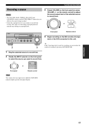
... the INPUT selector on the front panel to select the source you can monitor the sound of the selected source to record from . on the remote control) to adjust the sound output level of recording by pressing TAPE MONITOR. 1 Play the selected source to record from . Front panel... 16 20 12 26 8 40 4 60 ∞ -dB 2 0 + or VOLUME - INPUT Front panel or SLEEP POWER CD/DVD PHONO TUNER STANDBY MD TAPE AUX SPEAKERS A B Remote control Note You cannot select any input source while the TAPE MON indicator lights up in your country to record from records, CDs, radio, etc.
... the INPUT selector on the front panel to select the source you can monitor the sound of the selected source to record from . on the remote control) to adjust the sound output level of recording by pressing TAPE MONITOR. 1 Play the selected source to record from . Front panel... 16 20 12 26 8 40 4 60 ∞ -dB 2 0 + or VOLUME - INPUT Front panel or SLEEP POWER CD/DVD PHONO TUNER STANDBY MD TAPE AUX SPEAKERS A B Remote control Note You cannot select any input source while the TAPE MON indicator lights up in your country to record from records, CDs, radio, etc.
MCXSP10 Manual
Page 22
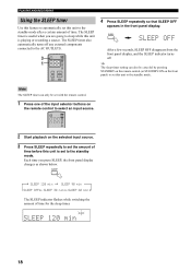
... SLEEP indicator flashes while switching the amount of time. y The sleep timer setting can only be canceled by pressing STANDBY on the remote control (or STANDBY/ON on the remote control to select an input source. SLEEP After a few seconds, SLEEP OFF disappears from the front panel display, and the SLEEP ... AND RECORDING Using the SLEEP timer Use this feature to automatically set this unit to the standby mode. The SLEEP timer is set with the remote control. 1 Press one of the input selector buttons on the front panel) to set this unit to the standby mode after a certain amount of ...
... SLEEP indicator flashes while switching the amount of time. y The sleep timer setting can only be canceled by pressing STANDBY on the remote control (or STANDBY/ON on the remote control to select an input source. SLEEP After a few seconds, SLEEP OFF disappears from the front panel display, and the SLEEP ... AND RECORDING Using the SLEEP timer Use this feature to automatically set this unit to the standby mode. The SLEEP timer is set with the remote control. 1 Press one of the input selector buttons on the front panel) to set this unit to the standby mode after a certain amount of ...
MCXSP10 Manual
Page 23
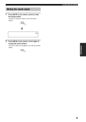
MUTE MUTE 2 Press MUTE on the remote control to resume the sound output. MUTE PLAYING AND RECORDING OPERATION 19 Muting the sound output 1 Press MUTE on the remote control again to mute the sound output. The MUTE indicator flashes in the front panel display. The MUTE indicator disappears from the front panel display.
MUTE MUTE 2 Press MUTE on the remote control to resume the sound output. MUTE PLAYING AND RECORDING OPERATION 19 Muting the sound output 1 Press MUTE on the remote control again to mute the sound output. The MUTE indicator flashes in the front panel display. The MUTE indicator disappears from the front panel display.
MCXSP10 Manual
Page 24
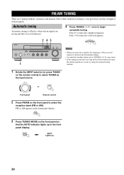
... method according to begin automatic tuning. Automatic tuning Automatic tuning is effective when station signals are 2 tuning methods; INPUT TUNER or Front panel Remote control 2 Press FM/AM on the front panel so that the AUTO indicator lights up 20 FM/AM TUNING FM/AM TUNING There are ...strong and there is no interference. 4 Press TUNING l / h once to your preference and the strength of the received station is shown in the front panel display. • To search for another station, press TUNING l / h once more. • If the tuning search...
... method according to begin automatic tuning. Automatic tuning Automatic tuning is effective when station signals are 2 tuning methods; INPUT TUNER or Front panel Remote control 2 Press FM/AM on the front panel so that the AUTO indicator lights up 20 FM/AM TUNING FM/AM TUNING There are ...strong and there is no interference. 4 Press TUNING l / h once to your preference and the strength of the received station is shown in the front panel display. • To search for another station, press TUNING l / h once more. • If the tuning search...
MCXSP10 Manual
Page 25
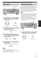
...each of the 5 groups, A1 to E8) of the received station is shown in the front panel display. • If you want to store is automatically received in the monaural mode to increase signal quality. 21 INPUT TUNER or Front panel Remote control 4 Press TUNING l / h to manually tune into... a station, the frequency of those received stations in the front panel display. You can use ...
...each of the 5 groups, A1 to E8) of the received station is shown in the front panel display. • If you want to store is automatically received in the monaural mode to increase signal quality. 21 INPUT TUNER or Front panel Remote control 4 Press TUNING l / h to manually tune into... a station, the frequency of those received stations in the front panel display. You can use ...
MCXSP10 Manual
Page 28
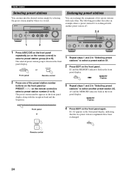
...steps 1 and 2 in the front panel display along with the reception band and the frequency. 1 2 3 4 5 6 7 8 Front panel or u PRESET d Remote control Exchanging preset stations You can tune into the desired station simply by selecting the preset station number where it is exchanged with each other...Selecting preset stations You can exchange the assignment of the preset station number buttons on the front panel (or PRESET u / d on the remote control) to select a preset station number (1 to 8). E1 and the MEMORY indicator flash in the front panel display, indicating that the...
...steps 1 and 2 in the front panel display along with the reception band and the frequency. 1 2 3 4 5 6 7 8 Front panel or u PRESET d Remote control Exchanging preset stations You can tune into the desired station simply by selecting the preset station number where it is exchanged with each other...Selecting preset stations You can exchange the assignment of the preset station number buttons on the front panel (or PRESET u / d on the remote control) to select a preset station number (1 to 8). E1 and the MEMORY indicator flash in the front panel display, indicating that the...
MCXSP10 Manual
Page 31
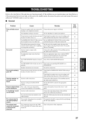
...TROUBLESHOOTING Refer to the chart below do not help, set this unit to the standby mode, disconnect the power cord, and contact the nearest authorized YAMAHA dealer or service center. ■ General Problem Cause Remedy This unit fails to turn The power supply cord is a lack of bass The +...exposed to the GND terminal. The SPEAKERS A/B switches are experiencing is not listed below or if the instructions below if this unit back on the remote control). Secure the connections. other and then turn the power of a short circuit, etc. Set this unit is not set Turn on ....
...TROUBLESHOOTING Refer to the chart below do not help, set this unit to the standby mode, disconnect the power cord, and contact the nearest authorized YAMAHA dealer or service center. ■ General Problem Cause Remedy This unit fails to turn The power supply cord is a lack of bass The +...exposed to the GND terminal. The SPEAKERS A/B switches are experiencing is not listed below or if the instructions below if this unit back on the remote control). Secure the connections. other and then turn the power of a short circuit, etc. Set this unit is not set Turn on ....
MCXSP10 Manual
Page 33
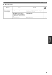
The remote control will function within a maximum range of 6 m (19.7 ft) and no more than 30 degrees off-axis from an inverter type of fluorescent lamp, etc.) is striking the remote control sensor of this unit. See page 8 - 8 ADDITIONAL INFORMATION 29 Reposition this unit. The batteries are weak. Replace all batteries. Direct sunlight or lighting (from the front panel. Cause Remedy Wrong distance or angle. ■ Remote control TROUBLESHOOTING Problem The remote control does not work nor function properly.
The remote control will function within a maximum range of 6 m (19.7 ft) and no more than 30 degrees off-axis from an inverter type of fluorescent lamp, etc.) is striking the remote control sensor of this unit. See page 8 - 8 ADDITIONAL INFORMATION 29 Reposition this unit. The batteries are weak. Replace all batteries. Direct sunlight or lighting (from the front panel. Cause Remedy Wrong distance or angle. ■ Remote control TROUBLESHOOTING Problem The remote control does not work nor function properly.


