

Owner's Manual
Page 2
... is being affected by Yamaha-Kemble Music (U.K.) Ltd. (2 wires) FCC INFORMATION (U.S.A.) 1. If these requirements provides a reasonable level of America or its subsidiaries. * This applies only to distribute this manual, meets FCC requirements. Making sure that are coloured in accordance with the letter L or coloured RED. Cable/s supplied with the requirements listed in all installation instructions. Compliance with these corrective...
... is being affected by Yamaha-Kemble Music (U.K.) Ltd. (2 wires) FCC INFORMATION (U.S.A.) 1. If these requirements provides a reasonable level of America or its subsidiaries. * This applies only to distribute this manual, meets FCC requirements. Making sure that are coloured in accordance with the letter L or coloured RED. Cable/s supplied with the requirements listed in all installation instructions. Compliance with these corrective...
Owner's Manual
Page 3
... in noise, both in the device itself and not the cord. These precautions include, but are not limited to disassemble the internal parts or modify them in a car during use of time at a high or uncomfortable volume level, since this happens, turn on or off the power immediately and unplug the power cord from the outlet. • Avoid setting all volume levels to the internal components...
... in noise, both in the device itself and not the cord. These precautions include, but are not limited to disassemble the internal parts or modify them in a car during use of time at a high or uncomfortable volume level, since this happens, turn on or off the power immediately and unplug the power cord from the outlet. • Avoid setting all volume levels to the internal components...
Owner's Manual
Page 4
... normal. Yamaha cannot be the same in ambient temperatures higher than personal use . Since specifications, equipment or options may exceed 50°C in every locale, please check with your Yamaha dealer. 4 MG124CX/MG124C Owner's Manual When you unplug the power cord from the wall AC outlet. XLR-type connectors are wired as switches, volume controls, and connectors, deteriorates over time.
... normal. Yamaha cannot be the same in ambient temperatures higher than personal use . Since specifications, equipment or options may exceed 50°C in every locale, please check with your Yamaha dealer. 4 MG124CX/MG124C Owner's Manual When you unplug the power cord from the wall AC outlet. XLR-type connectors are wired as switches, volume controls, and connectors, deteriorates over time.
Owner's Manual
Page 5
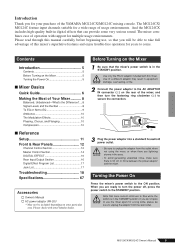
... Power On 5 ■ Mixer Basics Quick Guide 6 Making the Most of Your Mixer........... 8 Balanced, Unbalanced-What's the Difference?.... 8 Signal Levels and the Decibel 8 To EQ or Not to EQ 9 Ambience 10 The Modulation Effects 10 Phasing, Chorus, and Flanging 10 Compression 10 ■ Reference Setup 11 Front & Rear Panels 12 Channel Control Section 12 Master Control Section 14 DIGITAL EFFECT 16 Rear Input/Output Section 16 Digital Effect Program List 17 Jack List 17 Troubleshooting 18 Specifications 67 Accessories Owner's Manual...
... Power On 5 ■ Mixer Basics Quick Guide 6 Making the Most of Your Mixer........... 8 Balanced, Unbalanced-What's the Difference?.... 8 Signal Levels and the Decibel 8 To EQ or Not to EQ 9 Ambience 10 The Modulation Effects 10 Phasing, Chorus, and Flanging 10 Compression 10 ■ Reference Setup 11 Front & Rear Panels 12 Channel Control Section 12 Master Control Section 14 DIGITAL EFFECT 16 Rear Input/Output Section 16 Digital Effect Program List 17 Jack List 17 Troubleshooting 18 Specifications 67 Accessories Owner's Manual...
Owner's Manual
Page 6
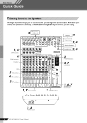
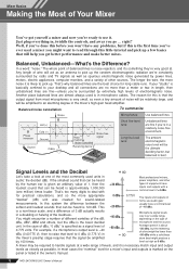
Mixer Basics Quick Guide Mixer Basics Getting Sound to the input devices you are using. 2 Microphones, instruments 1, 4 GAIN controls 4 PEAK indicators Equalizer PAN 5 ON switches 4 PFL switches 5 ST switches ON ON ON ON ON ON ON ON ON 1, 7 Channel faders 1 GROUP 1-2 fader 2 Speakers Power Amp 2, 4 Monitor Speakers 2, 4 Headphones 3 PHANTOM switch 4, 7 Level meter 1, 6, 7 STEREO OUT Master fader 1, 3 POWER switch 6 MG124CX/MG124C Owner's Manual Note that operations and procedures will vary somewhat according to the Speakers We begin by connecting a pair of speakers and ...
Mixer Basics Quick Guide Mixer Basics Getting Sound to the input devices you are using. 2 Microphones, instruments 1, 4 GAIN controls 4 PEAK indicators Equalizer PAN 5 ON switches 4 PFL switches 5 ST switches ON ON ON ON ON ON ON ON ON 1, 7 Channel faders 1 GROUP 1-2 fader 2 Speakers Power Amp 2, 4 Monitor Speakers 2, 4 Headphones 3 PHANTOM switch 4, 7 Level meter 1, 6, 7 STEREO OUT Master fader 1, 3 POWER switch 6 MG124CX/MG124C Owner's Manual Note that operations and procedures will vary somewhat according to the Speakers We begin by connecting a pair of speakers and ...
Owner's Manual
Page 7
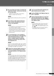
... the PHONES jack outputs the pre-fader signal from all the way down. * STEREO OUT Master Fader, Channel Fader, GROUP 1-2 Fader, Gain Control, etc. Connecting these instruments directly to the MG mixer may result in degraded sound and noise. 3 To avoid damage to their t positions. 2 Turn off ( ) and the MONITOR switch to STEREO ( ). * If the PEAK indicator lights frequently, lower the Channel faders a little to create the desired initial balance, then adjust the overall volume using microphones that the LEVEL meter indication...
... the PHONES jack outputs the pre-fader signal from all the way down. * STEREO OUT Master Fader, Channel Fader, GROUP 1-2 Fader, Gain Control, etc. Connecting these instruments directly to the MG mixer may result in degraded sound and noise. 3 To avoid damage to their t positions. 2 Turn off ( ) and the MONITOR switch to STEREO ( ). * If the PEAK indicator lights frequently, lower the Channel faders a little to create the desired initial balance, then adjust the overall volume using microphones that the LEVEL meter indication...
Owner's Manual
Page 8
... controls, and away you 're surrounded by 100 times. -40 dBu -60 dBu Microphone signal levels vary over a wide range depending on the type of -10 dBu. If your "studio" is best. This + 20 dBu 0 dBu -20 dBu 0.775 V Most professional mixers, power amplifiers, and other sources. Phase inversion Hot (+) Cold (-) Ground Source Cable Phase inversion Noise cancelled Receiving device Noise-free signal Short line-level runs: Long line-level...
... controls, and away you 're surrounded by 100 times. -40 dBu -60 dBu Microphone signal levels vary over a wide range depending on the type of -10 dBu. If your "studio" is best. This + 20 dBu 0 dBu -20 dBu 0.775 V Most professional mixers, power amplifiers, and other sources. Phase inversion Hot (+) Cold (-) Ground Source Cable Phase inversion Noise cancelled Receiving device Noise-free signal Short line-level runs: Long line-level...
Owner's Manual
Page 9
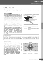
... channels all the way down without compromising the character of a standard pitchfork used to tune guitars and other instruments in the way the mix sounds more effectively. Average conversation occurs in the range from a bit of low-frequency roll-off the high end to EQ In general: less is better. Boost with too much as musical sound, but use...
... channels all the way down without compromising the character of a standard pitchfork used to tune guitars and other instruments in the way the mix sounds more effectively. Average conversation occurs in the range from a bit of low-frequency roll-off the high end to EQ In general: less is better. Boost with too much as musical sound, but use...
Owner's Manual
Page 10
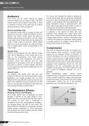
... the direct signal. The Modulation Effects: Phasing, Chorus, and Flanging All of these effects work on basically the same principle: a portion of music will have different "reverb tone" due to differences in the reverb time of delay time and feedback used-flanging uses longer delay times than chorus, whereas chorus generally uses a more than this causes the shimmering sound we hear. The MG compressor makes achieving great sound much reverb, particularly...
... the direct signal. The Modulation Effects: Phasing, Chorus, and Flanging All of these effects work on basically the same principle: a portion of music will have different "reverb tone" due to differences in the reverb time of delay time and feedback used-flanging uses longer delay times than chorus, whereas chorus generally uses a more than this causes the shimmering sound we hear. The MG compressor makes achieving great sound much reverb, particularly...
Owner's Manual
Page 11
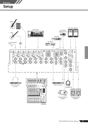
Reference Setup Reference Guitar Bass Microphone DI Synthesizer Powered Speakers Foot Switch (YAMAHA FC5) Recorder CD Player Effect Processor (exciter) Effect Processor Headphones MG124CX Powered Monitor Speaker Powered Monitor Speakers MG124CX/MG124C Owner's Manual 11
Reference Setup Reference Guitar Bass Microphone DI Synthesizer Powered Speakers Foot Switch (YAMAHA FC5) Recorder CD Player Effect Processor (exciter) Effect Processor Headphones MG124CX Powered Monitor Speaker Powered Monitor Speakers MG124CX/MG124C Owner's Manual 11
Owner's Manual
Page 12
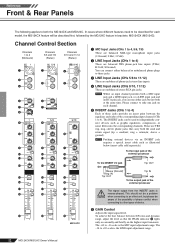
... signal output from the INSERT jacks is the MIC input adjustment range. The INSERT jacks can be described first, followed by the MG124C feature in ; You can use either balanced or unbalanced phone plugs to -16 scale is reverse-phased. NOTE Patching external devices via an INSERT jack requires a special insert cable such as graphic equalizers, compressors, or noise filters into the corresponding channels. To the input jack of device. 6 GAIN Control Adjusts the input signal level...
... signal output from the INSERT jacks is the MIC input adjustment range. The INSERT jacks can be described first, followed by the MG124C feature in ; You can use either balanced or unbalanced phone plugs to -16 scale is reverse-phased. NOTE Patching external devices via an INSERT jack requires a special insert cable such as graphic equalizers, compressors, or noise filters into the corresponding channels. To the input jack of device. 6 GAIN Control Adjusts the input signal level...
Owner's Manual
Page 13
... & Rear Panels 7 Switch (High Pass Filter) This switch toggles the HPF on . D PAN Control (1 to the Group 2 bus or the Stereo R bus. signals input to the R input (even channel) go to the Group 1 bus or to the right the compression ratio increases while the output gain is received via the MIC jack or L (MONO) input only, and as a BAL control when input is automatically adjusted accordingly. When the switch is on ( ). NOTE To send the signal to minimize noise...
... & Rear Panels 7 Switch (High Pass Filter) This switch toggles the HPF on . D PAN Control (1 to the Group 2 bus or the Stereo R bus. signals input to the R input (even channel) go to the Group 1 bus or to the right the compression ratio increases while the output gain is received via the MIC jack or L (MONO) input only, and as a BAL control when input is automatically adjusted accordingly. When the switch is on ( ). NOTE To send the signal to minimize noise...
Owner's Manual
Page 14
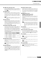
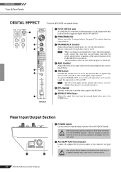
... noise. 1 2TR IN Jacks These RCA pin jacks can be used to record mixer's stereo output while using the 2TR IN control in the Master Control section. 2 REC OUT (L, R) Jacks These RCA pin jacks can be used to both the L and R jacks. 4 SEND Jacks • AUX (AUX1) This is an impedance balanced* phone-jack type output. NOTE The mixer's STEREO OUT Master Fader has no affect on the input channels. 14 MG124CX/MG124C Owner's Manual This jack outputs the signals from an external effect device (reverb, delay...
... noise. 1 2TR IN Jacks These RCA pin jacks can be used to record mixer's stereo output while using the 2TR IN control in the Master Control section. 2 REC OUT (L, R) Jacks These RCA pin jacks can be used to both the L and R jacks. 4 SEND Jacks • AUX (AUX1) This is an impedance balanced* phone-jack type output. NOTE The mixer's STEREO OUT Master Fader has no affect on the input channels. 14 MG124CX/MG124C Owner's Manual This jack outputs the signals from an external effect device (reverb, delay...
Owner's Manual
Page 15
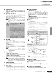
... mixer sends the same signal to the nominal output level. E 2TR IN • 2TR IN Switch If this stereo phone jack. F GROUP 1-2 Fader Adjusts the signal level sent to Stereo R. MG124CX/MG124C Owner's Manual 15 The PHONES jack outputs the same signal as the MONITOR OUT jacks. 9 PHANTOM +48 V Switch This switch toggles phantom power on ( ), then only the PFL output from the EFFECT bus to the C-R OUT jacks, PHONES jacks, and level meter. When the switch is set to STEREO ( ), the STEREO L/R bus signals are using one or more phantom-powered condenser microphones...
... mixer sends the same signal to the nominal output level. E 2TR IN • 2TR IN Switch If this stereo phone jack. F GROUP 1-2 Fader Adjusts the signal level sent to Stereo R. MG124CX/MG124C Owner's Manual 15 The PHONES jack outputs the same signal as the MONITOR OUT jacks. 9 PHANTOM +48 V Switch This switch toggles phantom power on ( ), then only the PFL output from the EFFECT bus to the C-R OUT jacks, PHONES jacks, and level meter. When the switch is set to STEREO ( ), the STEREO L/R bus signals are using one or more phantom-powered condenser microphones...
Owner's Manual
Page 16
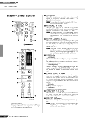
... internal digital effect unit to the AUX bus. 5 ON Switch Switches the internal effect on . Use only the PA-20 adaptor included with each effect type is turned on or off . 4 AUX Control Adjusts the level of 1 2 a different adaptor may result in the STANDBY position. Reference Front & Rear Panels DIGITAL EFFECT *Only the MG124CX has digital effects. 1 2 3 4 5 ON 6 7 MG124CX 1 FOOT SWITCH Jack A YAMAHA FC5 foot switch (sold separately) can be connected to this switch to turn the mixer's power ON or to STANDBY mode...
... internal digital effect unit to the AUX bus. 5 ON Switch Switches the internal effect on . Use only the PA-20 adaptor included with each effect type is turned on or off . 4 AUX Control Adjusts the level of 1 2 a different adaptor may result in the STANDBY position. Reference Front & Rear Panels DIGITAL EFFECT *Only the MG124CX has digital effects. 1 2 3 4 5 ON 6 7 MG124CX 1 FOOT SWITCH Jack A YAMAHA FC5 foot switch (sold separately) can be connected to this switch to turn the mixer's power ON or to STANDBY mode...
Owner's Manual
Page 17
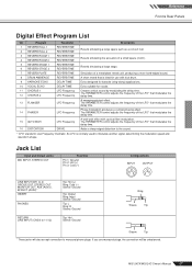
... pitched effect. Jack List Input and Output Jacks MIC INPUT, STEREO OUT Polarities Pin 1: Ground Pin 2: Hot (+) Pin 3: Cold (-) Configurations INPUT OUTPUT LINE INPUT(CH1 to 4) GROUP OUT, STEREO OUT, MONITOR OUT, AUX (AUX1), EFFECT (AUX2)* INSERT PHONES RETURN LINE INPUT (CH5/6 to monaural phone plugs. If you use with cyclical filter modulation. The PARAMETER control adjusts the frequency of the LFO* that modulates the delay time. 14 PHASER LFO Frequency Phase modulation produces a cyclical phasing effect. An...
... pitched effect. Jack List Input and Output Jacks MIC INPUT, STEREO OUT Polarities Pin 1: Ground Pin 2: Hot (+) Pin 3: Cold (-) Configurations INPUT OUTPUT LINE INPUT(CH1 to 4) GROUP OUT, STEREO OUT, MONITOR OUT, AUX (AUX1), EFFECT (AUX2)* INSERT PHONES RETURN LINE INPUT (CH5/6 to monaural phone plugs. If you use with cyclical filter modulation. The PARAMETER control adjusts the frequency of the LFO* that modulates the delay time. 14 PHASER LFO Frequency Phase modulation produces a cyclical phasing effect. An...
Owner's Manual
Page 18
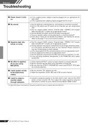
... output a monitor signal through speakers. ❑ Connect a powered speaker to only one channel? Reference Troubleshooting ■ Power doesn't come on. ❑ Is the supplied power adaptor properly plugged into an appropriate AC wall outlet? ❑ Is the supplied power adaptor properly plugged into the mixer? ■ No sound. ❑ Are microphones, external devices, and speakers connected correctly? ❑ Are the ON switch and ST switch of the channels you are using turned ON? ❑ Are the channel GAIN controls, Channel fader, STEREO OUT master fader...
... output a monitor signal through speakers. ❑ Connect a powered speaker to only one channel? Reference Troubleshooting ■ Power doesn't come on. ❑ Is the supplied power adaptor properly plugged into an appropriate AC wall outlet? ❑ Is the supplied power adaptor properly plugged into the mixer? ■ No sound. ❑ Are microphones, external devices, and speakers connected correctly? ❑ Are the ON switch and ST switch of the channels you are using turned ON? ❑ Are the channel GAIN controls, Channel fader, STEREO OUT master fader...
Owner's Manual
Page 19
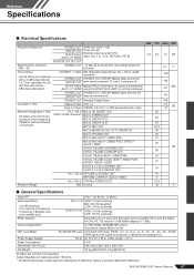
... attenuation. Internal Digital Effect* LED Level Meter 16 PROGRAM, PARAMETER control Foot Switch (Digital Effect On/Off) Pre MONITOR Level 2x12 points LED meter (PEAK, +10, +6, +3, 0, -3, -6, -10, -15, -20, -25, -30 dB) PEAK lights if the signal level reaches 3 dB below clipping (+17 dBu). equivalent to a 20 kHz filter with a 6 dB/octave filter @ 12.7 kHz; Power Supply Adaptor Power Consumption PA-20 AC 35 VCT, 0.94 A, Cable Length = 3.6 m 30 W Dimensions...
... attenuation. Internal Digital Effect* LED Level Meter 16 PROGRAM, PARAMETER control Foot Switch (Digital Effect On/Off) Pre MONITOR Level 2x12 points LED meter (PEAK, +10, +6, +3, 0, -3, -6, -10, -15, -20, -25, -30 dB) PEAK lights if the signal level reaches 3 dB below clipping (+17 dBu). equivalent to a 20 kHz filter with a 6 dB/octave filter @ 12.7 kHz; Power Supply Adaptor Power Consumption PA-20 AC 35 VCT, 0.94 A, Cable Length = 3.6 m 30 W Dimensions...
Owner's Manual
Page 20
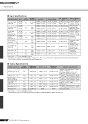
...]) RCA pin jack Phone jack (impedance balanced [Tip = HOT, Ring = COLD, Sleeve = GND]) Stereo phone jack Where 0 dBu = 0.775 Vrms and 0 dBV= 1 Vrms * The MG124CX feature is set to the maximum level. (All faders and level controls are at their maximum position.) ■ Output Specifications Output Connectors STEREO OUT (L, R) GROUP OUT (1, 2) EFFECT/AUX (AUX1, 2*) SEND CH INSERT OUT (CHs 1-4) REC OUT (L, R) MONITOR OUT (L, R) PHONES OUT Output Impedance 75...
...]) RCA pin jack Phone jack (impedance balanced [Tip = HOT, Ring = COLD, Sleeve = GND]) Stereo phone jack Where 0 dBu = 0.775 Vrms and 0 dBV= 1 Vrms * The MG124CX feature is set to the maximum level. (All faders and level controls are at their maximum position.) ■ Output Specifications Output Connectors STEREO OUT (L, R) GROUP OUT (1, 2) EFFECT/AUX (AUX1, 2*) SEND CH INSERT OUT (CHs 1-4) REC OUT (L, R) MONITOR OUT (L, R) PHONES OUT Output Impedance 75...
Owner's Manual
Page 22
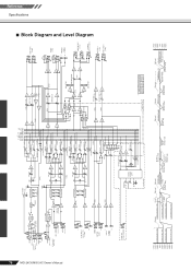
... OUT [-10dBV] R [-7.8dBu] L MONITOR OUT [+4dBu] R PHONES [3mW @ 40ohms] AUX SEND *1 [+4dBu] EFFECT SEND *1 [+4dBu] MONITOR MIX *1 MODEL FUNCTION NAME MG124CX AUX EFFECT MG124C AUX1 AUX2 Clip Level Clip Level Clip Level Clip Level AUX SEND *1 [+4dBu] GROUP OUT [+4dBu] AUX SEND *1 [Nominal:-6dB] GROUP Fader [Nominal:-10dB] STEREO Master [Nominal:-10dB] STEREO OUT [+4dBu] MONITOR OUT [+4dBu] REC OUT [-7.8dBu] PHONES [3mW @ 40ohms] MONITOR/PHONES [Nominal:-16dB] +30dBu +20dBu +10dBu 0dBu -10dBu -20dBu -30dBu Reference Specifications ■ Block Diagram and Level Diagram
... OUT [-10dBV] R [-7.8dBu] L MONITOR OUT [+4dBu] R PHONES [3mW @ 40ohms] AUX SEND *1 [+4dBu] EFFECT SEND *1 [+4dBu] MONITOR MIX *1 MODEL FUNCTION NAME MG124CX AUX EFFECT MG124C AUX1 AUX2 Clip Level Clip Level Clip Level Clip Level AUX SEND *1 [+4dBu] GROUP OUT [+4dBu] AUX SEND *1 [Nominal:-6dB] GROUP Fader [Nominal:-10dB] STEREO Master [Nominal:-10dB] STEREO OUT [+4dBu] MONITOR OUT [+4dBu] REC OUT [-7.8dBu] PHONES [3mW @ 40ohms] MONITOR/PHONES [Nominal:-16dB] +30dBu +20dBu +10dBu 0dBu -10dBu -20dBu -30dBu Reference Specifications ■ Block Diagram and Level Diagram


