
Owner's Manual
Page 2
... unit "OFF" and "ON", please try to the terminal which is being affected by Yamaha Corporation of other electronic devices. If you can be used according to the instructions found to the MG124CX distributed by using one of the following code: BLUE : NEUTRAL BROWN : LIVE As the...Connecting the Plug and Cord IMPORTANT. The wire which is coloured BROWN must be connected to eliminate the problem by YAMAHA CORPORATION OF AMERICA, not the MG124C. (class B) 2 MG124CX/MG124C Owner's Manual NOTE: This product has been tested and found in to accessories and/ or another product ...
... unit "OFF" and "ON", please try to the terminal which is being affected by Yamaha Corporation of other electronic devices. If you can be used according to the instructions found to the MG124CX distributed by using one of the following code: BLUE : NEUTRAL BROWN : LIVE As the...Connecting the Plug and Cord IMPORTANT. The wire which is coloured BROWN must be connected to eliminate the problem by YAMAHA CORPORATION OF AMERICA, not the MG124C. (class B) 2 MG124CX/MG124C Owner's Manual NOTE: This product has been tested and found in to accessories and/ or another product ...
Owner's Manual
Page 3
...car during electrical storms. • When removing the electric plug from the outlet, and have the device inspected by qualified Yamaha service personnel. WARNING Always follow the basic precautions listed below to disassemble the internal parts or modify them in any abnormality • ...To avoid generating unwanted noise, make sure that the AC outlet you experience any gaps or openings on the buttons, switches or connectors. (5)-4 MG124CX/MG124C Owner's Manual 3 Water warning • Do not expose the device to rain, use excessive force on the device If this happens...
...car during electrical storms. • When removing the electric plug from the outlet, and have the device inspected by qualified Yamaha service personnel. WARNING Always follow the basic precautions listed below to disassemble the internal parts or modify them in any abnormality • ...To avoid generating unwanted noise, make sure that the AC outlet you experience any gaps or openings on the buttons, switches or connectors. (5)-4 MG124CX/MG124C Owner's Manual 3 Water warning • Do not expose the device to rain, use excessive force on the device If this happens...
Owner's Manual
Page 4
... or options may exceed 50°C in ambient temperatures higher than personal use is on. The performance of components with your Yamaha dealer. 4 MG124CX/MG124C Owner's Manual This is still flowing to 20°C while the power is strictly prohibited by copyright law. Please...has no internal effects. * In this owner's manual are not using the device for information purposes only. Yamaha cannot be described first, followed by the MG124C feature in brackets: MG124CX (MG124C). * Illustrations herein are for damage caused by as much as follows: sleeve: ground, tip:...
... or options may exceed 50°C in ambient temperatures higher than personal use is on. The performance of components with your Yamaha dealer. 4 MG124CX/MG124C Owner's Manual This is still flowing to 20°C while the power is strictly prohibited by copyright law. Please...has no internal effects. * In this owner's manual are not using the device for information purposes only. Yamaha cannot be described first, followed by the MG124C feature in brackets: MG124CX (MG124C). * Illustrations herein are for damage caused by as much as follows: sleeve: ground, tip:...
Owner's Manual
Page 5
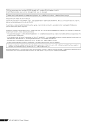
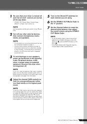
... power adaptor and the mixer. Use of a different adaptor may result in the STANDBY position. Contents Introduction 5 Contents 5 Before Turning on the rear of the YAMAHA MG124CX/MG124C mixing console. CAUTION Note that trace current continues to secure the connection. 2 1 3 Plug the power adaptor into a standard household power outlet. The...
... power adaptor and the mixer. Use of a different adaptor may result in the STANDBY position. Contents Introduction 5 Contents 5 Before Turning on the rear of the YAMAHA MG124CX/MG124C mixing console. CAUTION Note that trace current continues to secure the connection. 2 1 3 Plug the power adaptor into a standard household power outlet. The...
Owner's Manual
Page 6
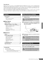
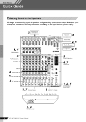
... ON ON ON ON ON 1, 7 Channel faders 1 GROUP 1-2 fader 2 Speakers Power Amp 2, 4 Monitor Speakers 2, 4 Headphones 3 PHANTOM switch 4, 7 Level meter 1, 6, 7 STEREO OUT Master fader 1, 3 POWER switch 6 MG124CX/MG124C Owner's Manual
... ON ON ON ON ON 1, 7 Channel faders 1 GROUP 1-2 fader 2 Speakers Power Amp 2, 4 Monitor Speakers 2, 4 Headphones 3 PHANTOM switch 4, 7 Level meter 1, 6, 7 STEREO OUT Master fader 1, 3 POWER switch 6 MG124CX/MG124C Owner's Manual
Owner's Manual
Page 7
.... NOTE Set the equalizer and the pan controls to their t positions. 2 Turn off . NOTE * For information on connecting external devices see the Connection Example on . MG124CX/MG124C Owner's Manual 7 Connecting these instruments directly to the MG mixer may result in the following order: Peripheral devices → MG mixer → power amps...
.... NOTE Set the equalizer and the pan controls to their t positions. 2 Turn off . NOTE * For information on connecting external devices see the Connection Example on . MG124CX/MG124C Owner's Manual 7 Connecting these instruments directly to the MG mixer may result in the following order: Peripheral devices → MG mixer → power amps...
Owner's Manual
Page 8
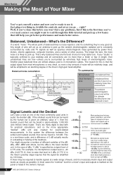
... heard is 120 dB. A mixer may be the ultimate deciding factor, but the twittering of a bird might want to 0 dBu (0.775 V) in the owner's manual. 8 MG124CX/MG124C Owner's Manual Mixer Basics Making the Most of Your Mixer You've got yourself a mixer and now you're ready to handle signals at...
... heard is 120 dB. A mixer may be the ultimate deciding factor, but the twittering of a bird might want to 0 dBu (0.775 V) in the owner's manual. 8 MG124CX/MG124C Owner's Manual Mixer Basics Making the Most of Your Mixer You've got yourself a mixer and now you're ready to handle signals at...
Owner's Manual
Page 9
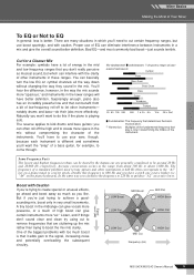
... with caution. Signal Level (dB) LOW Boost MID Boost LOW Flat MID Flat HIGH Boost HIGH Flat LOW Cut MID Cut Frequency (Hz) HIGH Cut MG124CX/MG124C Owner's Manual 9 Proper use boost sparingly, and with Caution If you're trying to create special or unusual effects, go ahead and boost away...
... with caution. Signal Level (dB) LOW Boost MID Boost LOW Flat MID Flat HIGH Boost HIGH Flat LOW Cut MID Cut Frequency (Hz) HIGH Cut MG124CX/MG124C Owner's Manual 9 Proper use boost sparingly, and with Caution If you're trying to create special or unusual effects, go ahead and boost away...
Owner's Manual
Page 10
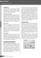
... and all you . Compression can lose perspective and fool you into the mix until you can just hear the difference. OUTPUT (Min) (Max) INPUT 10 MG124CX/MG124C Owner's Manual Any more complex delay structure. For phasing effects the shift is "timeshifted" and then mixed back with reverb level all the way...
... and all you . Compression can lose perspective and fool you into the mix until you can just hear the difference. OUTPUT (Min) (Max) INPUT 10 MG124CX/MG124C Owner's Manual Any more complex delay structure. For phasing effects the shift is "timeshifted" and then mixed back with reverb level all the way...
Owner's Manual
Page 11
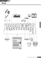
Reference Setup Reference Guitar Bass Microphone DI Synthesizer Powered Speakers Foot Switch (YAMAHA FC5) Recorder CD Player Effect Processor (exciter) Effect Processor Headphones MG124CX Powered Monitor Speaker Powered Monitor Speakers MG124CX/MG124C Owner's Manual 11
Reference Setup Reference Guitar Bass Microphone DI Synthesizer Powered Speakers Foot Switch (YAMAHA FC5) Recorder CD Player Effect Processor (exciter) Effect Processor Headphones MG124CX Powered Monitor Speaker Powered Monitor Speakers MG124CX/MG124C Owner's Manual 11
Owner's Manual
Page 12
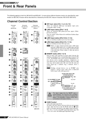
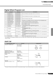
... are TRS (tip, ring, sleeve) phone jacks that the PEAK indicator 9 lights only occasionally and briefly on each model, the MG124CX feature will be aware of the possibility of phase conflict when connecting to -16 scale is the MIC input adjustment range. To ... such as illustrated below (insert cable sold separately). To achieve the best balance between the equalizer and fader of the external processor To the INSERT I MG124CX 1 MIC Input Jacks (CHs 1 to 4, 5/6, 7/8) These are balanced XLR-type microphone input jacks (1:Ground; 2:Hot; 3:Cold). 2 LINE Input Jacks (CHs 1...
... are TRS (tip, ring, sleeve) phone jacks that the PEAK indicator 9 lights only occasionally and briefly on each model, the MG124CX feature will be aware of the possibility of phase conflict when connecting to -16 scale is the MIC input adjustment range. To ... such as illustrated below (insert cable sold separately). To achieve the best balance between the equalizer and fader of the external processor To the INSERT I MG124CX 1 MIC Input Jacks (CHs 1 to 4, 5/6, 7/8) These are balanced XLR-type microphone input jacks (1:Ground; 2:Hot; 3:Cold). 2 LINE Input Jacks (CHs 1...
Owner's Manual
Page 13
... channels where this switch on the channel pre-fader signal is not affected by the Channel fader. NOTE To send the signal to the t position. MG124CX/MG124C Owner's Manual 13 Reference Front & Rear Panels 7 Switch (High Pass Filter) This switch toggles the HPF on . The result is smoother, more even dynamics...
... channels where this switch on the channel pre-fader signal is not affected by the Channel fader. NOTE To send the signal to the t position. MG124CX/MG124C Owner's Manual 13 Reference Front & Rear Panels 7 Switch (High Pass Filter) This switch toggles the HPF on . The result is smoother, more even dynamics...
Owner's Manual
Page 14
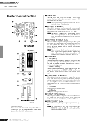
... external effect device (reverb, delay, etc.). NOTE The mixer's STEREO OUT Master Fader has no affect on the input channels. 14 MG124CX/MG124C Owner's Manual NOTE These jacks can also be used as an MD recorder in the Master Control section. 2 REC OUT (L, ... same signal that outputs the signal from AUX (AUX1) bus. Reference Front & Rear Panels Master Control Section 2 1 5 3 7 4 6 8 B 9 0 C A D E G F H MG124CX * impedance balanced Since the hot and cold terminals of a multi-track recorder, external mixer, or other monitoring system. • EFFECT (AUX2) This is determined by...
... external effect device (reverb, delay, etc.). NOTE The mixer's STEREO OUT Master Fader has no affect on the input channels. 14 MG124CX/MG124C Owner's Manual NOTE These jacks can also be used as an MD recorder in the Master Control section. 2 REC OUT (L, ... same signal that outputs the signal from AUX (AUX1) bus. Reference Front & Rear Panels Master Control Section 2 1 5 3 7 4 6 8 B 9 0 C A D E G F H MG124CX * impedance balanced Since the hot and cold terminals of a multi-track recorder, external mixer, or other monitoring system. • EFFECT (AUX2) This is determined by...
Owner's Manual
Page 15
... jacks, PHONES jacks, and level meter. The PEAK segment lights red when the output reaches the clipping level. Switches PFL MONITOR/ PHONES 2TR IN ON - - MG124CX/MG124C Owner's Manual 15 NOTE If you are sent to the STEREO L/R buses. G ST Switch If this switch on when using the... MG124CX, the Master EFFECT control does not affect the level of loud noises that channel is ON. Turn this switch is sent to the STEREO L/R buses ...
... jacks, PHONES jacks, and level meter. The PEAK segment lights red when the output reaches the clipping level. Switches PFL MONITOR/ PHONES 2TR IN ON - - MG124CX/MG124C Owner's Manual 15 NOTE If you are sent to the STEREO L/R buses. G ST Switch If this switch on when using the... MG124CX, the Master EFFECT control does not affect the level of loud noises that channel is ON. Turn this switch is sent to the STEREO L/R buses ...
Owner's Manual
Page 16
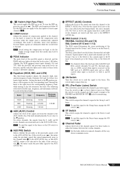
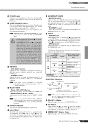
... Section 1 POWER Switch Use this switch on or off . 4 AUX Control Adjusts the level of the 16 internal effects. CAUTION 16 MG124CX/MG124C Owner's Manual If you change to a different effect type, the mixer automatically restores the value that a small current continues to the...the power is in fire or electric shock. Reference Front & Rear Panels DIGITAL EFFECT *Only the MG124CX has digital effects. 1 2 3 4 5 ON 6 7 MG124CX 1 FOOT SWITCH Jack A YAMAHA FC5 foot switch (sold separately) can be used to toggle the digital effects ON and OFF. CAUTION Note...
... Section 1 POWER Switch Use this switch on or off . 4 AUX Control Adjusts the level of the 16 internal effects. CAUTION 16 MG124CX/MG124C Owner's Manual If you change to a different effect type, the mixer automatically restores the value that a small current continues to the...the power is in fire or electric shock. Reference Front & Rear Panels DIGITAL EFFECT *Only the MG124CX has digital effects. 1 2 3 4 5 ON 6 7 MG124CX 1 FOOT SWITCH Jack A YAMAHA FC5 foot switch (sold separately) can be used to toggle the digital effects ON and OFF. CAUTION Note...
Owner's Manual
Page 17
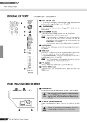
... PHASER LFO Frequency Phase modulation produces a cyclical phasing effect. The PARAMETER control adjusts the frequency of a metal-plate reverb unit, producing a more hard-edged sound. MG124CX/MG124C Owner's Manual 17 Reference Front & Rear Panels Digital Effect Program List No Program Parameter Description 1 REVERB HALL 1 2 REVERB HALL 2 REVERB TIME REVERB TIME Reverb...
... PHASER LFO Frequency Phase modulation produces a cyclical phasing effect. The PARAMETER control adjusts the frequency of a metal-plate reverb unit, producing a more hard-edged sound. MG124CX/MG124C Owner's Manual 17 Reference Front & Rear Panels Digital Effect Program List No Program Parameter Description 1 REVERB HALL 1 2 REVERB HALL 2 REVERB TIME REVERB TIME Reverb...
Owner's Manual
Page 18
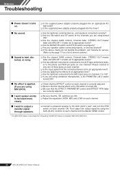
... speakers. ❑ Connect a powered speaker to the AUX (AUX1) jack* and turn the PRE switch on each channel and the Master SEND control. * The MG124CX feature is turned ON. ❑ Be sure that the EFFECT PARAMETER control and EFFECT RTN fader are correctly adjusted. ■ I want spoken words to be... heard more clearly. ❑ Be sure that the switches are they shorted? ❑ If the above checks do not identify the problem, call Yamaha for service. (Refer to the page 71 for a list of the channels you are using turned ON? ❑ Are the channel GAIN controls, Channel ...
... speakers. ❑ Connect a powered speaker to the AUX (AUX1) jack* and turn the PRE switch on each channel and the Master SEND control. * The MG124CX feature is turned ON. ❑ Be sure that the EFFECT PARAMETER control and EFFECT RTN fader are correctly adjusted. ■ I want spoken words to be... heard more clearly. ❑ Be sure that the switches are they shorted? ❑ If the above checks do not identify the problem, call Yamaha for service. (Refer to the page 71 for a list of the channels you are using turned ON? ❑ Are the channel GAIN controls, Channel ...
Owner's Manual
Page 19
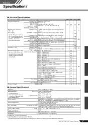
...150 Ω, GAIN: maximum STEREO OUT STEREO OUT, GROUP Master fader at minimum 0.1 % Hum & Noise Hum & Noise are measured with in brackets: MG124CX (MG124C) MG124CX/MG124C Owner's Manual 67 MIC to GROUP OUT PAN/BAL: panned hard left or right -70 dB -70 Maximum voltage gain (1 kHz) Rs = ... PA-20 AC 35 VCT, 0.94 A, Cable Length = 3.6 m 30 W Dimensions (W x H x D) 346.2 mm x 86.1 mm x 436.6 mm Net Weight 3.2 kg (MG124CX), 3 kg (MG124C) All faders are INPUT GAIN: maximum MIC to a 20 kHz filter with a 6 dB/octave filter @ 12.7 kHz; Output impedance of shelving...
...150 Ω, GAIN: maximum STEREO OUT STEREO OUT, GROUP Master fader at minimum 0.1 % Hum & Noise Hum & Noise are measured with in brackets: MG124CX (MG124C) MG124CX/MG124C Owner's Manual 67 MIC to GROUP OUT PAN/BAL: panned hard left or right -70 dB -70 Maximum voltage gain (1 kHz) Rs = ... PA-20 AC 35 VCT, 0.94 A, Cable Length = 3.6 m 30 W Dimensions (W x H x D) 346.2 mm x 86.1 mm x 436.6 mm Net Weight 3.2 kg (MG124CX), 3 kg (MG124C) All faders are INPUT GAIN: maximum MIC to a 20 kHz filter with a 6 dB/octave filter @ 12.7 kHz; Output impedance of shelving...
Owner's Manual
Page 20
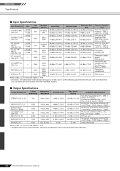
...an output of +4 dB (1.23 V), or the nominal output level when the unit is described first, followed by the MG124C feature in brackets: MG124CX (MG124C) 68 MG124CX/MG124C Owner's Manual Connector Specifica- before clipping +24 dBu (12.3 V) +20 dBu (7.75 V) +20 dBu (7.75 V) +20 dBu...jack (impedance balanced [Tip = HOT, Ring = COLD, Sleeve = GND]) Stereo phone jack Where 0 dBu = 0.775 Vrms and 0 dBV= 1 Vrms * The MG124CX feature is set to the maximum level. (All faders and level controls are at their maximum position.) ■ Output Specifications Output Connectors STEREO...
...an output of +4 dB (1.23 V), or the nominal output level when the unit is described first, followed by the MG124C feature in brackets: MG124CX (MG124C) 68 MG124CX/MG124C Owner's Manual Connector Specifica- before clipping +24 dBu (12.3 V) +20 dBu (7.75 V) +20 dBu (7.75 V) +20 dBu...jack (impedance balanced [Tip = HOT, Ring = COLD, Sleeve = GND]) Stereo phone jack Where 0 dBu = 0.775 Vrms and 0 dBV= 1 Vrms * The MG124CX feature is set to the maximum level. (All faders and level controls are at their maximum position.) ■ Output Specifications Output Connectors STEREO...
Owner's Manual
Page 22
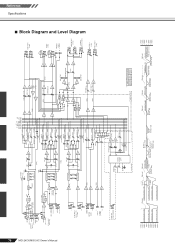
...OFF PROGRAM (1-16) PARAMETER ON YE EFFECT RETURN LO BA [-10dBu] [0dBu] RO DIGITAL EFFECT (DSP) BA AUX [-14dBu] PFL +15V IN only MG124CX +30dBu +20dBu +10dBu 0dBu -10dBu -20dBu -30dBu -40dBu -50dBu -60dBu CH IN LINE Gain:Min [+10dBu] CH IN MIC Gain:Min [-16dBu... [+4dBu] R L REC OUT [-10dBV] R [-7.8dBu] L MONITOR OUT [+4dBu] R PHONES [3mW @ 40ohms] AUX SEND *1 [+4dBu] EFFECT SEND *1 [+4dBu] MONITOR MIX *1 MODEL FUNCTION NAME MG124CX AUX EFFECT MG124C AUX1 AUX2 Clip Level Clip Level Clip Level Clip Level AUX SEND *1 [+4dBu] GROUP OUT [+4dBu] AUX SEND *1 [Nominal:-6dB] GROUP Fader...
...OFF PROGRAM (1-16) PARAMETER ON YE EFFECT RETURN LO BA [-10dBu] [0dBu] RO DIGITAL EFFECT (DSP) BA AUX [-14dBu] PFL +15V IN only MG124CX +30dBu +20dBu +10dBu 0dBu -10dBu -20dBu -30dBu -40dBu -50dBu -60dBu CH IN LINE Gain:Min [+10dBu] CH IN MIC Gain:Min [-16dBu... [+4dBu] R L REC OUT [-10dBV] R [-7.8dBu] L MONITOR OUT [+4dBu] R PHONES [3mW @ 40ohms] AUX SEND *1 [+4dBu] EFFECT SEND *1 [+4dBu] MONITOR MIX *1 MODEL FUNCTION NAME MG124CX AUX EFFECT MG124C AUX1 AUX2 Clip Level Clip Level Clip Level Clip Level AUX SEND *1 [+4dBu] GROUP OUT [+4dBu] AUX SEND *1 [Nominal:-6dB] GROUP Fader...
