
Owner's Manual
Page 5
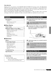
...the STANDBY position. Contents Introduction 5 Contents 5 Before Turning on the Mixer 5 Turning the Power On 5 ■ Mixer Basics Quick Guide 6 Making the Most of the YAMAHA MG124CX/MG124C mixing console. CAUTION • Be sure to unplug the adaptor from the wall outlet. CAUTION Note that you will be able to take full... Section 12 Master Control Section 14 DIGITAL EFFECT 16 Rear Input/Output Section 16 Digital Effect Program List 17 Jack List 17 Troubleshooting 18 Specifications 67 Accessories Owner's Manual AC power adaptor (PA-20)* * May not be included depending on your...
...the STANDBY position. Contents Introduction 5 Contents 5 Before Turning on the Mixer 5 Turning the Power On 5 ■ Mixer Basics Quick Guide 6 Making the Most of the YAMAHA MG124CX/MG124C mixing console. CAUTION • Be sure to unplug the adaptor from the wall outlet. CAUTION Note that you will be able to take full... Section 12 Master Control Section 14 DIGITAL EFFECT 16 Rear Input/Output Section 16 Digital Effect Program List 17 Jack List 17 Troubleshooting 18 Specifications 67 Accessories Owner's Manual AC power adaptor (PA-20)* * May not be included depending on your...
Owner's Manual
Page 20
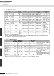
...[Tip = HOT, Ring = COLD, Sleeve = GND]) Stereo phone jack Where 0 dBu = 0.775 Vrms and 0 dBV= 1 Vrms * The MG124CX feature is set to the maximum level. (All faders and level controls are at their maximum position.) ■ Output Specifications Output Connectors STEREO... nominal output level when the unit is described first, followed by the MG124C feature in brackets: MG124CX (MG124C) 68 MG124CX/MG124C Owner's Manual Reference Specifications ■ Input Specifications Input Connectors Gain Input Appropriate Impedance Impedance Sensitivity * Nominal Level Max.
...[Tip = HOT, Ring = COLD, Sleeve = GND]) Stereo phone jack Where 0 dBu = 0.775 Vrms and 0 dBV= 1 Vrms * The MG124CX feature is set to the maximum level. (All faders and level controls are at their maximum position.) ■ Output Specifications Output Connectors STEREO... nominal output level when the unit is described first, followed by the MG124C feature in brackets: MG124CX (MG124C) 68 MG124CX/MG124C Owner's Manual Reference Specifications ■ Input Specifications Input Connectors Gain Input Appropriate Impedance Impedance Sensitivity * Nominal Level Max.
Owner's Manual
Page 22
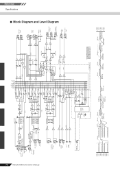
... RETURN LO BA [-10dBu] [0dBu] RO DIGITAL EFFECT (DSP) BA AUX [-14dBu] PFL +15V IN only MG124CX +30dBu +20dBu +10dBu 0dBu -10dBu -20dBu -30dBu -40dBu -50dBu -60dBu CH IN LINE Gain:Min [+10dBu...L MONITOR OUT [+4dBu] R PHONES [3mW @ 40ohms] AUX SEND *1 [+4dBu] EFFECT SEND *1 [+4dBu] MONITOR MIX *1 MODEL FUNCTION NAME MG124CX AUX EFFECT MG124C AUX1 AUX2 Clip Level Clip Level Clip Level Clip Level AUX SEND *1 [+4dBu] GROUP OUT [+4dBu] AUX SEND *1 [Nominal:-... [Nominal:-16dB] +30dBu +20dBu +10dBu 0dBu -10dBu -20dBu -30dBu Reference Specifications ■ Block Diagram and Level Diagram
... RETURN LO BA [-10dBu] [0dBu] RO DIGITAL EFFECT (DSP) BA AUX [-14dBu] PFL +15V IN only MG124CX +30dBu +20dBu +10dBu 0dBu -10dBu -20dBu -30dBu -40dBu -50dBu -60dBu CH IN LINE Gain:Min [+10dBu...L MONITOR OUT [+4dBu] R PHONES [3mW @ 40ohms] AUX SEND *1 [+4dBu] EFFECT SEND *1 [+4dBu] MONITOR MIX *1 MODEL FUNCTION NAME MG124CX AUX EFFECT MG124C AUX1 AUX2 Clip Level Clip Level Clip Level Clip Level AUX SEND *1 [+4dBu] GROUP OUT [+4dBu] AUX SEND *1 [Nominal:-... [Nominal:-16dB] +30dBu +20dBu +10dBu 0dBu -10dBu -20dBu -30dBu Reference Specifications ■ Block Diagram and Level Diagram