
User Manual
Page 11
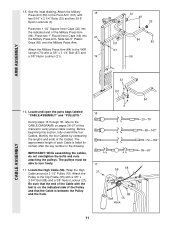
.... 17 17. Slide two 5" Plastic Grips (83) onto the Military Press Arm. Locate and open the parts bags labeled "CABLE ASSEMBLY" and "PULLEYS." 16 During steps 16 through 36, refer to verify proper cable routing. Attach the Pulley to the Pivot Arm (101) with a 3/8" x 3 3/4" Bolt (88) and a 3/8" Nylon Locknut (21). Before beginning this...
.... 17 17. Slide two 5" Plastic Grips (83) onto the Military Press Arm. Locate and open the parts bags labeled "CABLE ASSEMBLY" and "PULLEYS." 16 During steps 16 through 36, refer to verify proper cable routing. Attach the Pulley to the Pivot Arm (101) with a 3/8" x 3 3/4" Bolt (88) and a 3/8" Nylon Locknut (21). Before beginning this...
User Manual
Page 12
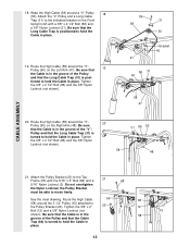
... 3/8" x 2 1/2" Bolt (86) and a 3/8" Nylon Locknut (21). Wrap the High Cable (58) around the "V"- 20 Pulley (50) on the Right Arm (48). Route the High Cable (58) around a "V"-Pulley 18 (50). Route the High Cable 55 66 (58) around the "V"Pulley (50) on the Front Upright (42) with the... Bolt (86) and the 3/8" Nylon Locknut (not shown). 58 31 86 50 48 CABLE ASSEMBLY 21. 18. Route the High Cable (58) around the 3 1/2" Pulley (15) attached to move freely. Be sure that the Cable 3 15 58 Trap (66) is in place. 19. the Pulley Bracket must be able...
... 3/8" x 2 1/2" Bolt (86) and a 3/8" Nylon Locknut (21). Wrap the High Cable (58) around the "V"- 20 Pulley (50) on the Right Arm (48). Route the High Cable (58) around a "V"-Pulley 18 (50). Route the High Cable 55 66 (58) around the "V"Pulley (50) on the Front Upright (42) with the... Bolt (86) and the 3/8" Nylon Locknut (not shown). 58 31 86 50 48 CABLE ASSEMBLY 21. 18. Route the High Cable (58) around the 3 1/2" Pulley (15) attached to move freely. Be sure that the Cable 3 15 58 Trap (66) is in place. 19. the Pulley Bracket must be able...
User Manual
Page 13
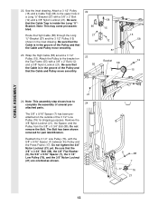
...Bolt (12) and a 3/8" Nylon Locknut (21). The Bolt has been shown removed for shipping purposes. Wrap the High Cable (58) around a 3 1/2" Pulley (15). Do not tighten the 3/8" Nylon Locknut (21) yet. Route the High Cable (58) through the Long "U"-Bracket (57) and the 3 1/2" Pulley (15) shown in the groove of the ...Pulley and that the Cable and Pulley move smoothly. 22 66 21 57 23 55 58 15 12 57 ...
...Bolt (12) and a 3/8" Nylon Locknut (21). The Bolt has been shown removed for shipping purposes. Wrap the High Cable (58) around a 3 1/2" Pulley (15). Do not tighten the 3/8" Nylon Locknut (21) yet. Route the High Cable (58) through the Long "U"-Bracket (57) and the 3 1/2" Pulley (15) shown in the groove of the ...Pulley and that the Cable and Pulley move smoothly. 22 66 21 57 23 55 58 15 12 57 ...
User Manual
Page 14
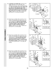
... shows view from other side 14 Locate the Low Cable (23). Route the Low 25 Cable under the 3 1/2" Low Pulley (76) attached to the upper hole in the 27 Press Frame (17). Route the Low Cable (23) around the Pulley as shown. Route the Low Cable (23) around the 3 1/2" Pulley (15) ...attached to the upper hole in the 28 Front Upright (42). CABLE ASSEMBLY 25. Be sure that the Cable is routed around the 3 1/2" Pulley (15) ...
... shows view from other side 14 Locate the Low Cable (23). Route the Low 25 Cable under the 3 1/2" Low Pulley (76) attached to the upper hole in the 27 Press Frame (17). Route the Low Cable (23) around the Pulley as shown. Route the Low Cable (23) around the 3 1/2" Pulley (15) ...attached to the upper hole in the 28 Front Upright (42). CABLE ASSEMBLY 25. Be sure that the Cable is routed around the 3 1/2" Pulley (15) ...
User Manual
Page 17
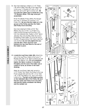
...Tighten a 5/16" Nylon Jam Nut (93) onto the Bolt. Slide the end of the Military Press Cable (72) onto the end of the Leg Press Cable to the Long "U"- assembled.) Route the Military Press Cable (72) through the Pivot Arm (101) from the indicated side. Do not fully tighten the second Jam... Nut. Attach a 3 1/2" Pulley 34 (15) and a Cable Trap (66) to the upper hole in the groove of the Cable to the ...
...Tighten a 5/16" Nylon Jam Nut (93) onto the Bolt. Slide the end of the Military Press Cable (72) onto the end of the Leg Press Cable to the Long "U"- assembled.) Route the Military Press Cable (72) through the Pivot Arm (101) from the indicated side. Do not fully tighten the second Jam... Nut. Attach a 3 1/2" Pulley 34 (15) and a Cable Trap (66) to the upper hole in the groove of the Cable to the ...
User Manual
Page 21
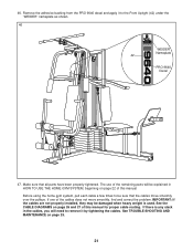
...cable routing. If there is used. The use of the cables does not move smoothly over the pulleys. Remove the adhesive backing from the PRO 9640 decal and apply it to remove it by tightening the cables. If one of the remaining parts will need to the Front Upright (42) under the "WEIDER" nameplate as shown. 46 WEIDER... Nameplate 42 PRO 9640 Decal 47. See TROUBLE-SHOOTING AND...
...cable routing. If there is used. The use of the cables does not move smoothly over the pulleys. Remove the adhesive backing from the PRO 9640 decal and apply it to remove it by tightening the cables. If one of the remaining parts will need to the Front Upright (42) under the "WEIDER" nameplate as shown. 46 WEIDER... Nameplate 42 PRO 9640 Decal 47. See TROUBLE-SHOOTING AND...
User Manual
Page 26
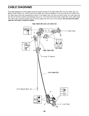
... positioning of the High Cable (58), the Low Cable (23), the Military Press Cable (72), and the Leg Press Cable (99). The insets show the proper routing of the cable traps. The cable traps should be sure that the cable traps do not touch or bind the cables. Use the diagrams to...damage may occur. Be sure that the four cables and the cable traps have not been correctly routed, the home gym system will not come off the pulleys. High Cable (58) and Low Cable (23) 7 5 23 4 1-High Pulley TOP VIEW 6 High Cable (58) 5-Long "U"-Bracket Low Cable (23) Front Weight Stack-8 4 3 ...
... positioning of the High Cable (58), the Low Cable (23), the Military Press Cable (72), and the Leg Press Cable (99). The insets show the proper routing of the cable traps. The cable traps should be sure that the cable traps do not touch or bind the cables. Use the diagrams to...damage may occur. Be sure that the four cables and the cable traps have not been correctly routed, the home gym system will not come off the pulleys. High Cable (58) and Low Cable (23) 7 5 23 4 1-High Pulley TOP VIEW 6 High Cable (58) 5-Long "U"-Bracket Low Cable (23) Front Weight Stack-8 4 3 ...

