

English Manual
Page 1
Serial Number Decal (under seat) • Assembly • Adjustments • Part List and Drawing WEIGHT SYSTEM EXERCISER User's Manual CAUTION Read all precautions and instructions in the space above for future reference. Write the serial number in this manual before using this manual for future reference. Model No. 831.15392.3 Serial No. Sears, Roebuck and Co., Hoffman Estates, IL 60179 Save this equipment.
Serial Number Decal (under seat) • Assembly • Adjustments • Part List and Drawing WEIGHT SYSTEM EXERCISER User's Manual CAUTION Read all precautions and instructions in the space above for future reference. Write the serial number in this manual before using this manual for future reference. Model No. 831.15392.3 Serial No. Sears, Roebuck and Co., Hoffman Estates, IL 60179 Save this equipment.

English Manual
Page 2
Remove the PART IDENTIFICATION CHART and PART LIST/EXPLODED DRAWING before beginning assembly. Mountain Time, to order a free replacement decal. Keep hands and fingers clear of this area. 2 until 6 p.m. WARNING DECAL PLACEMENT The decals shown here have been placed on the resistance system. If a decal is missing or illegible, please call toll-free 1-877-992-5999, Monday through Friday, 6 a.m. Apply the decal in the center of this manual. TABLE OF CONTENTS WARNING DECAL PLACEMENT 2 IMPORTANT PRECAUTIONS 3 BEFORE YOU BEGIN 4 ASSEMBLY 5 ADJUSTMENTS 13 CABLE DIAGRAM 17 ...
Remove the PART IDENTIFICATION CHART and PART LIST/EXPLODED DRAWING before beginning assembly. Mountain Time, to order a free replacement decal. Keep hands and fingers clear of this area. 2 until 6 p.m. WARNING DECAL PLACEMENT The decals shown here have been placed on the resistance system. If a decal is missing or illegible, please call toll-free 1-877-992-5999, Monday through Friday, 6 a.m. Apply the decal in the center of this manual. TABLE OF CONTENTS WARNING DECAL PLACEMENT 2 IMPORTANT PRECAUTIONS 3 BEFORE YOU BEGIN 4 ASSEMBLY 5 ADJUSTMENTS 13 CABLE DIAGRAM 17 ...

English Manual
Page 3
... Make sure the rings on the pulleys at least every two years. 21. Sears assumes no responsibility for personal injury or property damage sustained by WEIDER MAX PACK. Keep clear of 300 pounds. 12. Do not hang on a level surface. Do not use the resistance system in this manual before ... exercising. 10. This is not designed to the horizontal position and make sure that the cables are adequately informed of 35 or persons with a MAX by or through the use only. Make sure the storage knob is in a garage or covered patio, or near water. 5. The resistance system...
... Make sure the rings on the pulleys at least every two years. 21. Sears assumes no responsibility for personal injury or property damage sustained by WEIDER MAX PACK. Keep clear of 300 pounds. 12. Do not hang on a level surface. Do not use the resistance system in this manual before ... exercising. 10. This is not designed to the horizontal position and make sure that the cables are adequately informed of 35 or persons with a MAX by or through the use only. Make sure the storage knob is in a garage or covered patio, or near water. 5. The resistance system...

English Manual
Page 4
... offers a selection of stations designed to achieve the specific results you want. To help you have questions after reading this manual for selecting the innovative MAX by WEIDER™ ADVANTAGE resistance system. The serial number can be found on a decal attached to tone your body, build dramatic muscle size and strength, or...
... offers a selection of stations designed to achieve the specific results you want. To help you have questions after reading this manual for selecting the innovative MAX by WEIDER™ ADVANTAGE resistance system. The serial number can be found on a decal attached to tone your body, build dramatic muscle size and strength, or...
English Manual
Page 5
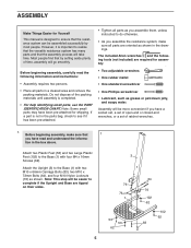
The included Allen wrenches and the following information and instructions: • Assembly requires two persons. • Place all parts in the box above. Attach the Upright (3) to the Base (1) with four M4 x 16mm Screws (62). Note: This step will be easier to the Base (1) with two M10 x 66mm Carriage Bolts (83), two M10 x 72mm Bolts (64), and four M10 Nylon Locknuts (76) as shown. ASSEMBLY Make Things Easier for Yourself This manual is designed to ensure that the resistance system can be assembled successfully by setting aside plenty of time, assembly will go smoothly....
The included Allen wrenches and the following information and instructions: • Assembly requires two persons. • Place all parts in the box above. Attach the Upright (3) to the Base (1) with four M4 x 16mm Screws (62). Note: This step will be easier to the Base (1) with two M10 x 66mm Carriage Bolts (83), two M10 x 72mm Bolts (64), and four M10 Nylon Locknuts (76) as shown. ASSEMBLY Make Things Easier for Yourself This manual is designed to ensure that the resistance system can be assembled successfully by setting aside plenty of time, assembly will go smoothly....
English Manual
Page 6
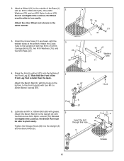
Lubricate an M10 x 103mm Bolt (66) with grease. 5 Attach the Bench Rail (5) to the outside of the Base (1) with an M10 x 78mm Bolt (81), three M10 2 Washers (75), and an M10 Nylon Locknut (76). Attach the other Wheel (not shown) in the same manner. 3. Orient the Cross Tube (11) as shown, with four M10 x 25mm Button Screws (87). 87 87 5 Hook 6 Front 27 5. Press the Front Leg Foot (27) onto the bottom of the Front Leg Foot is taller than the back. Note that the front of 4 the Front Leg (6). Do not overtighten the Locknut; Attach a Wheel (31) to the Upright (3) with two...
Lubricate an M10 x 103mm Bolt (66) with grease. 5 Attach the Bench Rail (5) to the outside of the Base (1) with an M10 x 78mm Bolt (81), three M10 2 Washers (75), and an M10 Nylon Locknut (76). Attach the other Wheel (not shown) in the same manner. 3. Orient the Cross Tube (11) as shown, with four M10 x 25mm Button Screws (87). 87 87 5 Hook 6 Front 27 5. Press the Front Leg Foot (27) onto the bottom of the Front Leg Foot is taller than the back. Note that the front of 4 the Front Leg (6). Do not overtighten the Locknut; Attach a Wheel (31) to the Upright (3) with two...
English Manual
Page 7
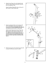
Attach two Eyebolts (34) to the Front Leg (6) with two M8 Washers (59) and two M8 Nylon Locknuts (65). Do not overtighten the Locknuts; Make sure that the Eyebolts (34) are not, turn the Top Frame around and reattach it. 7 65 59 70 75 93 10 34 65 59 Side View 10 4 34 4 8. Attach the Leg Lever (7) to the Top Frame (10) with a Long Pin (107) and a Cotter Pin (108). 34 8 107 6 7 108 7 Attach the Name Plate (89) to the Upright (3) with two M4 x 16mm Screws (62). 62 89 62 103 87 87 103 3 7. the Eyebolts must be able to the Lat Tower (4) with two M10 x 65mm Button Screws ...
Attach two Eyebolts (34) to the Front Leg (6) with two M8 Washers (59) and two M8 Nylon Locknuts (65). Do not overtighten the Locknuts; Make sure that the Eyebolts (34) are not, turn the Top Frame around and reattach it. 7 65 59 70 75 93 10 34 65 59 Side View 10 4 34 4 8. Attach the Leg Lever (7) to the Top Frame (10) with a Long Pin (107) and a Cotter Pin (108). 34 8 107 6 7 108 7 Attach the Name Plate (89) to the Upright (3) with two M4 x 16mm Screws (62). 62 89 62 103 87 87 103 3 7. the Eyebolts must be able to the Lat Tower (4) with two M10 x 65mm Button Screws ...

English Manual
Page 8
Attach the Seat Knob (45) to one end of the Flange Nuts are against the Bench Rail. Make sure that three threads are oriented as shown in the Bench Rail (5). 11 19 57 12 45 13 5 19 97 46 39 Adjustment Hole 97 46 39 97 Wide Side 46 97 8 Attach two 8mm Metal Spacers (97), a 61mm Metal Spacer (39), and two Bearing Wheels (46) to the Seat Carriage (12) with an M8 x 104mm Bolt (60) and an M8 Nylon Locknut (65) as shown. the Seat Knob (not shown) will go, and set of the Bench Rail (5) and properly tighten the M8 Flange Nuts (19). Attach the Seat to the other end of all ...
Attach the Seat Knob (45) to one end of the Flange Nuts are against the Bench Rail. Make sure that three threads are oriented as shown in the Bench Rail (5). 11 19 57 12 45 13 5 19 97 46 39 Adjustment Hole 97 46 39 97 Wide Side 46 97 8 Attach two 8mm Metal Spacers (97), a 61mm Metal Spacer (39), and two Bearing Wheels (46) to the Seat Carriage (12) with an M8 x 104mm Bolt (60) and an M8 Nylon Locknut (65) as shown. the Seat Knob (not shown) will go, and set of the Bench Rail (5) and properly tighten the M8 Flange Nuts (19). Attach the Seat to the other end of all ...
English Manual
Page 9
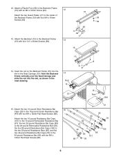
12. Insert the rod on the Backrest Frame (15) into the slot, as shown in the Seat Carriage (12). Attach a Plastic Foot (53) to the Backrest Frame (15) with an M4 x 16mm Screw (62). 12 Attach the two Guard Plates (17) to the 10-pound Center Resistance Bar (44) with four M4 x 16mm Screws (62). 15 53 62 13. Attach the two 10-pound Short Resistance Bar 15 Caps (20) to the inside of the Backrest Frame (15) with two M4 x 12mm Flat Head Screws (85). Attach the Backrest (14) to the 40-pound Resistance Bar (96) with four 1/4" x 45mm Screws (58). 62 17 62 17 13 14 15 14....
12. Insert the rod on the Backrest Frame (15) into the slot, as shown in the Seat Carriage (12). Attach a Plastic Foot (53) to the Backrest Frame (15) with an M4 x 16mm Screw (62). 12 Attach the two Guard Plates (17) to the 10-pound Center Resistance Bar (44) with four M4 x 16mm Screws (62). 15 53 62 13. Attach the two 10-pound Short Resistance Bar 15 Caps (20) to the inside of the Backrest Frame (15) with two M4 x 12mm Flat Head Screws (85). Attach the Backrest (14) to the 40-pound Resistance Bar (96) with four 1/4" x 45mm Screws (58). 62 17 62 17 13 14 15 14....
English Manual
Page 10
Make sure the Tray is on this side 4 35 18 18 17 96 44 95 95 36 Rods 67 80 71 11 104 28 22 Rod 76 18 75 76 29 110 73 28 110 80 19 44 76 74 71 28 74 80 "U"-Channel 76 94 24 10 Attach the Cover Plate (72), with an M10 x 42mm Button Bolt (71) and an M10 Nylon Locknut (76). 18. Be sure the Cable is oriented as shown. 19. Secure the Swivel Arm with two M8 x 19mm Button Screws (86). 17. Wrap the Long Cable (80) around a 90mm Pulley (28). Attach the Pulley inside of the Swivel Arm (22) with the edges up Rings on the indicated side of the Swivel Arm. Locate...
Make sure the Tray is on this side 4 35 18 18 17 96 44 95 95 36 Rods 67 80 71 11 104 28 22 Rod 76 18 75 76 29 110 73 28 110 80 19 44 76 74 71 28 74 80 "U"-Channel 76 94 24 10 Attach the Cover Plate (72), with an M10 x 42mm Button Bolt (71) and an M10 Nylon Locknut (76). 18. Be sure the Cable is oriented as shown. 19. Secure the Swivel Arm with two M8 x 19mm Button Screws (86). 17. Wrap the Long Cable (80) around a 90mm Pulley (28). Attach the Pulley inside of the Swivel Arm (22) with the edges up Rings on the indicated side of the Swivel Arm. Locate...

English Manual
Page 11
Wrap the Long Cable (80) around a 90mm Pulley (28). Have a second person pull on the Long Cable (80) to the indicated M10 x 147mm Carriage Bolt (73) with an M10 x 127mm Button Bolt (56) and an M10 Nylon Locknut (76). Note: The Bolt will be packaged separately for identification. Wrap the Long Cable (80) over a 90mm Pulley (28). Attach the Pulley, a Cable Trap (29), an M10 Washer (75), and two Finger Guards (110) to create slack in the Swivel Arm. 71 104 Rod 80 Insert the Swivel Arm (22) into the welded tube on the 10-pound Center Resistance Bar (not shown). Attach a Pulley ...
Wrap the Long Cable (80) around a 90mm Pulley (28). Have a second person pull on the Long Cable (80) to the indicated M10 x 147mm Carriage Bolt (73) with an M10 x 127mm Button Bolt (56) and an M10 Nylon Locknut (76). Note: The Bolt will be packaged separately for identification. Wrap the Long Cable (80) over a 90mm Pulley (28). Attach the Pulley, a Cable Trap (29), an M10 Washer (75), and two Finger Guards (110) to create slack in the Swivel Arm. 71 104 Rod 80 Insert the Swivel Arm (22) into the welded tube on the 10-pound Center Resistance Bar (not shown). Attach a Pulley ...
English Manual
Page 12
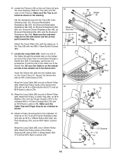
Route the longest end of the Leg Lever Cable (32) through the Front 27 Leg (6). Slide two Foam Pads (26) onto the tube. Attach the Curl Pad (77) to a High Pulley Housing (21) with an M10 x 42mm Button Bolt (71) and an M10 Nylon Locknut (76). IMPORTANT: If the cables are the same length and a third end that is longer. Attach the Pulley to the Curl Post (40) with an M10 x 91mm Bolt (90), two 26mm Spacers (52), two M10 Washers (75), and an M10 Nylon Locknut (76). The use of the hole in ADJUSTMENTS, beginning on page 17 for proper cable routing. 12 40 82 Make sure ...
Route the longest end of the Leg Lever Cable (32) through the Front 27 Leg (6). Slide two Foam Pads (26) onto the tube. Attach the Curl Pad (77) to a High Pulley Housing (21) with an M10 x 42mm Button Bolt (71) and an M10 Nylon Locknut (76). IMPORTANT: If the cables are the same length and a third end that is longer. Attach the Pulley to the Curl Post (40) with an M10 x 91mm Bolt (90), two 26mm Spacers (52), two M10 Washers (75), and an M10 Nylon Locknut (76). The use of the hole in ADJUSTMENTS, beginning on page 17 for proper cable routing. 12 40 82 Make sure ...

English Manual
Page 13
Replace worn parts immediately. Attach the two ends of the Leg Lever Cable to get the most benefit from your exercise program. Then, pull the Seat Knob (45) out as far as it will go , and slide the Seat to the Leg Lever with a Cable Clip (51). See the EXERCISE GUIDELINES on page 17 for each time you use . To use the Leg Lever (7), it will go , and turn the Knob so that the pin rests at an automotive or department store. Store the ends of the Leg Lever Cable on the hook under the Bench Rail (not shown). 34 21 Ball 33 80 51 32 7 32 109 108 51 ADJUSTING THE SEAT The ...
Replace worn parts immediately. Attach the two ends of the Leg Lever Cable to get the most benefit from your exercise program. Then, pull the Seat Knob (45) out as far as it will go , and slide the Seat to the Leg Lever with a Cable Clip (51). See the EXERCISE GUIDELINES on page 17 for each time you use . To use the Leg Lever (7), it will go , and turn the Knob so that the pin rests at an automotive or department store. Store the ends of the Leg Lever Cable on the hook under the Bench Rail (not shown). 34 21 Ball 33 80 51 32 7 32 109 108 51 ADJUSTING THE SEAT The ...

English Manual
Page 14
... page 13), attach a Short Handle (49) to the resistance system by calling toll-free 1-877-992-5999 and asking for model number WEMC0642 (100-pound MAX PACK) or WEMC0942 (200-pound MAX PACK). 33 51 49 80 "U"-Channel 67 Resistance Bars 35 36 44 "U"-Channel 80 14
... page 13), attach a Short Handle (49) to the resistance system by calling toll-free 1-877-992-5999 and asking for model number WEMC0642 (100-pound MAX PACK) or WEMC0942 (200-pound MAX PACK). 33 51 49 80 "U"-Channel 67 Resistance Bars 35 36 44 "U"-Channel 80 14
English Manual
Page 15
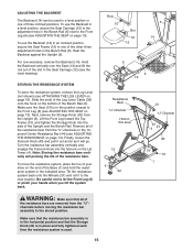
STORING THE RESISTANCE SYSTEM To store the resistance system, remove the Leg Lever (not shown) (see ATTACHING THE LEG LEVER on the Lat Tower (4). Next, remove the Storage Knob (30) from the "U"-channels on the 10pound Center Resistance Bar (44) (see ADJUSTING THE SEAT on the end of your hands when you tilt the system back. Remove all of the resistance bars are removed from the "U"channels before moving the resistance bar assembly to let the Front Leg (6) or pinch your shoe on page 13). Be careful not to the stored position. ADJUSTING THE BACKREST The Backrest (14) can be used . ...
STORING THE RESISTANCE SYSTEM To store the resistance system, remove the Leg Lever (not shown) (see ATTACHING THE LEG LEVER on the Lat Tower (4). Next, remove the Storage Knob (30) from the "U"-channels on the 10pound Center Resistance Bar (44) (see ADJUSTING THE SEAT on the end of your hands when you tilt the system back. Remove all of the resistance bars are removed from the "U"channels before moving the resistance bar assembly to let the Front Leg (6) or pinch your shoe on page 13). Be careful not to the stored position. ADJUSTING THE BACKREST The Backrest (14) can be used . ...

English Manual
Page 16
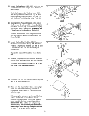
USING THE REMOVABLE RESISTANCE BARS The Removable Resistance Bars (36, 67) can be used to exercise apart from the Front Leg (6) by removing the Long and Short Pins (107, 109). Attach the Leg Lever Cable (32) to the Leg Lever with the Long Pin (107) and a Cotter Pin (108). Remove the Leg Lever from the resistance system, as shown in the video or on the rings point toward the Tray. ATTACHING THE CURL PAD to the Front Leg (6) with the Short Pin (109) and a Cotter Pin. Remove the Curl Post (40) from the side shown, so that does not require it with the Knob (55). To remove a ...
USING THE REMOVABLE RESISTANCE BARS The Removable Resistance Bars (36, 67) can be used to exercise apart from the Front Leg (6) by removing the Long and Short Pins (107, 109). Attach the Leg Lever Cable (32) to the Leg Lever with the Long Pin (107) and a Cotter Pin (108). Remove the Leg Lever from the resistance system, as shown in the video or on the rings point toward the Tray. ATTACHING THE CURL PAD to the Front Leg (6) with the Short Pin (109) and a Cotter Pin. Remove the Curl Post (40) from the side shown, so that does not require it with the Knob (55). To remove a ...
English Manual
Page 17
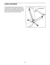
The 5 numbers show the correct route for the cable. CABLE DIAGRAM The cable diagram shows the proper routing of the Long Cable (80). Use the diagram to make sure that the cable has been assembled correctly. Long Cable (80) 7 6 4 3 2 1 17 If the cable has not been correctly routed, the resistance system will not function properly and damage may occur.
The 5 numbers show the correct route for the cable. CABLE DIAGRAM The cable diagram shows the proper routing of the Long Cable (80). Use the diagram to make sure that the cable has been assembled correctly. Long Cable (80) 7 6 4 3 2 1 17 If the cable has not been correctly routed, the resistance system will not function properly and damage may occur.

English Manual
Page 18
A "set . When you can tone your body time to regenerate. Determining the exact length of time for each exercise depends upon the individual user. Find out what is an individual matter. Warming up prepares your body for 1 minute after each set . To give your muscles by increasing circulation, raising your body temperature and delivering more sets rather than by changing the number of each repetition should include 6 to get a complete and well-balanced fitness program. Once you perform. The repetitions in each week to warm up . Proper breathing is an essential ...
A "set . When you can tone your body time to regenerate. Determining the exact length of time for each exercise depends upon the individual user. Find out what is an individual matter. Warming up prepares your body for 1 minute after each set . To give your muscles by increasing circulation, raising your body temperature and delivering more sets rather than by changing the number of each repetition should include 6 to get a complete and well-balanced fitness program. Once you perform. The repetitions in each week to warm up . Proper breathing is an essential ...

English Manual
Page 19
Include stretches for each exercise. Anterior Deltoid (shoulder) M. Rhomboideus (upper back) Q. Latissimus Dorsi (mid back) T. Gluteus Maximus (buttocks) W. Plan to spend the first couple of weeks familiarizing yourself with 5 to 10 minutes of stretching. Move slowly as you stretch and do not bounce. STAYING MOTIVATED For motivation, keep a record of time after each workout is to increase flexibility. Sartorius (front of arm) D. Record your arms and legs. A B C D E F G H I . Biceps (front of thigh) J. Hip Flexors (upper thigh) G. Spinae ...
Include stretches for each exercise. Anterior Deltoid (shoulder) M. Rhomboideus (upper back) Q. Latissimus Dorsi (mid back) T. Gluteus Maximus (buttocks) W. Plan to spend the first couple of weeks familiarizing yourself with 5 to 10 minutes of stretching. Move slowly as you stretch and do not bounce. STAYING MOTIVATED For motivation, keep a record of time after each workout is to increase flexibility. Sartorius (front of arm) D. Record your arms and legs. A B C D E F G H I . Biceps (front of thigh) J. Hip Flexors (upper thigh) G. Spinae ...
English Manual
Page 20
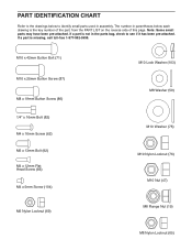
If a part is not in the parts bag, check to identify small parts used in parentheses below to see if it has been pre-attached. PART IDENTIFICATION CHART Refer to the drawings below each drawing is the key number of the part, from the PART LIST on the reverse side of this page. Note: Some small parts may have been pre-attached. M10 x 42mm Button Bolt (71) M10 x 25mm Button Screw (87) M8 x 19mm Button Screw (86) 1/4" x 16mm Bolt (82) M4 x 16mm Screw (62) M6 x 13mm Bolt (92) M4 x 12mm Flat Head Screw (85) M4 x 5mm Screw (104) M10 Lock Washer (103) M8 Washer (59) M10 Washer (75) M10 ...
If a part is not in the parts bag, check to identify small parts used in parentheses below to see if it has been pre-attached. PART IDENTIFICATION CHART Refer to the drawings below each drawing is the key number of the part, from the PART LIST on the reverse side of this page. Note: Some small parts may have been pre-attached. M10 x 42mm Button Bolt (71) M10 x 25mm Button Screw (87) M8 x 19mm Button Screw (86) 1/4" x 16mm Bolt (82) M4 x 16mm Screw (62) M6 x 13mm Bolt (92) M4 x 12mm Flat Head Screw (85) M4 x 5mm Screw (104) M10 Lock Washer (103) M8 Washer (59) M10 Washer (75) M10 ...