
English Manual
Page 1
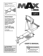
... all precautions and instructions in the space above for future reference. Save this equipment. USER'S MANUAL Visit our website at www.weiderfitness.com new products, prizes, fitness tips, and much more! If you have questions, or if a part is damaged or missing, PLEASE CONTACT OUR CUSTOMER SERVICE DEPARTMENT DIRECTLY. Write the serial number in this manual before using this manual for future reference...
... all precautions and instructions in the space above for future reference. Save this equipment. USER'S MANUAL Visit our website at www.weiderfitness.com new products, prizes, fitness tips, and much more! If you have questions, or if a part is damaged or missing, PLEASE CONTACT OUR CUSTOMER SERVICE DEPARTMENT DIRECTLY. Write the serial number in this manual before using this manual for future reference...
English Manual
Page 2
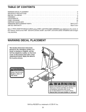
... fingers clear of ICON IP, Inc. 2 Apply the decal in the center of this area. TABLE OF CONTENTS WARNING DECAL PLACEMENT 2 IMPORTANT PRECAUTIONS 3 BEFORE YOU BEGIN 4 ASSEMBLY 5 ADJUSTMENTS 13 CABLE DIAGRAM 16 EXERCISE GUIDELINES 17 ORDERING REPLACEMENT PARTS Back Cover LIMITED WARRANTY Back Cover Note: A PART IDENTIFICATION CHART and a PART LIST/EXPLODED DRAWING are attached in the location shown. If a decal is a trademark of this manual and order a free replacement decal.
... fingers clear of ICON IP, Inc. 2 Apply the decal in the center of this area. TABLE OF CONTENTS WARNING DECAL PLACEMENT 2 IMPORTANT PRECAUTIONS 3 BEFORE YOU BEGIN 4 ASSEMBLY 5 ADJUSTMENTS 13 CABLE DIAGRAM 16 EXERCISE GUIDELINES 17 ORDERING REPLACEMENT PARTS Back Cover LIMITED WARRANTY Back Cover Note: A PART IDENTIFICATION CHART and a PART LIST/EXPLODED DRAWING are attached in the location shown. If a decal is a trademark of this manual and order a free replacement decal.
English Manual
Page 3
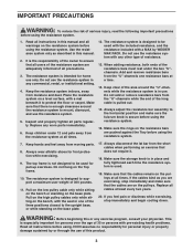
...-up exercises. Always adjust the resistance bar assembly to support a maximum user weight of this manual and all times. The resistance system is designed to the horizontal position and make sure that does not require it to be used with the included resistance, and the resistance included with pre-existing health problems. Read all cables at all parts regularly. Make sure the storage knob is secure before using the resistance system...
...-up exercises. Always adjust the resistance bar assembly to support a maximum user weight of this manual and all times. The resistance system is designed to the horizontal position and make sure that does not require it to be used with the included resistance, and the resistance included with pre-existing health problems. Read all cables at all parts regularly. Make sure the storage knob is secure before using the resistance system...
English Manual
Page 4
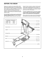
... the specific results you want. For your benefit, read this manual). ASSEMBLED DIMENSIONS: Height: 82 in. / 208 cm Width: 64 in. / 163 cm Depth: 80 in. / 203 cm Fulcrum Knob Upright Storage Knob Backrest Seat Leg Lever Top Frame Lat Tower High Pulley Resistance Bars "U"-Channel Foot Plate Low Pulley Base Plate Seat Knob Lat Bar 4 To help you to develop every major muscle group of this manual. The serial number can...
... the specific results you want. For your benefit, read this manual). ASSEMBLED DIMENSIONS: Height: 82 in. / 208 cm Width: 64 in. / 163 cm Depth: 80 in. / 203 cm Fulcrum Knob Upright Storage Knob Backrest Seat Leg Lever Top Frame Lat Tower High Pulley Resistance Bars "U"-Channel Foot Plate Low Pulley Base Plate Seat Knob Lat Bar 4 To help you to develop every major muscle group of this manual. The serial number can...
English Manual
Page 5
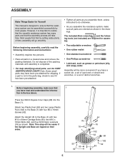
...- Attach the Upright (3) to the Base (1) with two M10 x 66mm Carriage Bolts (83), two M10 x 72mm Bolts (64), and four M10 Nylon Locknuts (76) as shown in the box above. The included Allen wrenches and the following information and instructions: • Assembly requires two persons. • Place all parts in a cleared area and remove the packing materials. Note: This step...
...- Attach the Upright (3) to the Base (1) with two M10 x 66mm Carriage Bolts (83), two M10 x 72mm Bolts (64), and four M10 Nylon Locknuts (76) as shown in the box above. The included Allen wrenches and the following information and instructions: • Assembly requires two persons. • Place all parts in a cleared area and remove the packing materials. Note: This step...

English Manual
Page 6
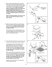
... hole 66 5 Lubricate 6 Lubricate an M10 x 103mm Bolt (66) with the welded tubes at the bottom. Tighten the Storage Knob (30) into the top of the Base (1) 2 with two M10 x 53mm Carriage Bolts (61) and two M10 Nylon Locknuts (76). 5. Attach the Foot Plate (23) and the Cross Tube to pivot easily. Attach a Wheel (31) to the Front Leg (6) with an...
... hole 66 5 Lubricate 6 Lubricate an M10 x 103mm Bolt (66) with the welded tubes at the bottom. Tighten the Storage Knob (30) into the top of the Base (1) 2 with two M10 x 53mm Carriage Bolts (61) and two M10 Nylon Locknuts (76). 5. Attach the Foot Plate (23) and the Cross Tube to pivot easily. Attach a Wheel (31) to the Front Leg (6) with an...

English Manual
Page 7
...able to the Upright (3) with the slot on the side shown. Attach the Leg Lever Bumper (55) to pivot easily. 34 8 Lubricate 56 42 6 7 Slot 55 76 42 77 7 Attach the Leg Lever to the Top Frame (10) with grease. Lubricate an M10 x 68mm Bolt (56) with...Leg (6) with the Bolt and an M10 Nylon Locknut (76). If they are oriented as shown in the inset drawing. Orient the Leg Lever (7) with 6 four M10 x 25mm Button Head Screws (87), and four M10 Lock Washers (103). 6. Attach the Lat Tower (4) to rotate freely. Press a 38mm Round Inner Cap (38) into the Leg Lever (7). Press...
...able to the Upright (3) with the slot on the side shown. Attach the Leg Lever Bumper (55) to pivot easily. 34 8 Lubricate 56 42 6 7 Slot 55 76 42 77 7 Attach the Leg Lever to the Top Frame (10) with grease. Lubricate an M10 x 68mm Bolt (56) with...Leg (6) with the Bolt and an M10 Nylon Locknut (76). If they are oriented as shown in the inset drawing. Orient the Leg Lever (7) with 6 four M10 x 25mm Button Head Screws (87), and four M10 Lock Washers (103). 6. Attach the Lat Tower (4) to rotate freely. Press a 38mm Round Inner Cap (38) into the Leg Lever (7). Press...
English Manual
Page 8
... Button Head Bolt (60) and an M8 Nylon Locknut (65) as shown in the inset drawing; Make sure that the serrated edge of the Seat Carriage (12) in the Bench Rail (5). 9 60 12 Attach second set the Seat Carriage (12) on the Seat (13), hold the wheel assembly firmly against the Seat Carriage. 9. Do not overtighten the Locknut; Attach the Seat Knob (45...
... Button Head Bolt (60) and an M8 Nylon Locknut (65) as shown in the inset drawing; Make sure that the serrated edge of the Seat Carriage (12) in the Bench Rail (5). 9 60 12 Attach second set the Seat Carriage (12) on the Seat (13), hold the wheel assembly firmly against the Seat Carriage. 9. Do not overtighten the Locknut; Attach the Seat Knob (45...

English Manual
Page 9
...Resistance Bar Cover Plate with four M4 x 16mm Screws (62). 13. Insert the rod on the Backrest Frame (15) into the slot, as shown. Orient the Backrest (14) and the Backrest Backing (8) as shown in the Seat Carriage (12). Using twelve M4 x 12mm Flat Head Screws (85), attach the two 10-pound Caps (101) to the 10pound Removable Resistance Bar...95 36 67 79 85 44 85 85 100 85 88 101 85 20 15. Press two 25mm Square Inner Caps (54) into the indicated end of the Cover Plate. 105 Edges up . 15 Attach the 80-pound Top Frame (105) to the back of the Backrest Frame (...
...Resistance Bar Cover Plate with four M4 x 16mm Screws (62). 13. Insert the rod on the Backrest Frame (15) into the slot, as shown. Orient the Backrest (14) and the Backrest Backing (8) as shown in the Seat Carriage (12). Using twelve M4 x 12mm Flat Head Screws (85), attach the two 10-pound Caps (101) to the 10pound Removable Resistance Bar...95 36 67 79 85 44 85 85 100 85 88 101 85 20 15. Press two 25mm Square Inner Caps (54) into the indicated end of the Cover Plate. 105 Edges up . 15 Attach the 80-pound Top Frame (105) to the back of the Backrest Frame (...
English Manual
Page 10
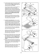
Set the Resistance Bars into the welded tube on the Lat Tower (4) (see the inset drawing). Orient the Cover Plate (72) as shown in the drawing. Locate the Long Cable (80). Insert one end of the Cable through a Swivel Arm (22). Attach the Pulley inside of a screwdriver to the indicated M10 x 140mm Carriage Bolt (73) with an M10 x 42mm Button Head Bolt (71) and an...
Set the Resistance Bars into the welded tube on the Lat Tower (4) (see the inset drawing). Orient the Cover Plate (72) as shown in the drawing. Locate the Long Cable (80). Insert one end of the Cable through a Swivel Arm (22). Attach the Pulley inside of a screwdriver to the indicated M10 x 140mm Carriage Bolt (73) with an M10 x 42mm Button Head Bolt (71) and an...

English Manual
Page 11
... Long Cable (80) around a 90mm Pulley (28). Attach the Pulley and a Pulley Guard (29) to create slack in the Swivel Arm. Have a sec- Be sure the Cable is on the Long Cable (80) to the Upright (3) with an M4 x 5mm Screw (104). Secure the Swivel Arm with an M10 x 113mm Button Head Bolt (40...Attach the Pulley inside of the Cross Tube (11) and then through the welded tube on the 10-pound Center Resistance Bar (44) with an M10 Nylon Locknut (76). Insert the Swivel Arm (22) into the welded tube on the 10-pound Center Resistance Bar (not shown). Attach the Pulley and a Pulley ...
... Long Cable (80) around a 90mm Pulley (28). Attach the Pulley and a Pulley Guard (29) to create slack in the Swivel Arm. Have a sec- Be sure the Cable is on the Long Cable (80) to the Upright (3) with an M4 x 5mm Screw (104). Secure the Swivel Arm with an M10 x 113mm Button Head Bolt (40...Attach the Pulley inside of the Cross Tube (11) and then through the welded tube on the 10-pound Center Resistance Bar (44) with an M10 Nylon Locknut (76). Insert the Swivel Arm (22) into the welded tube on the 10-pound Center Resistance Bar (not shown). Attach the Pulley and a Pulley ...
English Manual
Page 12
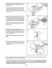
... Bolt (63) and an M10 Nylon Locknut (76). 25. Locate the two Short Cables (33). Route the longest end of the hole in ADJUSTMENTS, beginning on the following page. If the cable does not move smoothly, find and correct the problem. Attach a 90mm Pulley (28) inside of the remaining parts will be damaged when heavy resistance is above the Leg Lever Cable (32). The use...
... Bolt (63) and an M10 Nylon Locknut (76). 25. Locate the two Short Cables (33). Route the longest end of the hole in ADJUSTMENTS, beginning on the following page. If the cable does not move smoothly, find and correct the problem. Attach a 90mm Pulley (28) inside of the remaining parts will be damaged when heavy resistance is above the Leg Lever Cable (32). The use...
English Manual
Page 13
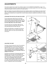
... to adjust the resistance system. To perform row exercises, the leg press strap must be attached to the long cable (see ADJUSTING THE BACKREST on the Bench Rail (5). First, remove the Backrest (14) from your exercise program. Remove the high pulleys, and detach the Leg Lever Cable (32), when not in order to the end of the Short Cable (33) without the ball to engage the Seat Knob. Replace worn parts immediately. ADJUSTMENTS...
... to adjust the resistance system. To perform row exercises, the leg press strap must be attached to the long cable (see ADJUSTING THE BACKREST on the Bench Rail (5). First, remove the Backrest (14) from your exercise program. Remove the high pulleys, and detach the Leg Lever Cable (32), when not in order to the end of the Short Cable (33) without the ball to engage the Seat Knob. Replace worn parts immediately. ADJUSTMENTS...
English Manual
Page 14
... the resistance bar. If more resistance is pulled out. Then, attach the Short Handle to the Short Cables (33), with a Cable Clip (51). Attach the Leg Press Strap (not shown) to both ends of this manual and ask for model number WEMC0943. The rings on the Removable Resistance Bars (36, 67) must be used, and finish with the heaviest resistance bar to -free telephone number on page 13). As the resistance bars bend...
... the resistance bar. If more resistance is pulled out. Then, attach the Short Handle to the Short Cables (33), with a Cable Clip (51). Attach the Leg Press Strap (not shown) to both ends of this manual and ask for model number WEMC0943. The rings on the Removable Resistance Bars (36, 67) must be used, and finish with the heaviest resistance bar to -free telephone number on page 13). As the resistance bars bend...

English Manual
Page 15
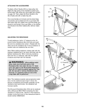
...). To use the Backrest in a level position, secure the Seat Carriage (12) to the adjustment hole in the Bench Rail (5) next to the Front Leg (6) (see ADJUSTING THE RESISTANCE on the Lat Tower (4). To move the resistance system, place the toe of your hands when you tilt the system back. Remove all of the resistance bars are removed from the "U"channels before moving the resistance bar assembly to...
...). To use the Backrest in a level position, secure the Seat Carriage (12) to the adjustment hole in the Bench Rail (5) next to the Front Leg (6) (see ADJUSTING THE RESISTANCE on the Lat Tower (4). To move the resistance system, place the toe of your hands when you tilt the system back. Remove all of the resistance bars are removed from the "U"channels before moving the resistance bar assembly to...

English Manual
Page 16
... Rings CABLE DIAGRAM The cable diagram shows the proper routing of the Tray (35). 67 36 To replace the Removable Resistance Bars (36, 67), slide them into the Tray (35) from the resistance system, as shown in the video or on the rings point toward the Tray. Use the diagram to exercise apart from the side shown, so that the Cable has been assembled correctly. To remove a Resistance Bar...
... Rings CABLE DIAGRAM The cable diagram shows the proper routing of the Tray (35). 67 36 To replace the Removable Resistance Bars (36, 67), slide them into the Tray (35) from the resistance system, as shown in the video or on the rings point toward the Tray. Use the diagram to exercise apart from the side shown, so that the Cable has been assembled correctly. To remove a Resistance Bar...
English Manual
Page 17
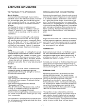
... muscles by changing the number of each workout, as well as running on a treadmill or riding on an elliptical or exercise bike, on Tuesday and Thursday. • Rest from session to their capacity. Schedule your workouts, vary the exercises from both strength training and aerobic exercise for more oxygen to 10 different exercises. EXERCISE FORM Maintaining proper form is an essential part of day when your exercise program. The...
... muscles by changing the number of each workout, as well as running on a treadmill or riding on an elliptical or exercise bike, on Tuesday and Thursday. • Rest from session to their capacity. Schedule your workouts, vary the exercises from both strength training and aerobic exercise for more oxygen to 10 different exercises. EXERCISE FORM Maintaining proper form is an essential part of day when your exercise program. The...
English Manual
Page 18
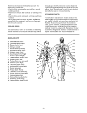
... for one minute after each set for a weight loss workout. Move slowly as you stretch and do not bounce. The chart on page 19 of every month. Sartorius (front of arm) B D. Rectus Abdominus (stomach) G M. Gluteus Maximus (buttocks) V. List the date, the exercises performed, the resistance used to 10 minutes of sets and repetitions completed. Pectoralis Major (chest) A C. Obliques (waist) E. Trapezius (upper back...
... for one minute after each set for a weight loss workout. Move slowly as you stretch and do not bounce. The chart on page 19 of every month. Sartorius (front of arm) B D. Rectus Abdominus (stomach) G M. Gluteus Maximus (buttocks) V. List the date, the exercises performed, the resistance used to 10 minutes of sets and repetitions completed. Pectoralis Major (chest) A C. Obliques (waist) E. Trapezius (upper back...
English Manual
Page 22
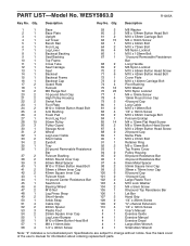
... back cover of the user's manual for information about ordering replacement parts. Qty. Description 1 1 Base 59 2 M8 Washer 2 1 Base Plate 60 2 M8 x 104mm Button Head Bolt 3 1 Upright 61 2 M10 x 53mm Carriage Bolt 4 1 Lat Tower 62 15 M4 x 16mm Screw 5 1 Bench Rail 63 1 M10 x 60mm Bolt 6 1 Front Leg 64 2 M10 x 72mm Bolt 7 1 Leg Lever 65 4 M8 Nylon Locknut 8 1 Backrest Backing 66 1 M10 x 103mm Bolt 9 1 Seat Backing 67 1 10-pound Removable Resistance 10...
... back cover of the user's manual for information about ordering replacement parts. Qty. Description 1 1 Base 59 2 M8 Washer 2 1 Base Plate 60 2 M8 x 104mm Button Head Bolt 3 1 Upright 61 2 M10 x 53mm Carriage Bolt 4 1 Lat Tower 62 15 M4 x 16mm Screw 5 1 Bench Rail 63 1 M10 x 60mm Bolt 6 1 Front Leg 64 2 M10 x 72mm Bolt 7 1 Leg Lever 65 4 M8 Nylon Locknut 8 1 Backrest Backing 66 1 M10 x 103mm Bolt 9 1 Seat Backing 67 1 10-pound Removable Resistance 10...
English Manual
Page 24
... by WEIDER 1500E resistance system) • the SERIAL NUMBER of the product (see the front cover of this manual) • the KEY NUMBER and DESCRIPTION of the part(s) (see the front cover of this warranty is shipped to a service center, freight charges to and from the date of purchase. ICON's obligation under normal use , costs of removal or installation or other warranties and any implied warranties of merchantability or fitness...
... by WEIDER 1500E resistance system) • the SERIAL NUMBER of the product (see the front cover of this manual) • the KEY NUMBER and DESCRIPTION of the part(s) (see the front cover of this warranty is shipped to a service center, freight charges to and from the date of purchase. ICON's obligation under normal use , costs of removal or installation or other warranties and any implied warranties of merchantability or fitness...

