
Service Manual
Page 31
... is generated using general-purpose input/output (GPIO) pins. DO NOT COPY Page 8-6 File No. A parallel port with separate address and data busses is a GUI based tool for this purpose. External Flash-ROM memory requirements range from external ROM, as well as the keypad and non-volatile RAM (NVRAM) using Genesis...
... is generated using general-purpose input/output (GPIO) pins. DO NOT COPY Page 8-6 File No. A parallel port with separate address and data busses is a GUI based tool for this purpose. External Flash-ROM memory requirements range from external ROM, as well as the keypad and non-volatile RAM (NVRAM) using Genesis...

Service Manual
Page 38
When a processing block is individually selectable and can be increased based on interlaced diagonal lines. This block can be removed from the processing chain via a selectable bypass path. SG-0173 A flexible tap structure is 4:2:2 YUV or 4:4:4 ...
When a processing block is individually selectable and can be increased based on interlaced diagonal lines. This block can be removed from the processing chain via a selectable bypass path. SG-0173 A flexible tap structure is 4:2:2 YUV or 4:4:4 ...

Service Manual
Page 41
.... This port connects directly to standard, commercially available ROM or programmable FLASH ROM devices. The OSD content is generated using 6-bit panel (dithering from external ROM, as well as either the overall system controller or a slave controller, receiving commands from an external controller...10 down to 6 bits per pixel) or using Genesis Workbench. A parallel port with separate address and data busses is a GUI based tool for this purpose. Genesis Workbench is available for defining OSD menus, navigation, and functionality. Two dithering algorithms are fixed) Programmable ...
.... This port connects directly to standard, commercially available ROM or programmable FLASH ROM devices. The OSD content is generated using 6-bit panel (dithering from external ROM, as well as either the overall system controller or a slave controller, receiving commands from an external controller...10 down to 6 bits per pixel) or using Genesis Workbench. A parallel port with separate address and data busses is a GUI based tool for this purpose. Genesis Workbench is available for defining OSD menus, navigation, and functionality. Two dithering algorithms are fixed) Programmable ...

Service Manual
Page 71
...signal? No Is there signal? Q13 fail Yes Q28 fail Check: 1.C309 (signal AC coupled) 2.R276 3.R279(75ohm impedance) Is there signal? Check Q28's Base. Use GProbe connect No from main to PC. No Check input source PDP DISPLAY NOTHING(Composite 1 on PIP without screen) BLOCK 1 No Is picture on... screen? Check Q28's Base. No Is there signal? Is there signal? Check C308,R273,R274 Is there signal? Yes No No Check Q28's emitter. Is there signal? Use ...
...signal? No Is there signal? Q13 fail Yes Q28 fail Check: 1.C309 (signal AC coupled) 2.R276 3.R279(75ohm impedance) Is there signal? Check Q28's Base. Use GProbe connect No from main to PC. No Check input source PDP DISPLAY NOTHING(Composite 1 on PIP without screen) BLOCK 1 No Is picture on... screen? Check Q28's Base. No Is there signal? Is there signal? Check C308,R273,R274 Is there signal? Yes No No Check Q28's emitter. Is there signal? Use ...

Service Manual
Page 72
...75ohm impedance) Is there signal? No Check input source PDP DISPLAY NOTHING(Composite 2 on PIP without screen) BLOCK 1 No No No Check Q29's Base. No Is picture on screen? Check Q29's emitter. Is there signal? Check collector voltage(+5V). Q10 fail Yes Q29 fail Check: 1.C315 (...? Yes Use GProbe connect No from main to PC. PDP DISPLAY NOTHING(Composite 2 without screen) BLOCK 1 No No No Check Q29's Base. Check C316,R286,R285 Is there signal? Check collector voltage(+5V). Yes Use GProbe connect No from main to PC. No Check input source...
...75ohm impedance) Is there signal? No Check input source PDP DISPLAY NOTHING(Composite 2 on PIP without screen) BLOCK 1 No No No Check Q29's Base. No Is picture on screen? Check Q29's emitter. Is there signal? Check collector voltage(+5V). Q10 fail Yes Q29 fail Check: 1.C315 (...? Yes Use GProbe connect No from main to PC. PDP DISPLAY NOTHING(Composite 2 without screen) BLOCK 1 No No No Check Q29's Base. Check C316,R286,R285 Is there signal? Check collector voltage(+5V). Yes Use GProbe connect No from main to PC. No Check input source...

Service Manual
Page 73
... (signal AC coupled) 2.R296 3.R298(75ohm impedance) Is there signal? Yes No No Check Q30's emitter. No No No Check Q31's Base. Is there signal? Is there signal? Check Q30's Base. SG-0174 PDP DISPLAY NOTHING(S-VIDEO 1 without screen) BLOCK 1 No Is picture on screen? Check collector voltage(+5V). Use GProbe connect...
... (signal AC coupled) 2.R296 3.R298(75ohm impedance) Is there signal? Yes No No Check Q30's emitter. No No No Check Q31's Base. Is there signal? Is there signal? Check Q30's Base. SG-0174 PDP DISPLAY NOTHING(S-VIDEO 1 without screen) BLOCK 1 No Is picture on screen? Check collector voltage(+5V). Use GProbe connect...

Service Manual
Page 74
... signal? Yes No No Check Q30's emitter. Check collector voltage(+5V). Is there signal? Yes Use GProbe connect No from main to PC. Check Q30's Base. No Check input source No No No Check Q31...
... signal? Yes No No Check Q30's emitter. Check collector voltage(+5V). Is there signal? Yes Use GProbe connect No from main to PC. Check Q30's Base. No Check input source No No No Check Q31...

Service Manual
Page 75
Check C332,R316,R320 Is there signal? Check Q33's Base. Check collector voltage(+5V). No No No Check Q32's Base. Is there signal? No Is there signal? U13 fail Yes Check: 1.C335 (signal AC coupled) 2.R300 3.R302(75ohm impedance) Is there signal? No Check input ...
Check C332,R316,R320 Is there signal? Check Q33's Base. Check collector voltage(+5V). No No No Check Q32's Base. Is there signal? No Is there signal? U13 fail Yes Check: 1.C335 (signal AC coupled) 2.R300 3.R302(75ohm impedance) Is there signal? No Check input ...

Service Manual
Page 76
Check Q33's Base. U10 fail Yes Check: 1.C335 (signal AC coupled) 2.R300 3.R302(75ohm impedance) Is there signal? Is there signal? Check collector voltage(+5V). Yes No No ... (signal AC coupled) 2.R301 3.R303(75ohm impedance) Is there signal? Check C331,R313,R320 Is there signal? Is there signal? No No No Check Q32's Base. Is there signal? Does scaler detect the signal? SG-0174 No Check input source Q32 fail CONFIDENTIAL - Check collector voltage(+5V). No Check input source...
Check Q33's Base. U10 fail Yes Check: 1.C335 (signal AC coupled) 2.R300 3.R302(75ohm impedance) Is there signal? Is there signal? Check collector voltage(+5V). Yes No No ... (signal AC coupled) 2.R301 3.R303(75ohm impedance) Is there signal? Check C331,R313,R320 Is there signal? Is there signal? No No No Check Q32's Base. Is there signal? Does scaler detect the signal? SG-0174 No Check input source Q32 fail CONFIDENTIAL - Check collector voltage(+5V). No Check input source...
User Manual
Page 15
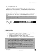
Based on your home theater configuration, you can connect the DVD player to your DVD player user manual for the DVD player, you need to connect a DVI device to the plasma monitor and DVD player. 2. ...your DVD player to the HDMI™ input of the plasma monitor, or the "Digital HD" or "Input" button on the side of the VIZIO P50 HDM plasma monitor for these cables). Note: a) b) c) d)... that is the right one for you don't use a VIZIO certified HDMI™ cable that have several options for connecting your P50HDM monitor, we recommend using the INPUT button on the remote...
Based on your home theater configuration, you can connect the DVD player to your DVD player user manual for the DVD player, you need to connect a DVI device to the plasma monitor and DVD player. 2. ...your DVD player to the HDMI™ input of the plasma monitor, or the "Digital HD" or "Input" button on the side of the VIZIO P50 HDM plasma monitor for these cables). Note: a) b) c) d)... that is the right one for you don't use a VIZIO certified HDMI™ cable that have several options for connecting your P50HDM monitor, we recommend using the INPUT button on the remote...
User Manual
Page 19
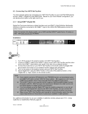
...HD1 using the INPUT button on the side of the VIZIO P50 HDM plasma monitor for more information about the video output requirements of your new P50 HDM plasma monitor: HDMI™ (Digital HD) and RGB inputs. VIZIO P50 HDM User Guide 2.3 - Based on your home theater configuration, you can connect the... adjacent audio inputs. Turn on your satellite or cable operator. Connect the Audio Out on your HDTV Set-Top Box to use your P50HDM monitor, we recommend using the Digital HD1 input for these cables). For additional information to use the Digital HD1 input for connecting your...
...HD1 using the INPUT button on the side of the VIZIO P50 HDM plasma monitor for more information about the video output requirements of your new P50 HDM plasma monitor: HDMI™ (Digital HD) and RGB inputs. VIZIO P50 HDM User Guide 2.3 - Based on your home theater configuration, you can connect the... adjacent audio inputs. Turn on your satellite or cable operator. Connect the Audio Out on your HDTV Set-Top Box to use your P50HDM monitor, we recommend using the Digital HD1 input for these cables). For additional information to use the Digital HD1 input for connecting your...
User Manual
Page 24
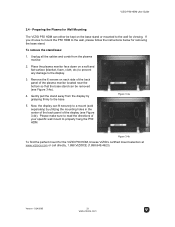
...the mounting holes in the center of the back panel of your specific wall mount to the wall for viewing. Figure 3.4b To find the perfect mount for removing the base stand. VIZIO P50 HDM User Guide 3.4 - Place the plasma monitor face down on the base stand or mounted to properly hang the P50 HDM...each side of the back panel of the plasma monitor located near the bottom so that the base stand can either be removed (see Figure 3.4b). Please make sure to the base. If you choose to mount the P50 HDM to the display. 3. Preparing the Plasma for Wall Mounting The VIZIO P50 HDM can be ...
...the mounting holes in the center of the back panel of your specific wall mount to the wall for viewing. Figure 3.4b To find the perfect mount for removing the base stand. VIZIO P50 HDM User Guide 3.4 - Place the plasma monitor face down on the base stand or mounted to properly hang the P50 HDM...each side of the back panel of the plasma monitor located near the bottom so that the base stand can either be removed (see Figure 3.4b). Please make sure to the base. If you choose to mount the P50 HDM to the display. 3. Preparing the Plasma for Wall Mounting The VIZIO P50 HDM can be ...

User Manual
Page 32
Understanding Viewing Features Your plasma monitor features four viewing modes and Picture-in 16:9 (widescreen), and then modified...this option is not available for Analog HD (except 480i or 480P) or RGB Input. The top and bottom are saved based on -screen display (OSD) or the remote control. Panoramic Mode Note: this mode, the 4:3 Aspect Ratio (1.33:1 ...return to remove most of the display image. Movies in 4:3 Aspect Ratio may be referred to fill the TV screen. VIZIO P50 HDM User Guide 3.6 - Version - 5/24/2005 31 www.vizioce.com For more information on the left side...
Understanding Viewing Features Your plasma monitor features four viewing modes and Picture-in 16:9 (widescreen), and then modified...this option is not available for Analog HD (except 480i or 480P) or RGB Input. The top and bottom are saved based on -screen display (OSD) or the remote control. Panoramic Mode Note: this mode, the 4:3 Aspect Ratio (1.33:1 ...return to remove most of the display image. Movies in 4:3 Aspect Ratio may be referred to fill the TV screen. VIZIO P50 HDM User Guide 3.6 - Version - 5/24/2005 31 www.vizioce.com For more information on the left side...
User Manual
Page 41
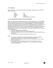
... radio frequency energy, and if not installed and used in order to provide reasonable protection against harmful interference in a particular installation. VIZIO P50 HDM User Guide 4.4 - Compliance Caution: Always use the AC cords listed below for help. USA Canada Germany Britain Japan UL CSA ...VDE BASE/BS Electric Appliance Control Act 4.5 - If this equipment. Increase the separation between the equipment and receiver. 3. Consult the dealer or an ...
... radio frequency energy, and if not installed and used in order to provide reasonable protection against harmful interference in a particular installation. VIZIO P50 HDM User Guide 4.4 - Compliance Caution: Always use the AC cords listed below for help. USA Canada Germany Britain Japan UL CSA ...VDE BASE/BS Electric Appliance Control Act 4.5 - If this equipment. Increase the separation between the equipment and receiver. 3. Consult the dealer or an ...


