Service Manual
Page 2
On Screen Display 4. Pin Assignment 6. Trouble Shooting 11. Main Board Circuit Diagram 2. Main Board PCB Layout 3. Features 2. Specifications 3. BLOCK DIAGRAM 7. Complete Parts List Appendix 1. Assembly Explosion Drawing Block Diagram PAGE 1-1 2-1 3-1 4-1 5-1 6-1 7-1 8-1 9-1 10-1 11-1 12-1 VIZIO P50HDM Service Manual Factory Preset Timings 5. Spare Parts List 12. Theory of Contents CONTENTS Sections 1. Waveforms 10. Table of Circuit Operation 9. Main Board I/O Connections 8.
On Screen Display 4. Pin Assignment 6. Trouble Shooting 11. Main Board Circuit Diagram 2. Main Board PCB Layout 3. Features 2. Specifications 3. BLOCK DIAGRAM 7. Complete Parts List Appendix 1. Assembly Explosion Drawing Block Diagram PAGE 1-1 2-1 3-1 4-1 5-1 6-1 7-1 8-1 9-1 10-1 11-1 12-1 VIZIO P50HDM Service Manual Factory Preset Timings 5. Spare Parts List 12. Theory of Contents CONTENTS Sections 1. Waveforms 10. Table of Circuit Operation 9. Main Board I/O Connections 8.
Service Manual
Page 20
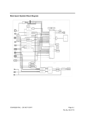
Main board System Block Diagram W8 CN17 U37 24LC02 EEPROM HDMI1 W13 U40 24LC02 EEPROM HDMI2 CN16 W6 Y Pr Pb Y Pr Pb W7 W11 W14 COMP1_Audio_R/L COMP2_Audio_R/L ...
Main board System Block Diagram W8 CN17 U37 24LC02 EEPROM HDMI1 W13 U40 24LC02 EEPROM HDMI2 CN16 W6 Y Pr Pb Y Pr Pb W7 W11 W14 COMP1_Audio_R/L COMP2_Audio_R/L ...
Service Manual
Page 21
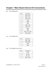
SG-0173 DO NOT COPY Page 7-1 File No. Chapter 7 Main Board Internal I/O Connections CN1 "DC POWER INPUT' PIN Description 1 PDP_+5Vsc 2 PDP_+5Vsc 3 PDP_+5Vsc 4 GND 5 GND 6 GND 7 PDP_+12V 8 PDP_+12V 9 GND 10 GND 11 PDP_+12V_FAN 12 PDP_FGND CN2 "DC POWER INPUT' PIN 1 2 3 4 Description PDP_Audio PDP_Audio GND GND CN3 "DC POWER INPUT/OUTPUT' PIN 1 2 3 4 Description GND VS_ON RLY_ON PDP_+5Vsb CONFIDENTIAL -
SG-0173 DO NOT COPY Page 7-1 File No. Chapter 7 Main Board Internal I/O Connections CN1 "DC POWER INPUT' PIN Description 1 PDP_+5Vsc 2 PDP_+5Vsc 3 PDP_+5Vsc 4 GND 5 GND 6 GND 7 PDP_+12V 8 PDP_+12V 9 GND 10 GND 11 PDP_+12V_FAN 12 PDP_FGND CN2 "DC POWER INPUT' PIN 1 2 3 4 Description PDP_Audio PDP_Audio GND GND CN3 "DC POWER INPUT/OUTPUT' PIN 1 2 3 4 Description GND VS_ON RLY_ON PDP_+5Vsb CONFIDENTIAL -
Service Manual
Page 61
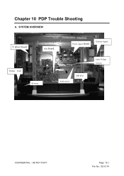
SG-0174 SYSTEM OVERVIEW Y driver board Main board Power supply board X driver board Display board IR board Audio power EMI filter Audio Voltage selectior CONFIDENTIAL - Chapter 10 PDP Trouble Shooting A. DO NOT COPY Page 10-1 File No.
SG-0174 SYSTEM OVERVIEW Y driver board Main board Power supply board X driver board Display board IR board Audio power EMI filter Audio Voltage selectior CONFIDENTIAL - Chapter 10 PDP Trouble Shooting A. DO NOT COPY Page 10-1 File No.
Service Manual
Page 62
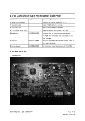
... No. PCB PARTS NAME/NUMBER AND FUNCTION DESCRIPTION PART NAME PART NUMBER POWER SUPPLY BOARD X DRIVER BOARD Y DRIVER BOARD AUDIO POWER SELECTOR MAIN BOARD 385000120150 IR BOARD DISPLAY BOARD 385000120189 385000120156 FUNCTION DESCRIPTION PROVIDE ALL THE POWER FOR TV SET X ELECTRODE DRIVING BOARD Y ELECTRODE DRIVING BOARD AUDIO POWER SUPPLY(+30V OR +24V) CONNECTING TO TRANSFER DISPLY SIGNAL TO PDP...
... No. PCB PARTS NAME/NUMBER AND FUNCTION DESCRIPTION PART NAME PART NUMBER POWER SUPPLY BOARD X DRIVER BOARD Y DRIVER BOARD AUDIO POWER SELECTOR MAIN BOARD 385000120150 IR BOARD DISPLAY BOARD 385000120189 385000120156 FUNCTION DESCRIPTION PROVIDE ALL THE POWER FOR TV SET X ELECTRODE DRIVING BOARD Y ELECTRODE DRIVING BOARD AUDIO POWER SUPPLY(+30V OR +24V) CONNECTING TO TRANSFER DISPLY SIGNAL TO PDP...
Service Manual
Page 64
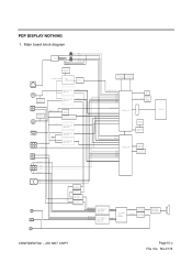
SG-0174 Main board block diagram U26 MAX232A J9 2 1 3 J10 2 1 3 ATXD_HUD ARXD_HUD U40 24LC128 EEPROM(8051) ARXD ATXD_HUD ATXD ARXD_HUD UC_SCL/UC_SDA U38 SM5964-C40J U20 4052 4/1 x2 I/O HY5DU56822CT-...
SG-0174 Main board block diagram U26 MAX232A J9 2 1 3 J10 2 1 3 ATXD_HUD ARXD_HUD U40 24LC128 EEPROM(8051) ARXD ATXD_HUD ATXD ARXD_HUD UC_SCL/UC_SDA U38 SM5964-C40J U20 4052 4/1 x2 I/O HY5DU56822CT-...
Service Manual
Page 65
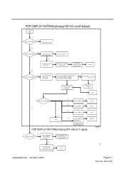
...is lighting? Yes Press Meun or Info. Check internal cable? 1.CN1's cable 2.CN3's cable No Check main board CN3 pin 4Î studyby +5V Check CN3 pin 3Î RLY_ON(high) Check CN3 pin 2Î VS_ON... Fuse open? (F2,F3,F4) Yse Check CN1Îpin 1,2,3 = +5V pin 7,8 = +12V No Yes Panel power fail No Fuse fail D10,D11 LED is lighting? Check component 1 No (Y signal) ÎC252 Is there ... Trace componect 1 from Input To U13 circuit Check R190,R191 Yes 1 Use GProbe connect No from main to PC. Does scaler detect the signal? PDP DISPLAY NOTHING(Analog HD1/AC on screen? Yes No ...
...is lighting? Yes Press Meun or Info. Check internal cable? 1.CN1's cable 2.CN3's cable No Check main board CN3 pin 4Î studyby +5V Check CN3 pin 3Î RLY_ON(high) Check CN3 pin 2Î VS_ON... Fuse open? (F2,F3,F4) Yse Check CN1Îpin 1,2,3 = +5V pin 7,8 = +12V No Yes Panel power fail No Fuse fail D10,D11 LED is lighting? Check component 1 No (Y signal) ÎC252 Is there ... Trace componect 1 from Input To U13 circuit Check R190,R191 Yes 1 Use GProbe connect No from main to PC. Does scaler detect the signal? PDP DISPLAY NOTHING(Analog HD1/AC on screen? Yes No ...


