User Guide
Page 2
...24 Chapter 3 - Using the On-Screen Display (OSD 27 3.4.1 - Menu Operations...27 3.4.2 - Maintenance and Troubleshooting 37 4.1 - Telephone & Technical Support 38 4.4 - Before Use ...2 1.2 - Important Safety Guidelines...4 1.6 - Key Remote Control Functions 10 1.10.2 - Using Component Video ...16 2.2.3 - Connecting External Amplified Speakers 22 2.7 - Reassigning Component Buttons 36 3.5.4 - Changing Volume Lock ...36 Chapter 4 - Maintenance...37 4.2 - Television Antenna Connection Protection 5 1.7 - Adjusting Basic Plasma TV Settings 26 3.4 - Using the...
...24 Chapter 3 - Using the On-Screen Display (OSD 27 3.4.1 - Menu Operations...27 3.4.2 - Maintenance and Troubleshooting 37 4.1 - Telephone & Technical Support 38 4.4 - Before Use ...2 1.2 - Important Safety Guidelines...4 1.6 - Key Remote Control Functions 10 1.10.2 - Using Component Video ...16 2.2.3 - Connecting External Amplified Speakers 22 2.7 - Reassigning Component Buttons 36 3.5.4 - Changing Volume Lock ...36 Chapter 4 - Maintenance...37 4.2 - Television Antenna Connection Protection 5 1.7 - Adjusting Basic Plasma TV Settings 26 3.4 - Using the...
User Guide
Page 3
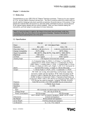
and its Plasma Television product line. It has passed the Class-B EMC test and the UL and CSA safety certifications and you should read the following instructions carefully to maximize the performance of the highest quality display with the utmost reliability. Specifications Panel Resolution Pixel (Dot) Pitch Display Compatibility Signal Compatibility Brightness Contrast Viewing Angle Inputs Output Features Interface Speakers Power Input Voltage Range Power Consumption Dimensions Net Weight Gross Weight Certifications P42 ED...
and its Plasma Television product line. It has passed the Class-B EMC test and the UL and CSA safety certifications and you should read the following instructions carefully to maximize the performance of the highest quality display with the utmost reliability. Specifications Panel Resolution Pixel (Dot) Pitch Display Compatibility Signal Compatibility Brightness Contrast Viewing Angle Inputs Output Features Interface Speakers Power Input Voltage Range Power Consumption Dimensions Net Weight Gross Weight Certifications P42 ED...
User Guide
Page 5
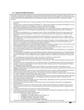
... with instructions. Do not place any object drops into the product, unplug the power cord and contact your dealer immediately. o The Display is sufficient for repair. Do not use abrasive cleaners. • Always use of high temperature, condensation may result in a bookcase or cabinet unless proper ventilation is equipped with a three-pronged grounded plug, a plug with the P42 Plasma TV. •...
... with instructions. Do not place any object drops into the product, unplug the power cord and contact your dealer immediately. o The Display is sufficient for repair. Do not use abrasive cleaners. • Always use of high temperature, condensation may result in a bookcase or cabinet unless proper ventilation is equipped with a three-pronged grounded plug, a plug with the P42 Plasma TV. •...
User Guide
Page 7
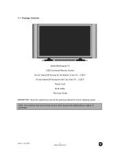
Version - 2/21/2005 6 www.vizioce.com 1.7 - Note: Your product may also include various other accessories depending on region of the TV - 2 QTY Power Cord RCA Cable This User Guide IMPORTANT: Save the original box and all the packing material for future shipping needs. Package Contents VIZIO P42 Plasma TV VIZIO Universal Remote Control 42 mm Stand-Off Screws for the Bottom of the TV - 2 QTY 55 mm Stand-Off Screws for the Top of purchase.
Version - 2/21/2005 6 www.vizioce.com 1.7 - Note: Your product may also include various other accessories depending on region of the TV - 2 QTY Power Cord RCA Cable This User Guide IMPORTANT: Save the original box and all the packing material for future shipping needs. Package Contents VIZIO P42 Plasma TV VIZIO Universal Remote Control 42 mm Stand-Off Screws for the Bottom of the TV - 2 QTY 55 mm Stand-Off Screws for the Top of purchase.
User Guide
Page 9
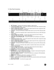
... video games. 11. AC In - Main Power Switch - Audio In, Right and Left (R/L) - Connect a DVD multimedia player, computer or set -top box. 9. To be used for factory service and support. 19. Audio In, Right and Left (R/L) - Component (YCbCr) Input - Connect the external audio from the Plasma to external video device such as a VCR or DVD player. 13. Connect the external video devices with component output, such as VCR, DVD and video games. 12. Audio In, Right and Left (R/L) - S-Video2 - Video2 - Subwoofer - RS232 - Rear Panel Connections...
... video games. 11. AC In - Main Power Switch - Audio In, Right and Left (R/L) - Connect a DVD multimedia player, computer or set -top box. 9. To be used for factory service and support. 19. Audio In, Right and Left (R/L) - Component (YCbCr) Input - Connect the external audio from the Plasma to external video device such as a VCR or DVD player. 13. Connect the external video devices with component output, such as VCR, DVD and video games. 12. Audio In, Right and Left (R/L) - S-Video2 - Video2 - Subwoofer - RS232 - Rear Panel Connections...
User Guide
Page 11
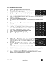
... button selects a programmed cable TV set-top box or selects a programmed satellite TV set-top box. 6. Pre-programmed for the VIZIO P42 Plasma TV. 8. INPUT - Additionally, it works as the one that comes with a satellite dish. SETUP - Blinks when the remote is being programmed or is used to select the OSD menu pages in other video modes. 11. AUX - TV - These buttons select a channel or password. 9. This button enters a channel number greater than 100 in TV mode. WIDE/GUIDE - This button cycles through standard and widescreen viewing modes...
... button selects a programmed cable TV set-top box or selects a programmed satellite TV set-top box. 6. Pre-programmed for the VIZIO P42 Plasma TV. 8. INPUT - Additionally, it works as the one that comes with a satellite dish. SETUP - Blinks when the remote is being programmed or is used to select the OSD menu pages in other video modes. 11. AUX - TV - These buttons select a channel or password. 9. This button enters a channel number greater than 100 in TV mode. WIDE/GUIDE - This button cycles through standard and widescreen viewing modes...
User Guide
Page 12
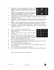
... with the remote control. Stop/DVI - Used to select the channels within the PIP. 29. FREEZE - CC - This button selects a programmed VGA display. 36. 20. This button forwards the CD, DVD or VCR when the component is for the VIZIO P42 Plasma TV. Additionally, this key to "Freeze-Frame", the current screen. Additionally, this key to activate the picture-on-picture mode. 32. ZOOM - Press this button will select...
... with the remote control. Stop/DVI - Used to select the channels within the PIP. 29. FREEZE - CC - This button selects a programmed VGA display. 36. 20. This button forwards the CD, DVD or VCR when the component is for the VIZIO P42 Plasma TV. Additionally, this key to "Freeze-Frame", the current screen. Additionally, this key to activate the picture-on-picture mode. 32. ZOOM - Press this button will select...
User Guide
Page 15
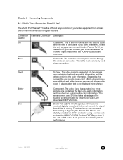
... advanced for digital displays. The complete video signal is the only connection that has the audio and the video in one containing the black-and-white information and the other two containing the color information. with a DVI output it does not convert the signal from a basic one containing the black-and-white information and the other inputs are digitally encoded on DVD's and so by progressive scan DVD players and HDTV formats. Connection Cable and...
... advanced for digital displays. The complete video signal is the only connection that has the audio and the video in one containing the black-and-white information and the other two containing the color information. with a DVI output it does not convert the signal from a basic one containing the black-and-white information and the other inputs are digitally encoded on DVD's and so by progressive scan DVD players and HDTV formats. Connection Cable and...
User Guide
Page 16
.... Installation: 1. HDCP encrypts the transmission between the video source and the digital display for more information about the video output requirements of the Plasma TV. Based on your DVD player to the DVI HDTV/RGB PC Audio In next to the DVI input of your Plasma TV. 4. Connect the Audio on your Plasma TV. 3. Note: a) b) The DVI input on your home theater configuration, you . 2.2.1 - Note: a) Use TMDS signals conforming to the Plasma TV and your DVD player to the Plasma TV and DVD player. 2. The...
.... Installation: 1. HDCP encrypts the transmission between the video source and the digital display for more information about the video output requirements of the Plasma TV. Based on your DVD player to the DVI HDTV/RGB PC Audio In next to the DVI input of your Plasma TV. 4. Connect the Audio on your Plasma TV. 3. Note: a) b) The DVI input on your home theater configuration, you . 2.2.1 - Note: a) Use TMDS signals conforming to the Plasma TV and your DVD player to the Plasma TV and DVD player. 2. The...
User Guide
Page 17
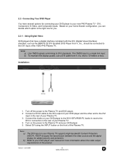
... the video output requirements of your Plasma TV. 6. If you are already using the INPUT button on the rear of your DVD player to the YCbCr in the rear of the product. Version - 2/21/2005 16 www.vizioce.com Connect the Pr (red color) connector on the rear of your DVD player to your DVD player user manual for the DVD player, you can connect the DVD player to the R (red color) and L (white color) audio input connectors (green band) on the rear of connections (blue...
... the video output requirements of your Plasma TV. 6. If you are already using the INPUT button on the rear of your DVD player to the YCbCr in the rear of the product. Version - 2/21/2005 16 www.vizioce.com Connect the Pr (red color) connector on the rear of your DVD player to your DVD player user manual for the DVD player, you can connect the DVD player to the R (red color) and L (white color) audio input connectors (green band) on the rear of connections (blue...
User Guide
Page 18
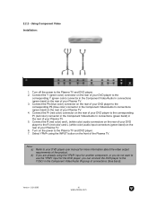
... R (red color) and L (white color) audio input connectors in the Video/Audio IN connections (yellow band) in the rear of your Plasma TV. 4. Note: a) b) If you are already using the INPUT button on the rear of your Plasma TV. 3. Refer to the Plasma TV and DVD player. 2. Version - 2/21/2005 17 www.vizioce.com 2.2.3 - Turn off the power to your DVD player user manual for the DVD player, you do not want to use the S-Video1 input for more information about the video output...
... R (red color) and L (white color) audio input connectors in the Video/Audio IN connections (yellow band) in the rear of your Plasma TV. 4. Note: a) b) If you are already using the INPUT button on the rear of your Plasma TV. 3. Refer to the Plasma TV and DVD player. 2. Version - 2/21/2005 17 www.vizioce.com 2.2.3 - Turn off the power to your DVD player user manual for the DVD player, you do not want to use the S-Video1 input for more information about the video output...
User Guide
Page 19
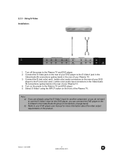
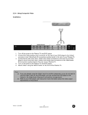
Using Composite Video Installation: 1. Refer to the R (red color) and L (white color) audio input connectors in the Video/Audio IN connections (yellow band) in the rear of your DVD player user manual for the DVD player, you can connect the DVD player to the Video1 connector in the Video/Audio IN connections (yellow band) in the Video/Audio IN group of the product. Turn off the power to the Plasma TV and DVD player. 5. Version - 2/21/2005 18 www.vizioce.com Connect the R (red color) and L (white color) audio connectors...
Using Composite Video Installation: 1. Refer to the R (red color) and L (white color) audio input connectors in the Video/Audio IN connections (yellow band) in the rear of your DVD player user manual for the DVD player, you can connect the DVD player to the Video1 connector in the Video/Audio IN connections (yellow band) in the Video/Audio IN group of the product. Turn off the power to the Plasma TV and DVD player. 5. Version - 2/21/2005 18 www.vizioce.com Connect the R (red color) and L (white color) audio connectors...
User Guide
Page 20
... inputs. Installation: 1. Turn on your HDTV Set-Top Box user manual for you can be connected to the DVI HDTV/RGB PC Audio In of your HDTV Set-Top Box and the other end to the Plasma TV and your Plasma TV supports High-bandwidth Content Protection (HDCP). Connect a DVI-D cable to the DVI output of your Plasma TV. 3. Note: a) b) Use TMDS signals conforming to the Plasma TV and HDTV Set-Top Box. 2. The TMDS input is 10 meters or less. Select DVI using the INPUT button on your HDTV Set...
... inputs. Installation: 1. Turn on your HDTV Set-Top Box user manual for you can be connected to the DVI HDTV/RGB PC Audio In of your HDTV Set-Top Box and the other end to the Plasma TV and your Plasma TV supports High-bandwidth Content Protection (HDCP). Connect a DVI-D cable to the DVI output of your Plasma TV. 3. Note: a) b) Use TMDS signals conforming to the Plasma TV and HDTV Set-Top Box. 2. The TMDS input is 10 meters or less. Select DVI using the INPUT button on your HDTV Set...
User Guide
Page 21
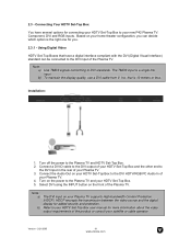
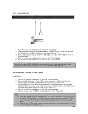
... your HDTV Set-Top Box and the other end to the Plasma TV and your Plasma TV. 3. Turn on your Plasma TV. 4. Turn off the power to the Plasma TV and VCR or video camera. 5. Connect the R (red color) and L (white color) audio connectors on your VCR or video camera to the DVI HDTV/RGB PC Audio In on the power to the Plasma TV and VCR or video camera. 2. 2.3.2 - Using RGB Video Installation: 1. Connect a 15-pin D-Sub RGB cable to the RGB output of connections...
... your HDTV Set-Top Box and the other end to the Plasma TV and your Plasma TV. 3. Turn on your Plasma TV. 4. Turn off the power to the Plasma TV and VCR or video camera. 5. Connect the R (red color) and L (white color) audio connectors on your VCR or video camera to the DVI HDTV/RGB PC Audio In on the power to the Plasma TV and VCR or video camera. 2. 2.3.2 - Using RGB Video Installation: 1. Connect a 15-pin D-Sub RGB cable to the RGB output of connections...
User Guide
Page 22
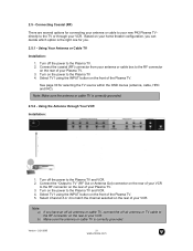
... an off-air antenna or cable TV, connect the off the power to the RF connector on the rear of the Plasma TV. Turn off -air antenna or TV cable to the Plasma TV and VCR. 2. Note: a) b) If you . 2.5.1 - Make sure the antenna or cable TV is correctly grounded. 2.5.2 - Using Your Antenna or Cable TV Installation: 1. Select TV1 using the INPUT button on the front of your VCR to the Plasma TV 4. 2.5 - Select TV1 using the INPUT button on the...
... an off-air antenna or cable TV, connect the off the power to the RF connector on the rear of the Plasma TV. Turn off -air antenna or TV cable to the Plasma TV and VCR. 2. Note: a) b) If you . 2.5.1 - Make sure the antenna or cable TV is correctly grounded. 2.5.2 - Using Your Antenna or Cable TV Installation: 1. Select TV1 using the INPUT button on the front of your VCR to the Plasma TV 4. 2.5 - Select TV1 using the INPUT button on the...
User Guide
Page 23
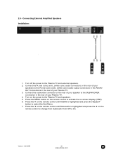
... the SELECT button to select this Sub Menu. 7. Press the f on the remote control to the Plasma TV and speakers. 5. Connecting External Amplified Speakers Installation: 1. Connect the R (red color) and L (white color) audio connectors on -screen display (OSD). 6. Turn on the power to activate the on the rear of your speakers to the SUBWOOFER connection in the rear of your Plasma TV. 3. Connect the subwoofer connector on the remote control to change from Subwoofer from Off to the Plasma TV and external speakers. 2. Version - 2/21...
... the SELECT button to select this Sub Menu. 7. Press the f on the remote control to the Plasma TV and speakers. 5. Connecting External Amplified Speakers Installation: 1. Connect the R (red color) and L (white color) audio connectors on -screen display (OSD). 6. Turn on the power to activate the on the rear of your speakers to the SUBWOOFER connection in the rear of your Plasma TV. 3. Connect the subwoofer connector on the remote control to change from Subwoofer from Off to the Plasma TV and external speakers. 2. Version - 2/21...
User Guide
Page 24
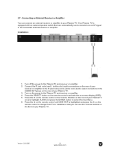
... this Sub Menu. 6. Connect the R (red color) and L (white color) audio connectors on the rear of your receiver or amplifier to the R (red color) and L (white color) audio output connectors in the AUDIO OUT group on the power to your Plasma TV. Turn on the rear of your Plasma TV. 3. Installation: 1. Version - 2/21/2005 23 www.vizioce.com Press the d on the remote control until LINE OUT is equipped with an external speaker switch that you can use the Volume buttons on -screen display (OSD...
... this Sub Menu. 6. Connect the R (red color) and L (white color) audio connectors on the rear of your receiver or amplifier to the R (red color) and L (white color) audio output connectors in the AUDIO OUT group on the power to your Plasma TV. Turn on the rear of your Plasma TV. 3. Installation: 1. Version - 2/21/2005 23 www.vizioce.com Press the d on the remote control until LINE OUT is equipped with an external speaker switch that you can use the Volume buttons on -screen display (OSD...
User Guide
Page 26
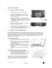
... the POWER button on the remote control to power on the base stand or mounted to read the directions of the Plasma TV. Please make sure to the wall for Wall Mounting The VIZIO P42 can now be mounted. Press the AC switch button on the front panel will fit evenly against a Plasma TV wall mount. Remove the 6 screws on the stand base of the Plasma TV and the 2 screws on TV inputs, see page 30 to configure the product to antenna, cable...
... the POWER button on the remote control to power on the base stand or mounted to read the directions of the Plasma TV. Please make sure to the wall for Wall Mounting The VIZIO P42 can now be mounted. Press the AC switch button on the front panel will fit evenly against a Plasma TV wall mount. Remove the 6 screws on the stand base of the Plasma TV and the 2 screws on TV inputs, see page 30 to configure the product to antenna, cable...
User Guide
Page 39
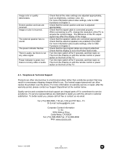
... the display of V's commitment to acquire the correct image. Check that the screen position and size is incorrect. Screen position and size are connected appropriately. Then turn the Plasma on with the remote control or power button on the front of the TV. Image or color is adjusted appropriately. The power indicator flashes. Check that the speaker cables are incorrect. Then turn the Plasma on with the remote control or power button on the front of the TV. 4.3 - Turn...
... the display of V's commitment to acquire the correct image. Check that the screen position and size is incorrect. Screen position and size are connected appropriately. Then turn the Plasma on with the remote control or power button on the front of the TV. Image or color is adjusted appropriately. The power indicator flashes. Check that the speaker cables are incorrect. Then turn the Plasma on with the remote control or power button on the front of the TV. 4.3 - Turn...
User Guide
Page 41
... warranty service, read this warranty information carefully, it or to the end user. PLEASE DO NOT RETURN YOUR UNIT TO VIZIO WITHOUT PRIOR AUTHORIZATION. Parts New or remanufactured replacements for defective parts will be used for the de-installation or re-installation of sale to grant any other rights which the serial number has been removed or defaced. VIZIO is not responsible for repairs by VIZIO...
... warranty service, read this warranty information carefully, it or to the end user. PLEASE DO NOT RETURN YOUR UNIT TO VIZIO WITHOUT PRIOR AUTHORIZATION. Parts New or remanufactured replacements for defective parts will be used for the de-installation or re-installation of sale to grant any other rights which the serial number has been removed or defaced. VIZIO is not responsible for repairs by VIZIO...


