Maintenance Manual
Page 3
... instruction is not observed. If a screw is not observed. SAFETY PRECAUTIONS Four types of messages are used in this manual to bring important information to your safe maintenance service. WARNING: "Warning" indicates the existence of these messages will be sure to use only the same model battery or an equivalent battery recommended by Toshiba. Installation of a short circuit, which could result in safety hazards. Satellite A110/Satellite Pro A110 Series Maintenance Manual...
... instruction is not observed. If a screw is not observed. SAFETY PRECAUTIONS Four types of messages are used in this manual to bring important information to your safe maintenance service. WARNING: "Warning" indicates the existence of these messages will be sure to use only the same model battery or an equivalent battery recommended by Toshiba. Installation of a short circuit, which could result in safety hazards. Satellite A110/Satellite Pro A110 Series Maintenance Manual...
Maintenance Manual
Page 4
... removal and replacement of the FRUs. Appendices The appendices describe the following parts: Chapter 1 Hardware Overview describes the Satellite A110/Satellite Pro A110 Series system unit and each FRU. Chapter 2 Troubleshooting Procedures explains how to diagnose and resolve FRU problems. Chapter 3 Test and Diagnostics describes how to perform test and diagnostic operations for maintenance service. The manual is divided into the following : ‰ Handling the LCD module ‰ Board...
... removal and replacement of the FRUs. Appendices The appendices describe the following parts: Chapter 1 Hardware Overview describes the Satellite A110/Satellite Pro A110 Series system unit and each FRU. Chapter 2 Troubleshooting Procedures explains how to diagnose and resolve FRU problems. Chapter 3 Test and Diagnostics describes how to perform test and diagnostic operations for maintenance service. The manual is divided into the following : ‰ Handling the LCD module ‰ Board...
Maintenance Manual
Page 17
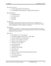
...; Optional devices • DVD-ROM module • Li-Ion Battery pack • AC adapter • HDD pack ‰ Keyboard The computer's keyboard has 101/102 keys and the layouts are five types of keys: typewriter keys, keypad overlay, function keys, soft keys, and cursor control keys. ‰ TouchPad This pointing control device, located in 1 Card reader (BTO) • Kensington lock Detroit 20 /Detroit 20E Series Maintenance Manual [CONFIDENTIAL] 1-3 There are compatible with LED indicator • One Express Card slot (BTO) • One Microphone jack •...
...; Optional devices • DVD-ROM module • Li-Ion Battery pack • AC adapter • HDD pack ‰ Keyboard The computer's keyboard has 101/102 keys and the layouts are five types of keys: typewriter keys, keypad overlay, function keys, soft keys, and cursor control keys. ‰ TouchPad This pointing control device, located in 1 Card reader (BTO) • Kensington lock Detroit 20 /Detroit 20E Series Maintenance Manual [CONFIDENTIAL] 1-3 There are compatible with LED indicator • One Express Card slot (BTO) • One Microphone jack •...

Maintenance Manual
Page 19
... port supporting DDC 2B enables connection of an external monitor, which is recognized automatically by Video Electronics Standards Association (VESA) Display Data Channel (DDC) compatible functions. ‰ Sound system Windows® Operating System compatible sound system provides internal speakers as well as jacks for output of NTSC or PAL signal. Detroit 20 /Detroit 20E Series Maintenance Manual [CONFIDENTIAL] 1-5 Bluetooth is a short-range wireless technology used to create PANs (Personal Area Networks) among your devices...
... port supporting DDC 2B enables connection of an external monitor, which is recognized automatically by Video Electronics Standards Association (VESA) Display Data Channel (DDC) compatible functions. ‰ Sound system Windows® Operating System compatible sound system provides internal speakers as well as jacks for output of NTSC or PAL signal. Detroit 20 /Detroit 20E Series Maintenance Manual [CONFIDENTIAL] 1-5 Bluetooth is a short-range wireless technology used to create PANs (Personal Area Networks) among your devices...
Maintenance Manual
Page 34
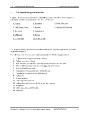
Display 6. USB Floppy Drive 7. Wireless LAN system 3. Modem 5. Cleaning kit for floppy disk drive testing 5. External monitor 10. USB test module and USB cable 14. PCMCIA unit The Diagnostics Disk operations are given in Chapter 3. Detailed replacement procedures are described in Chapter 4. Sycard (PCMCIA test card) 6. USB compatible keyboard 11. USB ports 9. Diagnostics Disk (Repair and Sound Repair) 2. Multimedia sound system with line-in the computer is causing the computer to determine if a Field Replaceable Unit (FRU) in...
Display 6. USB Floppy Drive 7. Wireless LAN system 3. Modem 5. Cleaning kit for floppy disk drive testing 5. External monitor 10. USB test module and USB cable 14. PCMCIA unit The Diagnostics Disk operations are given in Chapter 3. Detailed replacement procedures are described in Chapter 4. Sycard (PCMCIA test card) 6. USB compatible keyboard 11. USB ports 9. Diagnostics Disk (Repair and Sound Repair) 2. Multimedia sound system with line-in the computer is causing the computer to determine if a Field Replaceable Unit (FRU) in...
Maintenance Manual
Page 40
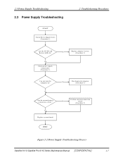
...Replace system board Y es Run diagnostic program (Procedure 4) Perform internal connection No check (Procedure 5) END Figure 2-2 Power Supply Troubleshooting Process Satellite A110 /Satellite Pro A110 Series Maintenance Manual [CONFIDENTIAL] 2-7 Y es Check power supply connections (Procedure 3) No Replace adaptor / battery (Procedure 2) Can you turn the computer on? 2.3 Power Supply Troubleshooting 2.3 Power Supply Troubleshooting START Check Power Supply Status (Procedure 1) 2 Troubleshooting Procedures Are the DC-IN and Battery LEDs lit? No Are the internal power connections...
...Replace system board Y es Run diagnostic program (Procedure 4) Perform internal connection No check (Procedure 5) END Figure 2-2 Power Supply Troubleshooting Process Satellite A110 /Satellite Pro A110 Series Maintenance Manual [CONFIDENTIAL] 2-7 Y es Check power supply connections (Procedure 3) No Replace adaptor / battery (Procedure 2) Can you turn the computer on? 2.3 Power Supply Troubleshooting 2.3 Power Supply Troubleshooting START Check Power Supply Status (Procedure 1) 2 Troubleshooting Procedures Are the DC-IN and Battery LEDs lit? No Are the internal power connections...

Maintenance Manual
Page 43
Check 6 Make sure the battery pack is properly installed and the battery LED still does not light, go to Check 5. If the battery is installed in the computer correctly. If there is several percent lower than 19 V, go to Procedure 4. 2-10 [CONFIDENTIAL] Satellite A110/Satellite Pro A110 Series Maintenance Manual If the output is no damage, go to Check 4. If the power cord is not loose, go to...
Check 6 Make sure the battery pack is properly installed and the battery LED still does not light, go to Check 5. If the battery is installed in the computer correctly. If there is several percent lower than 19 V, go to Procedure 4. 2-10 [CONFIDENTIAL] Satellite A110/Satellite Pro A110 Series Maintenance Manual If the output is no damage, go to Check 4. If the power cord is not loose, go to...

Maintenance Manual
Page 44
... in Chapter 4, Replacement Procedures. If no problem is detected, the battery is connected firmly, go to Check 3. If you cannot turn on the system board are not blown. If it with a new one following the procedures described in Chapter 4. Procedure 5 Replacement check The system board may be disconnected or damaged. Disassemble the computer following procedures: 1. Satellite A110 /Satellite Pro A110 Series Maintenance Manual [CONFIDENTIAL] 2-11 2.3 Power Supply Troubleshooting 2 Troubleshooting Procedures Procedure...
... in Chapter 4, Replacement Procedures. If no problem is detected, the battery is connected firmly, go to Check 3. If you cannot turn on the system board are not blown. If it with a new one following the procedures described in Chapter 4. Procedure 5 Replacement check The system board may be disconnected or damaged. Disassemble the computer following procedures: 1. Satellite A110 /Satellite Pro A110 Series Maintenance Manual [CONFIDENTIAL] 2-11 2.3 Power Supply Troubleshooting 2 Troubleshooting Procedures Procedure...
Maintenance Manual
Page 46
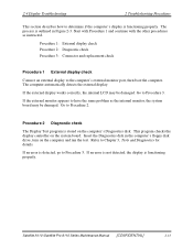
... the display controller on the system board. If the external display works correctly, the internal LCD may be damaged. Insert the Diagnostics disk in Figure 2-3. If the external monitor appears to have the same problem as instructed. Satellite A110 /Satellite Pro A110 Series Maintenance Manual [CONFIDENTIAL] 2-13 Start with Procedure 1 and continue with the other procedures as the internal monitor, the system board may be damaged. Go to the computer's external monitor port, then boot the computer. If an error...
... the display controller on the system board. If the external display works correctly, the internal LCD may be damaged. Insert the Diagnostics disk in Figure 2-3. If the external monitor appears to have the same problem as instructed. Satellite A110 /Satellite Pro A110 Series Maintenance Manual [CONFIDENTIAL] 2-13 Start with Procedure 1 and continue with the other procedures as the internal monitor, the system board may be damaged. Go to the computer's external monitor port, then boot the computer. If an error...
Maintenance Manual
Page 49
...] Satellite A110/Satellite Pro A110 Series Maintenance Manual Replace it with a new one following procedures. Refer to Chapter 3, Tests and Diagnostics for more information on how to Procedure 3. Disassemble the computer following the steps described in Chapter 4, Replacement Procedures and perform the following the instructions in Chapter 4. If the connection is functioning properly. If there is located, go to Procedure 2. Go to Check 2. Check 1 Make sure the keyboard cable...
...] Satellite A110/Satellite Pro A110 Series Maintenance Manual Replace it with a new one following procedures. Refer to Chapter 3, Tests and Diagnostics for more information on how to Procedure 3. Disassemble the computer following the steps described in Chapter 4, Replacement Procedures and perform the following the instructions in Chapter 4. If the connection is functioning properly. If there is located, go to Procedure 2. Go to Check 2. Check 1 Make sure the keyboard cable...
Maintenance Manual
Page 51
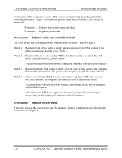
...'s external USB devices are three in Chapter 4. 2-18 [CONFIDENTIAL] Satellite A110/Satellite Pro A110 Series Maintenance Manual Replace it with Procedure 1 and continue as the original device, the system board may be damaged and should be damaged. If the device functions correctly when connected to have the same problem as instructed. Check 2 Plug the USB device into one following procedures. If the alternative USB device works correctly, the original device may be damaged. Check 1 Make sure USB device cable...
...'s external USB devices are three in Chapter 4. 2-18 [CONFIDENTIAL] Satellite A110/Satellite Pro A110 Series Maintenance Manual Replace it with Procedure 1 and continue as the original device, the system board may be damaged and should be damaged. If the device functions correctly when connected to have the same problem as instructed. Check 2 Plug the USB device into one following procedures. If the alternative USB device works correctly, the original device may be damaged. Check 1 Make sure USB device cable...
Maintenance Manual
Page 57
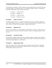
... in turn the audio board and system board. 2-24 [CONFIDENTIAL] Satellite A110/Satellite Pro A110 Series Maintenance Manual Start with Procedure 2. If they do not work properly, try replacing in Chapter 4, Replacement Procedures and make sure the speaker cable is in speakers are still not functioning properly, go to the audio board. Procedure 2 Earphone test Connect a set if earphones or external speakers. If not all have sound problem, the problem is firmly connected to Procedure 3. First adjust the speaker volume...
... in turn the audio board and system board. 2-24 [CONFIDENTIAL] Satellite A110/Satellite Pro A110 Series Maintenance Manual Start with Procedure 2. If they do not work properly, try replacing in Chapter 4, Replacement Procedures and make sure the speaker cable is in speakers are still not functioning properly, go to the audio board. Procedure 2 Earphone test Connect a set if earphones or external speakers. If not all have sound problem, the problem is firmly connected to Procedure 3. First adjust the speaker volume...
Maintenance Manual
Page 59
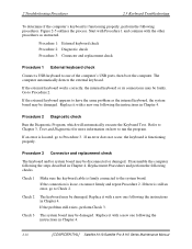
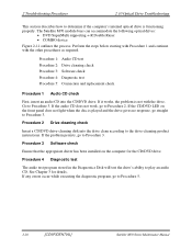
... Procedure 2: Drive cleaning check Procedure 3: Software check Procedure 4: Diagnostic test Procedure 5: Connection and replacement check Procedure 1 Audio CD check First, insert an audio CD into the drive clean according to the drive-cleaning product instructions. If the CD/DVD LED on the computer for details. Procedure 3 Software check Ensure that the appropriate driver has been installed on the front panel does not light when the disc is...
... Procedure 2: Drive cleaning check Procedure 3: Software check Procedure 4: Diagnostic test Procedure 5: Connection and replacement check Procedure 1 Audio CD check First, insert an audio CD into the drive clean according to the drive-cleaning product instructions. If the CD/DVD LED on the computer for details. Procedure 3 Software check Ensure that the appropriate driver has been installed on the front panel does not light when the disc is...
Maintenance Manual
Page 61
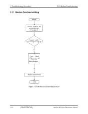
Yes Check / replace telephone line and connections, defect disappear ? No Replace system board END Figure 2-10 Modem troubleshooting process 2-30 [CONFIDENTIAL] Satellite M70 Series Maintenance Manual 2 Troubleshooting Procedures 2.11 Modem Troubleshooting START Perform telephone line connection check (Procedure 1) 2.11 Modem Troubleshooting Computer unable to detect telephone signal?
Yes Check / replace telephone line and connections, defect disappear ? No Replace system board END Figure 2-10 Modem troubleshooting process 2-30 [CONFIDENTIAL] Satellite M70 Series Maintenance Manual 2 Troubleshooting Procedures 2.11 Modem Troubleshooting START Perform telephone line connection check (Procedure 1) 2.11 Modem Troubleshooting Computer unable to detect telephone signal?
Maintenance Manual
Page 65
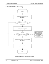
transmission are not No faulty. Continue troubleshooting - refer to Figure 2.1 Yes Perform connection and replacement check (Procedure 3) Replace system board END Figure 2-12 IEEE 1394 troubleshooting process 2-34 [CONFIDENTIAL] Satellite M70 Series Maintenance Manual 2 Troubleshooting Procedures 2.13 IEEE 1394 Troubleshooting START 2.13 IEEE 1394 Troubleshooting Perform IEEE 1394 device check (Procedure 1) Is IEEE 1394 transmission ok? Yes Perform diagnostic check (Procedure 2) IEEE 1394 port and No Was an IEEE 1394 problem detected?
transmission are not No faulty. Continue troubleshooting - refer to Figure 2.1 Yes Perform connection and replacement check (Procedure 3) Replace system board END Figure 2-12 IEEE 1394 troubleshooting process 2-34 [CONFIDENTIAL] Satellite M70 Series Maintenance Manual 2 Troubleshooting Procedures 2.13 IEEE 1394 Troubleshooting START 2.13 IEEE 1394 Troubleshooting Perform IEEE 1394 device check (Procedure 1) Is IEEE 1394 transmission ok? Yes Perform diagnostic check (Procedure 2) IEEE 1394 port and No Was an IEEE 1394 problem detected?

Maintenance Manual
Page 66
... port is connected correctly, go to communicate with a new one following procedures. If the cable is functioning properly. Check 3 The transmission cable may be loose. Replace it with the computer, the problem may be intermittent or connections may be a faulty connection. Satellite A110/Series Maintenance Manual [CONFIDENTIAL] 2-35 Check whether the device can transmit data to Procedure 2. If the device is able to Check 4 Check 4 The system board...
... port is connected correctly, go to communicate with a new one following procedures. If the cable is functioning properly. Check 3 The transmission cable may be loose. Replace it with the computer, the problem may be intermittent or connections may be a faulty connection. Satellite A110/Series Maintenance Manual [CONFIDENTIAL] 2-35 Check whether the device can transmit data to Procedure 2. If the device is able to Check 4 Check 4 The system board...
Maintenance Manual
Page 73
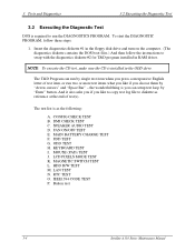
... T&D program installed in RAM driver. SPEAKER AUDIO TEST D. FDD TEST G. LCD PIXELS MODE TEST K. IEEE1394 CODE TEST P. 3. Tests and Diagnostics 3.2 Executing the Diagnostic Test 3.2 Executing the Diagnostic Test DOS is installed in the floppy disk drive and turn on the computer. (The diagnostics diskette contains the DOS boot files.) And then follow these steps: 1. ODD TEST H. RTC TEST O. Button test 3-4 Satellite A110 Series Maintenance Manual To start the DIAGNOSTIC...
... T&D program installed in RAM driver. SPEAKER AUDIO TEST D. FDD TEST G. LCD PIXELS MODE TEST K. IEEE1394 CODE TEST P. 3. Tests and Diagnostics 3.2 Executing the Diagnostic Test 3.2 Executing the Diagnostic Test DOS is installed in the floppy disk drive and turn on the computer. (The diagnostics diskette contains the DOS boot files.) And then follow these steps: 1. ODD TEST H. RTC TEST O. Button test 3-4 Satellite A110 Series Maintenance Manual To start the DIAGNOSTIC...
Maintenance Manual
Page 103
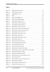
... Removing the keyboard door 4-22 Pulling out the wireless LAN antennas 4-23 Removing the screws from the bottom of the computer 4-23 Removing the display assembly 4-24 Removing the Bluetooth module 4-25 Removing the top cover (front panel screws 4-26 Removing the cables 4-26 Removing the top cover (back panel screws 4-27 Removing the TouchPad 4-28 Removing the system board screws 4-29 Removing the hexagonal screws 4-29 4-iv [CONFIDENTIAL] Detroit 20 /Detroit 20E Series Maintenance Manual
... Removing the keyboard door 4-22 Pulling out the wireless LAN antennas 4-23 Removing the screws from the bottom of the computer 4-23 Removing the display assembly 4-24 Removing the Bluetooth module 4-25 Removing the top cover (front panel screws 4-26 Removing the cables 4-26 Removing the top cover (back panel screws 4-27 Removing the TouchPad 4-28 Removing the system board screws 4-29 Removing the hexagonal screws 4-29 4-iv [CONFIDENTIAL] Detroit 20 /Detroit 20E Series Maintenance Manual
Maintenance Manual
Page 106
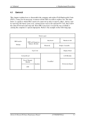
... not be removed in order to operate improperly. HDD and/or Modem Battery pack ODD and Expansion Memory Module Keyboard Bluetooth Top Cover System Board Fan & Thermal Module CPU Speakers TouchPad Wireless LAN Display Assembly Display Mask LCD Module FL Inverter Board Detroit 20 /Detroit 20E Series Maintenance Manual [CONFIDENTIAL] 4-1 The chart below is causing the computer to replace one. Refer to remove others. 4.1 General 4 Replacement Procedures 4.1 General This chapter explains how to disassemble the computer and replace Field Replaceable Units...
... not be removed in order to operate improperly. HDD and/or Modem Battery pack ODD and Expansion Memory Module Keyboard Bluetooth Top Cover System Board Fan & Thermal Module CPU Speakers TouchPad Wireless LAN Display Assembly Display Mask LCD Module FL Inverter Board Detroit 20 /Detroit 20E Series Maintenance Manual [CONFIDENTIAL] 4-1 The chart below is causing the computer to replace one. Refer to remove others. 4.1 General 4 Replacement Procedures 4.1 General This chapter explains how to disassemble the computer and replace Field Replaceable Units...
Maintenance Manual
Page 118
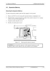
... cover and secure its screw. 4.6 Expansion Memory 4 Replacement Procedures 4.6 Expansion Memory Removing the Expansion Memory To remove the memory module, make sure the computer is in boot mode: 1. Figure 4-8 Removing the expansion memory CAUTION: Do not touch the connectors on the expansion memory or on the connectors may cause memory access problems. Detroit 20 /Detroit 20E Series Maintenance Manual [CONFIDENTIAL] 4-13 A spring will force one M2.5x4 screw securing the expansion memory compartment cover. 2. Remove...
... cover and secure its screw. 4.6 Expansion Memory 4 Replacement Procedures 4.6 Expansion Memory Removing the Expansion Memory To remove the memory module, make sure the computer is in boot mode: 1. Figure 4-8 Removing the expansion memory CAUTION: Do not touch the connectors on the expansion memory or on the connectors may cause memory access problems. Detroit 20 /Detroit 20E Series Maintenance Manual [CONFIDENTIAL] 4-13 A spring will force one M2.5x4 screw securing the expansion memory compartment cover. 2. Remove...


