Maintenance Manual
Page 3
.... The procedures described in this manual. WARNING: "Warning" indicates the existence of the wrong battery can cause the battery to explode. Preface This maintenance manual describes how to perform hardware service maintenance for the Toshiba Personal Computer Satellite A110/Satellite Pro A110, referred to as shown below. SAFETY PRECAUTIONS Four types of these messages will be sure...
.... The procedures described in this manual. WARNING: "Warning" indicates the existence of the wrong battery can cause the battery to explode. Preface This maintenance manual describes how to perform hardware service maintenance for the Toshiba Personal Computer Satellite A110/Satellite Pro A110, referred to as shown below. SAFETY PRECAUTIONS Four types of these messages will be sure...
Maintenance Manual
Page 7
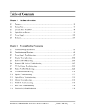
... Chapter 1 Hardware Overview 1.1 Features ...1-1 1.2 System Unit...1-6 1.3 2.5-inch Hard Disk Drive 1-8 1.4 Optical device Drives...1-9 1.5 Power Supply ...1-12 1.6 Batteries ...1-14 Chapter 2 Troubleshooting Procedures 2.1 Troubleshooting Introduction 2-1 2.2 Troubleshooting Flowchart 2-2 2.3 Power Supply Troubleshooting 2-7 2.4 Display Troubleshooting 2-12 2.5 Keyboard Troubleshooting 2-15...32 2.12 PCMCIA Troubleshooting 2-34 2.13 IEEE 1394 Troubleshooting 2-36 2.14 Wireless LAN Troubleshooting 2-38 Satellite A110/Satellite Pro A110 Series Maintenance Manual [CONFIDENTIAL] vii
... Chapter 1 Hardware Overview 1.1 Features ...1-1 1.2 System Unit...1-6 1.3 2.5-inch Hard Disk Drive 1-8 1.4 Optical device Drives...1-9 1.5 Power Supply ...1-12 1.6 Batteries ...1-14 Chapter 2 Troubleshooting Procedures 2.1 Troubleshooting Introduction 2-1 2.2 Troubleshooting Flowchart 2-2 2.3 Power Supply Troubleshooting 2-7 2.4 Display Troubleshooting 2-12 2.5 Keyboard Troubleshooting 2-15...32 2.12 PCMCIA Troubleshooting 2-34 2.13 IEEE 1394 Troubleshooting 2-36 2.14 Wireless LAN Troubleshooting 2-38 Satellite A110/Satellite Pro A110 Series Maintenance Manual [CONFIDENTIAL] vii
Maintenance Manual
Page 8
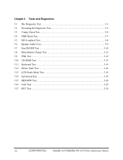
Chapter 3 Tests and Diagnostics 3.1 The Diagnostic Test ...3-1 3.2 Executing the Diagnostic Test 3-2 3.3 Config Check Test...3-6 3.4 DMI Check Test ...3-7 3.5 PIO Loopback Test...3-8 3.6 Speaker Audio Test ...3-9 3.7 Fan ON/OFF Test...3-10 3.8 Main Battery Charge Test 3-11 3.9 FDD Test ...3-12 3.10 CD-ROM Test ...3-13 3.11 Keyboard Test ...3-14 3.12 Mouse (Pad) Test ...3-16 3.13 LCD Pixels Mode Test 3-18 3.14 Lid Switch Test ...3-19 3.15 HDD R/W Test ...3-20 3.16 LAN Test...3-22 3.17 RTC Test ...3-24 viii [CONFIDENTIAL] Satellite A110/Satellite Pro A110 Series Maintenance Manual
Chapter 3 Tests and Diagnostics 3.1 The Diagnostic Test ...3-1 3.2 Executing the Diagnostic Test 3-2 3.3 Config Check Test...3-6 3.4 DMI Check Test ...3-7 3.5 PIO Loopback Test...3-8 3.6 Speaker Audio Test ...3-9 3.7 Fan ON/OFF Test...3-10 3.8 Main Battery Charge Test 3-11 3.9 FDD Test ...3-12 3.10 CD-ROM Test ...3-13 3.11 Keyboard Test ...3-14 3.12 Mouse (Pad) Test ...3-16 3.13 LCD Pixels Mode Test 3-18 3.14 Lid Switch Test ...3-19 3.15 HDD R/W Test ...3-20 3.16 LAN Test...3-22 3.17 RTC Test ...3-24 viii [CONFIDENTIAL] Satellite A110/Satellite Pro A110 Series Maintenance Manual
Maintenance Manual
Page 9
Chapter 4 Replacement Procedures 4.1 General...4-1 4.2 Battery...4-7 4.3 PC Card...4-8 4.4 HDD...4-10 4.5 Modem ...4-12 4.6 Expansion Memory...4-13 4.7 Wireless LAN Unit ...4-15 4.8 Optical Drive...4-18 4.9 Keyboard...4-20 4.10 Direct Assembly...4-22 4.11 Bluetooth...4-25 4.12 Top Cover ...4-26 4.13 Touch Pad ...4-28 4.14 System Board ...4-29 4.15 Speakers ...4-31 4.16 Thermal Module...4-32 4.17 CPU and Fan ...4-33 4.18 Display Mask ...4-35 4.19 LCD Module ...4-36 4.20 FL Inverter Board ...4-38 Satellite A110/Satellite Pro A110 Series Maintenance Manual [CONFIDENTIAL] ix
Chapter 4 Replacement Procedures 4.1 General...4-1 4.2 Battery...4-7 4.3 PC Card...4-8 4.4 HDD...4-10 4.5 Modem ...4-12 4.6 Expansion Memory...4-13 4.7 Wireless LAN Unit ...4-15 4.8 Optical Drive...4-18 4.9 Keyboard...4-20 4.10 Direct Assembly...4-22 4.11 Bluetooth...4-25 4.12 Top Cover ...4-26 4.13 Touch Pad ...4-28 4.14 System Board ...4-29 4.15 Speakers ...4-31 4.16 Thermal Module...4-32 4.17 CPU and Fan ...4-33 4.18 Display Mask ...4-35 4.19 LCD Module ...4-36 4.20 FL Inverter Board ...4-38 Satellite A110/Satellite Pro A110 Series Maintenance Manual [CONFIDENTIAL] ix

Maintenance Manual
Page 13
1 Hardware Overview Chapter 1 Contents 1.1 Features ...1-1 1.2 System Unit...1-6 1.3 2.5-inch Hard Disk Drive 1-8 1.4 Optical Device Drives 1-9 1.4.1 DVD-ROM & CD-RW 1-9 1.4.2 DVD Super Multi drive supporting ±R Double Layer 1-10 1.5 Power Supply ...1-11 1.6 Batteries ...1-13 1.6.1 Main Battery 1-14 1.6.2 RTC battery 1-15 Detroit 20 /Detroit 20E Series Maintenance Manual [CONFIDENTIAL] 1-iii
1 Hardware Overview Chapter 1 Contents 1.1 Features ...1-1 1.2 System Unit...1-6 1.3 2.5-inch Hard Disk Drive 1-8 1.4 Optical Device Drives 1-9 1.4.1 DVD-ROM & CD-RW 1-9 1.4.2 DVD Super Multi drive supporting ±R Double Layer 1-10 1.5 Power Supply ...1-11 1.6 Batteries ...1-13 1.6.1 Main Battery 1-14 1.6.2 RTC battery 1-15 Detroit 20 /Detroit 20E Series Maintenance Manual [CONFIDENTIAL] 1-iii
Maintenance Manual
Page 16
... Complete ACPI 1.0B function ‰ Power • 4-cell Lithium Ion smart battery pack with 14.4V*2000mAh • 6-cell Lithium Ion smart battery pack with 10.8V*4000mAh • 8-cell Lithium Ion smart battery pack with 14.4V*4300mAh • Approximately 12 hours or longer charging time to... with system switched off • Approximately 1.5 days discharging time in Standby Mode for the 8-cell battery, 1 day for the 6-cell battery, and 0.75 days for 4-cell battery • Discharge time in shutdown mode is approximately 1 month ‰ HDD • 9.5mm, 2.5" HDD up to 120 GB • Supports...
... Complete ACPI 1.0B function ‰ Power • 4-cell Lithium Ion smart battery pack with 14.4V*2000mAh • 6-cell Lithium Ion smart battery pack with 10.8V*4000mAh • 8-cell Lithium Ion smart battery pack with 14.4V*4300mAh • Approximately 12 hours or longer charging time to... with system switched off • Approximately 1.5 days discharging time in Standby Mode for the 8-cell battery, 1 day for the 6-cell battery, and 0.75 days for 4-cell battery • Discharge time in shutdown mode is approximately 1 month ‰ HDD • 9.5mm, 2.5" HDD up to 120 GB • Supports...
Maintenance Manual
Page 17
... & DVD-ROM drive • 12.7mm height DVD Super Multi drive supporting ±R Double Layer ‰ Optional devices • DVD-ROM module • Li-Ion Battery pack • AC adapter • HDD pack ‰ Keyboard The computer's keyboard has 101/102 keys and the layouts are five types of keys: typewriter...
... & DVD-ROM drive • 12.7mm height DVD Super Multi drive supporting ±R Double Layer ‰ Optional devices • DVD-ROM module • Li-Ion Battery pack • AC adapter • HDD pack ‰ Keyboard The computer's keyboard has 101/102 keys and the layouts are five types of keys: typewriter...
Maintenance Manual
Page 20
... 200M with RTL8100CL for 10M/100M LAN • Realtek ALC861 for HD CODEC ‰ Keyboard controller • ENE KB910 is use as keyboard controller and battery management unit. ‰ Memory • No on-board memory • Mobile Intel® 945GM Express Chipset with DDRII-533/667MHz • ATI Radeon® XPRESS...
... 200M with RTL8100CL for 10M/100M LAN • Realtek ALC861 for HD CODEC ‰ Keyboard controller • ENE KB910 is use as keyboard controller and battery management unit. ‰ Memory • No on-board memory • Mobile Intel® 945GM Express Chipset with DDRII-533/667MHz • ATI Radeon® XPRESS...

Maintenance Manual
Page 25
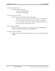
...register. ‰ Input port management • The EC monitors the following input signal status: - Battery and temperature ‰ AC adaptor and battery check • The EC checks the following by the low battery status. • The EC controls the following values: - AC adaptor connected ‰ Abnormal ...on or off, the EC starts the power on or off sequence. - Battery LED (two colors: orange and green) • Green solid = The battery is fully charged. • Orange = The computer is quick-charging the battery / The battery is low. ‰ Power ON/OFF sequence • When power is...
...register. ‰ Input port management • The EC monitors the following input signal status: - Battery and temperature ‰ AC adaptor and battery check • The EC checks the following by the low battery status. • The EC controls the following values: - AC adaptor connected ‰ Abnormal ...on or off, the EC starts the power on or off sequence. - Battery LED (two colors: orange and green) • Green solid = The battery is fully charged. • Orange = The computer is quick-charging the battery / The battery is low. ‰ Power ON/OFF sequence • When power is...
Maintenance Manual
Page 26
... by the gas gauge. - 1 Hardware Overview 1.5 Power Supply ‰ Battery charging control • The EC controls the following. - The detection of full charge ‰ Detection of the newly installed battery. ‰ Battery capacity calculation • The EC reads battery remaining and percentage capacity from the battery through SMBus. 1-12 [CONFIDENTIAL] Detroit 20 /Detroit 20E Series...
... by the gas gauge. - 1 Hardware Overview 1.5 Power Supply ‰ Battery charging control • The EC controls the following. - The detection of full charge ‰ Detection of the newly installed battery. ‰ Battery capacity calculation • The EC reads battery remaining and percentage capacity from the battery through SMBus. 1-12 [CONFIDENTIAL] Detroit 20 /Detroit 20E Series...

Maintenance Manual
Page 27
... the table below. Battery name Material Output voltage Capacity Main battery Lithium-Ion 14.4V(8cell) 4300mAH Main battery Lithium-Ion 10.8V(6cell) 4000mAH Main battery * Lithium-Ion 14.4V(4cell) 2000mAH RTC battery Lithium-Ion 3.0 V 15mAH * The available of battery: ‰ Main battery pack (18650 size) ‰ RTC battery The removable main battery pack is the computer...
... the table below. Battery name Material Output voltage Capacity Main battery Lithium-Ion 14.4V(8cell) 4300mAH Main battery Lithium-Ion 10.8V(6cell) 4000mAH Main battery * Lithium-Ion 14.4V(4cell) 2000mAH RTC battery Lithium-Ion 3.0 V 15mAH * The available of battery: ‰ Main battery pack (18650 size) ‰ RTC battery The removable main battery pack is the computer...

Maintenance Manual
Page 28
...affected by a power supply microprocessor that is mounted on or off and detects a full charge when the AC adaptor and battery are two types of quick charge: quick charge when the system is powered off and normal charge when the system is ...hours or longer NOTES 1. Overcharging could cause the battery to the computer. The battery or output voltage is charging. 1-14 [CONFIDENTIAL] Detroit 20 /Detroit 20E Series Maintenance Manual The battery temperature is removed. 3. 1 Hardware Overview 1.6 Batteries 1.6.1 Main Battery Battery charging is controlled by the amount of power the...
...affected by a power supply microprocessor that is mounted on or off and detects a full charge when the AC adaptor and battery are two types of quick charge: quick charge when the system is powered off and normal charge when the system is ...hours or longer NOTES 1. Overcharging could cause the battery to the computer. The battery or output voltage is charging. 1-14 [CONFIDENTIAL] Detroit 20 /Detroit 20E Series Maintenance Manual The battery temperature is removed. 3. 1 Hardware Overview 1.6 Batteries 1.6.1 Main Battery Battery charging is controlled by the amount of power the...

Maintenance Manual
Page 29
The table below lists the charging time and data preservation period of the RTC battery. 1.6 Batteries 1 Hardware Overview 1.6.2 RTC battery The RTC battery provides power to keep the current date, time and other setup information in memory while the computer is powered on ) Data preservation period (full charge) Time About 24 hours 1 month Detroit 20 /Detroit 20E Series Maintenance Manual [CONFIDENTIAL] 1-15 The RTC battery is charged by the adaptor or main battery, while the computer is turned off. Status Charging Time (power on .
The table below lists the charging time and data preservation period of the RTC battery. 1.6 Batteries 1 Hardware Overview 1.6.2 RTC battery The RTC battery provides power to keep the current date, time and other setup information in memory while the computer is powered on ) Data preservation period (full charge) Time About 24 hours 1 month Detroit 20 /Detroit 20E Series Maintenance Manual [CONFIDENTIAL] 1-15 The RTC battery is charged by the adaptor or main battery, while the computer is turned off. Status Charging Time (power on .
Maintenance Manual
Page 32
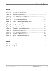
... Optical drive troubleshooting process 2-27 Modem troubleshooting process 2-30 PCMCIA troubleshooting process 2-32 IEEE 1394 troubleshooting process 2-34 Wireless LAN troubleshooting process 2-36 Tables Table 2-1 Battery LED ...2-8 Table 2-2 DC-IN LED...2-9 Satellite A110 /Satellite Pro A110 Series Maintenance Manual [CONFIDENTIAL] 2-iii
... Optical drive troubleshooting process 2-27 Modem troubleshooting process 2-30 PCMCIA troubleshooting process 2-32 IEEE 1394 troubleshooting process 2-34 Wireless LAN troubleshooting process 2-36 Tables Table 2-1 Battery LED ...2-8 Table 2-2 DC-IN LED...2-9 Satellite A110 /Satellite Pro A110 Series Maintenance Manual [CONFIDENTIAL] 2-iii
Maintenance Manual
Page 36
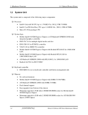
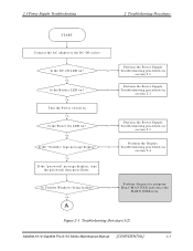
Y es A Perform diagnostics program . Figure 2-1 Troubleshooting flowchart (1/2) Satellite A110 /Satellite Pro A110 Series Maintenance Manual [CONFIDENTIAL] 2-3 Y es Perform the Pow er Supply No Troubleshooting procedures in section 2.3 Perform the Pow er Supply No ... 2 Troubleshooting Procedures START Connect the AC adapter to the D C-IN socket Is the DC-IN LED on ? Is Toshiba W indow s being loaded? No R un C M 165.EX E and select the H ARD D ISK item . Y es Is the Battery LED on? Perform the D isplay No Troubleshooting procedures in section 2.3 Is the...
Y es A Perform diagnostics program . Figure 2-1 Troubleshooting flowchart (1/2) Satellite A110 /Satellite Pro A110 Series Maintenance Manual [CONFIDENTIAL] 2-3 Y es Perform the Pow er Supply No Troubleshooting procedures in section 2.3 Perform the Pow er Supply No ... 2 Troubleshooting Procedures START Connect the AC adapter to the D C-IN socket Is the DC-IN LED on ? Is Toshiba W indow s being loaded? No R un C M 165.EX E and select the H ARD D ISK item . Y es Is the Battery LED on? Perform the D isplay No Troubleshooting procedures in section 2.3 Is the...
Maintenance Manual
Page 38
..., perform the Display Troubleshooting procedures in Section 2.8. 5. If an error is detected by the keyboard test, perform the Keyboard Troubleshooting procedures in Section 2.3. 2. Satellite A110 /Satellite Pro A110 Series Maintenance Manual [CONFIDENTIAL] 2-5 If an error is detected by the battery test, perform the Power Supply Troubleshooting procedures in Section 2.5. 4. The test program should be intermittent.
..., perform the Display Troubleshooting procedures in Section 2.8. 5. If an error is detected by the keyboard test, perform the Keyboard Troubleshooting procedures in Section 2.3. 2. Satellite A110 /Satellite Pro A110 Series Maintenance Manual [CONFIDENTIAL] 2-5 If an error is detected by the battery test, perform the Power Supply Troubleshooting procedures in Section 2.5. 4. The test program should be intermittent.
Maintenance Manual
Page 40
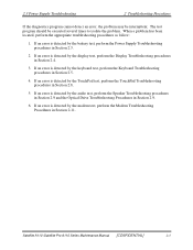
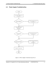
... the computer on? 2.3 Power Supply Troubleshooting 2.3 Power Supply Troubleshooting START Check Power Supply Status (Procedure 1) 2 Troubleshooting Procedures Are the DC-IN and Battery LEDs lit? Y es Replace system board Y es Run diagnostic program (Procedure 4) Perform internal connection No check (Procedure 5) END Figure 2-2 Power Supply Troubleshooting Process Satellite A110 /Satellite Pro A110 Series Maintenance Manual [CONFIDENTIAL] 2-7
... the computer on? 2.3 Power Supply Troubleshooting 2.3 Power Supply Troubleshooting START Check Power Supply Status (Procedure 1) 2 Troubleshooting Procedures Are the DC-IN and Battery LEDs lit? Y es Replace system board Y es Run diagnostic program (Procedure 4) Perform internal connection No check (Procedure 5) END Figure 2-2 Power Supply Troubleshooting Process Satellite A110 /Satellite Pro A110 Series Maintenance Manual [CONFIDENTIAL] 2-7
Maintenance Manual
Page 41
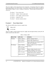
...Procedure 1 Power Status Check The following LEDS indicate the power supply status: Battery LED DC-IN LED The power supply controller displays the power supply status through the Battery and the DC-IN LEDS as instructed. The system is functioning properly,.... It's in the tables below. Amber color off Battery abnormal stop charging with the other Procedures as listed in discharging state 2-8 [CONFIDENTIAL] Satellite A110/Satellite Pro A110 Series Maintenance Manual Table 2-1 Battery LED Battery State Charging Discharging LED colors Definition Amber, solid on without...
...Procedure 1 Power Status Check The following LEDS indicate the power supply status: Battery LED DC-IN LED The power supply controller displays the power supply status through the Battery and the DC-IN LEDS as instructed. The system is functioning properly,.... It's in the tables below. Amber color off Battery abnormal stop charging with the other Procedures as listed in discharging state 2-8 [CONFIDENTIAL] Satellite A110/Satellite Pro A110 Series Maintenance Manual Table 2-1 Battery LED Battery State Charging Discharging LED colors Definition Amber, solid on without...

Maintenance Manual
Page 42
If the problem is not resolved, go to Procedure 2. To check the power supply status, install a battery pack and connect an AC adaptor to the DC-IN port on Off Table 2-2 DC-IN LED Power supply status AC power exists (LED... LED Solid on the computer and to Procedure 3. If the DC-IN LED or Battery LED is solid green). Check 1 Connect a new AC adaptor. Satellite A110 /Satellite Pro A110 Series Maintenance Manual [CONFIDENTIAL] 2-9 Check 2 Insert a new battery. No AC power exists. Procedure 2 Adaptor / battery replacement A faulty adaptor may not supply power or may not charge the...
If the problem is not resolved, go to Procedure 2. To check the power supply status, install a battery pack and connect an AC adaptor to the DC-IN port on Off Table 2-2 DC-IN LED Power supply status AC power exists (LED... LED Solid on the computer and to Procedure 3. If the DC-IN LED or Battery LED is solid green). Check 1 Connect a new AC adaptor. Satellite A110 /Satellite Pro A110 Series Maintenance Manual [CONFIDENTIAL] 2-9 Check 2 Insert a new battery. No AC power exists. Procedure 2 Adaptor / battery replacement A faulty adaptor may not supply power or may not charge the...

Maintenance Manual
Page 43
... close to 19 V, go to Check 3. If there is no damage, go to Procedure 4. 2-10 [CONFIDENTIAL] Satellite A110/Satellite Pro A110 Series Maintenance Manual If the battery is properly installed and the battery LED still does not light, go to Check 2. Check the power cable for breaks. Check 2 Make sure the... Flowchart Procedure 3 Power supply connection check The power supply wiring diagram is shown below: AC power cord AC adaptor AC adaptor cord System board Battery Any of the computer. • If the DC-IN input socket is loose, go to Procedure 5. • If it is not loose...
... close to 19 V, go to Check 3. If there is no damage, go to Procedure 4. 2-10 [CONFIDENTIAL] Satellite A110/Satellite Pro A110 Series Maintenance Manual If the battery is properly installed and the battery LED still does not light, go to Check 2. Check the power cable for breaks. Check 2 Make sure the... Flowchart Procedure 3 Power supply connection check The power supply wiring diagram is shown below: AC power cord AC adaptor AC adaptor cord System board Battery Any of the computer. • If the DC-IN input socket is loose, go to Procedure 5. • If it is not loose...


