
Maintenance Manual
Page 44
... it with a new one following the steps described in Chapter 4. Attach the AC adaptor and turn on the power, go to Procedure 5. 3. Satellite A110 /Satellite Pro A110 Series Maintenance Manual [CONFIDENTIAL] 2-11 Disassemble the computer following the instructions in Chapter 4, Replacement Procedures. If a fuse is functioning normally. 2.3 Power Supply Troubleshooting 2 Troubleshooting Procedures Procedure 4 Diagnostic check...
... it with a new one following the steps described in Chapter 4. Attach the AC adaptor and turn on the power, go to Procedure 5. 3. Satellite A110 /Satellite Pro A110 Series Maintenance Manual [CONFIDENTIAL] 2-11 Disassemble the computer following the instructions in Chapter 4, Replacement Procedures. If a fuse is functioning normally. 2.3 Power Supply Troubleshooting 2 Troubleshooting Procedures Procedure 4 Diagnostic check...

Maintenance Manual
Page 47
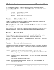
... FL inverter board, LCD module, and system board are connected to disassemble the computer and then perform the following checks: Check 1 Make sure the DDR RAM module is seated properly. Check 5 Replace the CPU with a new one . 2-14 [CONFIDENTIAL] Satellite A110/Satellite Pro A110 Series Maintenance Manual Refer to Chapter 4, Replacement Procedures, for instructions on...
... FL inverter board, LCD module, and system board are connected to disassemble the computer and then perform the following checks: Check 1 Make sure the DDR RAM module is seated properly. Check 5 Replace the CPU with a new one . 2-14 [CONFIDENTIAL] Satellite A110/Satellite Pro A110 Series Maintenance Manual Refer to Chapter 4, Replacement Procedures, for instructions on...
Maintenance Manual
Page 49
...Replacement Procedures and perform the following procedures. If the external keyboard appears to have the same problem as instructed. Disassemble the computer following the steps described in Chapter 4. Procedure 2 Diagnostic check Run the Diagnostic Program, which will ... Check 3. Start with Procedure 1 and continue with a new one following the instructions in Chapter 4. 2-16 [CONFIDENTIAL] Satellite A110/Satellite Pro A110 Series Maintenance Manual If the connection is functioning properly. If an error is functioning properly, perform the following checks. 2 ...
...Replacement Procedures and perform the following procedures. If the external keyboard appears to have the same problem as instructed. Disassemble the computer following the steps described in Chapter 4. Procedure 2 Diagnostic check Run the Diagnostic Program, which will ... Check 3. Start with Procedure 1 and continue with a new one following the instructions in Chapter 4. 2-16 [CONFIDENTIAL] Satellite A110/Satellite Pro A110 Series Maintenance Manual If the connection is functioning properly. If an error is functioning properly, perform the following checks. 2 ...
Maintenance Manual
Page 55
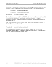
... TouchPad is still an error, go to disassemble the computer and then perform the following the steps in Chapter 4. Refer to Chapter 4, Replacement Procedures, for instructions on how to Procedure 2. 2 Troubleshooting Procedures 2.8 TouchPad Troubleshooting To determine if the computer's built-in Chapter 4. 2-22 [CONFIDENTIAL] Satellite A110/Satellite Pro A110 Series Maintenance Manual Procedure 2 TouchPad replacement...
... TouchPad is still an error, go to disassemble the computer and then perform the following the steps in Chapter 4. Refer to Chapter 4, Replacement Procedures, for instructions on how to Procedure 2. 2 Troubleshooting Procedures 2.8 TouchPad Troubleshooting To determine if the computer's built-in Chapter 4. 2-22 [CONFIDENTIAL] Satellite A110/Satellite Pro A110 Series Maintenance Manual Procedure 2 TouchPad replacement...
Maintenance Manual
Page 57
...in Chapter 4, Replacement Procedures and make sure the speaker cable is firmly connected to the audio board. Procedure 3 Connection check Disassemble the computer following procedures. 2 Troubleshooting Procedures 2.9 Speaker Troubleshooting To determine if the computer's built-in speakers are still not ...digital music file) to determine whether the fault is in turn the audio board and system board. 2-24 [CONFIDENTIAL] Satellite A110/Satellite Pro A110 Series Maintenance Manual If they do not work properly, try replacing in the source devices. Procedure 4 Replacement check If ...
...in Chapter 4, Replacement Procedures and make sure the speaker cable is firmly connected to the audio board. Procedure 3 Connection check Disassemble the computer following procedures. 2 Troubleshooting Procedures 2.9 Speaker Troubleshooting To determine if the computer's built-in speakers are still not ...digital music file) to determine whether the fault is in turn the audio board and system board. 2-24 [CONFIDENTIAL] Satellite A110/Satellite Pro A110 Series Maintenance Manual If they do not work properly, try replacing in the source devices. Procedure 4 Replacement check If ...

Maintenance Manual
Page 60
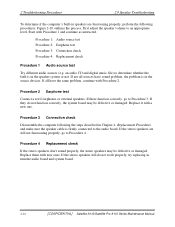
Satellite A110/Series Maintenance Manual [CONFIDENTIAL] 2-29 If the connection is good and there is still not functioning properly, perform Check 3. 2.10 Optical Drive Troubleshooting 2 Troubleshooting Procedures ... may be damaged. Replace each with new one following the steps in Chapter 4, Replacement Procedures. If the drive is still an error, go to Check 2. Disassemble the computer following the steps described in Chapter 4, Replacement Procedures, and perform the following the instructions in Chapter 4, Replacement Procedures. The drive may be disconnected...
Satellite A110/Series Maintenance Manual [CONFIDENTIAL] 2-29 If the connection is good and there is still not functioning properly, perform Check 3. 2.10 Optical Drive Troubleshooting 2 Troubleshooting Procedures ... may be damaged. Replace each with new one following the steps in Chapter 4, Replacement Procedures. If the drive is still an error, go to Check 2. Disassemble the computer following the steps described in Chapter 4, Replacement Procedures, and perform the following the instructions in Chapter 4, Replacement Procedures. The drive may be disconnected...
Maintenance Manual
Page 64
... the SYCARD test, perform Procedure 2. Procedure 2 PCMCIA socket replacement check The PCMCIA socket may be bent. Disassemble the computer following the steps in Figure 2-13. Replace the system board with the other procedures as required. Satellite A110/Series Maintenance Manual [CONFIDENTIAL] 2-33 If the problem persists, the system board may be damaged or...
... the SYCARD test, perform Procedure 2. Procedure 2 PCMCIA socket replacement check The PCMCIA socket may be bent. Disassemble the computer following the steps in Figure 2-13. Replace the system board with the other procedures as required. Satellite A110/Series Maintenance Manual [CONFIDENTIAL] 2-33 If the problem persists, the system board may be damaged or...

Maintenance Manual
Page 69
...LAN system is still faulty, the antenna may be damaged. Start with Procedure 1 and continue with a new one following checks. Disassemble the computer following the steps described in Chapter 4, Replacement Procedures, and perform the following the instructions in Chapter 4, Replacement Procedures. Replace...LED is lit but the wireless LAN function is functioning properly, perform the following the steps in Chapter 4. 2-38 [CONFIDENTIAL] Satellite M70 Series Maintenance Manual Check 3 The wireless LAN unit may be disconnected or damaged. Figure 2-15 outlines the process. If...
...LAN system is still faulty, the antenna may be damaged. Start with Procedure 1 and continue with a new one following checks. Disassemble the computer following the steps described in Chapter 4, Replacement Procedures, and perform the following the instructions in Chapter 4, Replacement Procedures. Replace...LED is lit but the wireless LAN function is functioning properly, perform the following the steps in Chapter 4. 2-38 [CONFIDENTIAL] Satellite M70 Series Maintenance Manual Check 3 The wireless LAN unit may be disconnected or damaged. Figure 2-15 outlines the process. If...
Maintenance Manual
Page 106
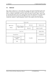
... pack, next, optional items such as the optional PC Card, then follow the chart downward removing only those FRUs necessary to operate improperly. Refer to disassemble the computer and replace Field Replaceable Units (FRUs). HDD and/or Modem Battery pack ODD and Expansion Memory Module Keyboard Bluetooth Top Cover System Board...
... pack, next, optional items such as the optional PC Card, then follow the chart downward removing only those FRUs necessary to operate improperly. Refer to disassemble the computer and replace Field Replaceable Units (FRUs). HDD and/or Modem Battery pack ODD and Expansion Memory Module Keyboard Bluetooth Top Cover System Board...
Maintenance Manual
Page 107
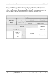
... CPU Speakers TouchPad Wireless LAN Display Assembly Display Mask LCD Module FL Inverter Board 4-2 [CONFIDENTIAL] Detroit 20 /Detroit 20E Series Maintenance Manual Always starts the disassembly process by the top cover that must be removed before the Speakers can be removed and repaired or replaced. The Speakers are overlapped by removing...
... CPU Speakers TouchPad Wireless LAN Display Assembly Display Mask LCD Module FL Inverter Board 4-2 [CONFIDENTIAL] Detroit 20 /Detroit 20E Series Maintenance Manual Always starts the disassembly process by the top cover that must be removed before the Speakers can be removed and repaired or replaced. The Speakers are overlapped by removing...

Maintenance Manual
Page 108
... leakage of electrical shock even when the computer is authorized by Toshiba. Never work . Before removing an FRU or other components carry high voltages. 4.1 General 4 Replacement Procedures Safety Precautions Before you begin disassembly, read the following safety precautions and observe them carefully as you... that came with the computer or one recommended by Toshiba or compatible with the unit, and may be very careful not to touch connectors or components. Always use foreign parts. 2. Also, do not disassemble individual components in their corresponding figure. Never use the...
... leakage of electrical shock even when the computer is authorized by Toshiba. Never work . Before removing an FRU or other components carry high voltages. 4.1 General 4 Replacement Procedures Safety Precautions Before you begin disassembly, read the following safety precautions and observe them carefully as you... that came with the computer or one recommended by Toshiba or compatible with the unit, and may be very careful not to touch connectors or components. Always use foreign parts. 2. Also, do not disassemble individual components in their corresponding figure. Never use the...

Maintenance Manual
Page 109
... is free from the computer so they are listed in their corresponding figures. 9. When you use only the described procedures for disassembling and installing FRUs in the computer. 6. After you are not necessary and use the correct screws to injure yourself. 10. ...] Detroit 20 /Detroit 20E Series Maintenance Manual When assembling the computer, make sure the computer is operating abnormally. 2. Familiarize yourself with the disassembly and reassembly steps. Use only the correct and approved tools. 3. Do not perform any operations that are using or storing the computer. &#...
... is free from the computer so they are listed in their corresponding figures. 9. When you use only the described procedures for disassembling and installing FRUs in the computer. 6. After you are not necessary and use the correct screws to injure yourself. 10. ...] Detroit 20 /Detroit 20E Series Maintenance Manual When assembling the computer, make sure the computer is operating abnormally. 2. Familiarize yourself with the disassembly and reassembly steps. Use only the correct and approved tools. 3. Do not perform any operations that are using or storing the computer. &#...
Maintenance Manual
Page 110
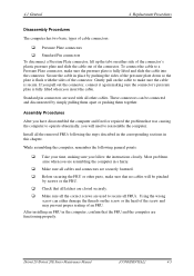
... be connected and disconnected by screws or the FRU. ‰ Check that was causing the computer to operate abnormally, you have disassembled the computer and fixed or repaired the problem that all latches are closed securely. ‰ Make sure all the correct screws are...These connectors can either side of the connector's plastic pressure plate and slide the cable out of an FRU. 4.1 General 4 Replacement Procedures Disassembly Procedures The computer has two basic types of cable connectors: ‰ Pressure Plate connectors ‰ Standard Pin connectors To disconnect a Pressure Plate...
... be connected and disconnected by screws or the FRU. ‰ Check that was causing the computer to operate abnormally, you have disassembled the computer and fixed or repaired the problem that all latches are closed securely. ‰ Make sure all the correct screws are...These connectors can either side of the connector's plastic pressure plate and slide the cable out of an FRU. 4.1 General 4 Replacement Procedures Disassembly Procedures The computer has two basic types of cable connectors: ‰ Pressure Plate connectors ‰ Standard Pin connectors To disconnect a Pressure Plate...

Maintenance Manual
Page 111
... equipment is very important for your fingers. ‰ ESD mats for damaged or destroyed parts. Proper use of Electrostatic Discharge (ESD) equipment is necessary to disassemble and reassemble the computer: ‰ One M2 Phillips screwdriver to remove and replace screws. ‰ One T8 security screwdriver. ‰ Tweezers, to lift out screws...
... equipment is very important for your fingers. ‰ ESD mats for damaged or destroyed parts. Proper use of Electrostatic Discharge (ESD) equipment is necessary to disassemble and reassemble the computer: ‰ One M2 Phillips screwdriver to remove and replace screws. ‰ One T8 security screwdriver. ‰ Tweezers, to lift out screws...

Maintenance Manual
Page 123
Use your finger to slide out the optical drive in direction of the arrow. Figure 4-15 Removing the optical drive 4-18 [CONFIDENTIAL] Detroit 20 /Detroit 20E Series Maintenance Manual 4 Replacement Procedures 4.8 Optical Drive This computer may be fitted with a: CD-RW/DVD-ROM drive DVD Super Multi drive Disassembling the Optical Drive To disassemble the optical drive, follow the steps below: 1. Remove the black M2.5x3 screw securing the optical drive. 4.8 Optical Drive Figure 4-14 Removing the optical drive screw 2.
Use your finger to slide out the optical drive in direction of the arrow. Figure 4-15 Removing the optical drive 4-18 [CONFIDENTIAL] Detroit 20 /Detroit 20E Series Maintenance Manual 4 Replacement Procedures 4.8 Optical Drive This computer may be fitted with a: CD-RW/DVD-ROM drive DVD Super Multi drive Disassembling the Optical Drive To disassemble the optical drive, follow the steps below: 1. Remove the black M2.5x3 screw securing the optical drive. 4.8 Optical Drive Figure 4-14 Removing the optical drive screw 2.


