
User Guide
Page 175
...," or "Always Low." ❖ General - 175 Toshiba Utilities TOSHIBA Console Select the boot device by pressing the right or left arrow keys, then pressing the Enter key. Since the system is a quick-booting system, you must press the arrow keys immediately after pressing the power button. ❖ Keyboard-... set the "CPU Frequency Mode" to view the current BIOS. ❖ Device Config-Shows the Device configuration options. This function does not work with a USB keyboard. ❖ USB-Allows you to configure the Fn function key emulation for the built-in LCD display and external video...
...," or "Always Low." ❖ General - 175 Toshiba Utilities TOSHIBA Console Select the boot device by pressing the right or left arrow keys, then pressing the Enter key. Since the system is a quick-booting system, you must press the arrow keys immediately after pressing the power button. ❖ Keyboard-... set the "CPU Frequency Mode" to view the current BIOS. ❖ Device Config-Shows the Device configuration options. This function does not work with a USB keyboard. ❖ USB-Allows you to configure the Fn function key emulation for the built-in LCD display and external video...
Maintenance Manual
Page 4
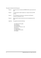
... following : q Handling the LCD module q Board layout q Pin assignments q Keyboard scan/character codes q Key layout q Wiring diagrams q BIOS Rewrite Procedures q Reliability iv PORTEGE M100 Maintenance Manual (960 -452) Appendices The appendices describe the following parts: Chapter 1 Hardware Overview describes the PORTEGE M100 system unit and each FRU. Chapter 2 Troubleshooting Procedures explains how to diagnose and resolve...
... following : q Handling the LCD module q Board layout q Pin assignments q Keyboard scan/character codes q Key layout q Wiring diagrams q BIOS Rewrite Procedures q Reliability iv PORTEGE M100 Maintenance Manual (960 -452) Appendices The appendices describe the following parts: Chapter 1 Hardware Overview describes the PORTEGE M100 system unit and each FRU. Chapter 2 Troubleshooting Procedures explains how to diagnose and resolve...

Maintenance Manual
Page 10
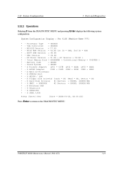
Appendices Appendix A Appendix B Appendix C Appendix D Appendix E Appendix F Appendix G Appendix H Appendix I Handling the LCD Module A-1 Board Layout B-1 Pin Assignments C-1 Keyboard Scan/Character Codes D-1 Key Layout ...E-1 Wiring Diagrams F-1 BIOS Rewrite Procedures G-1 EC/KBC Rewrite Procedures H-1 Reliability...I-1 x PORTEGE M100 Maintenance Manual (960 -452)
Appendices Appendix A Appendix B Appendix C Appendix D Appendix E Appendix F Appendix G Appendix H Appendix I Handling the LCD Module A-1 Board Layout B-1 Pin Assignments C-1 Keyboard Scan/Character Codes D-1 Key Layout ...E-1 Wiring Diagrams F-1 BIOS Rewrite Procedures G-1 EC/KBC Rewrite Procedures H-1 Reliability...I-1 x PORTEGE M100 Maintenance Manual (960 -452)

Maintenance Manual
Page 60
q If an error message is shown on the system board and initializes it. Then press [F1] key (b)*** Bad check sum (ROM) *** Check system. Then press [F1] key 2-18 PORTEGE M100 Maintenance Manual (960-452) q If an operating system is properly loaded, go to Procedure 2. If any error message is inconsistent...Bad time function *** Check system. These errors occur, when the system configuration preserved in the BIOS ROM. The IRT tests each IC on the display, perform Check 1. If you press the F1 key as the actual configuration or when the data is lost. q If nothing is displayed, go...
q If an error message is shown on the system board and initializes it. Then press [F1] key (b)*** Bad check sum (ROM) *** Check system. Then press [F1] key 2-18 PORTEGE M100 Maintenance Manual (960-452) q If an operating system is properly loaded, go to Procedure 2. If any error message is inconsistent...Bad time function *** Check system. These errors occur, when the system configuration preserved in the BIOS ROM. The IRT tests each IC on the display, perform Check 1. If you press the F1 key as the actual configuration or when the data is lost. q If nothing is displayed, go...

Maintenance Manual
Page 65
...check and initialization 03h Resume branch 04h SMRAM initialization 05h Storage of CPU state map 06h Advance processing before initializing PCI bus Message Key input check Check sum error check Signature error check IRT Check system Protecting cache Special register, Intel chip set initialization PIT ch... BIOS RAM area checksum System BIOS ROM to RAM copy SMRAM initialization Wake Up check SMRAM base rewrite and BIOS CPU state map store Set SMI handler to runtime Rewriting of SRAM base Storage of CPU s tate map Setting of device necessary before initializing of PCI bus PORTEGE M100 ...
...check and initialization 03h Resume branch 04h SMRAM initialization 05h Storage of CPU state map 06h Advance processing before initializing PCI bus Message Key input check Check sum error check Signature error check IRT Check system Protecting cache Special register, Intel chip set initialization PIT ch... BIOS RAM area checksum System BIOS ROM to RAM copy SMRAM initialization Wake Up check SMRAM base rewrite and BIOS CPU state map store Set SMI handler to runtime Rewriting of SRAM base Storage of CPU s tate map Setting of device necessary before initializing of PCI bus PORTEGE M100 ...

Maintenance Manual
Page 116
... rotation of the BIOS ROM (range: F0000h to FFFFFh, 64KB) on the System Board. When you want to the SYSTEM test menu, press Enter. The following message will appear. Subtest 01 ROM Checksum This subtest executes a checksum test of the fan stops and press Enter. *** Fan ON *** : Press [Enter] key? PORTEGE M100 Maintenance Manual... MENU, press Enter and follow the directions on /off command. Make sure the rotation of the fan starts and press Enter. *** Fan OFF *** : Press [Enter] key? Subtest 06 Quick Charge This subtest checks the status for the quick charge.
... rotation of the BIOS ROM (range: F0000h to FFFFFh, 64KB) on the System Board. When you want to the SYSTEM test menu, press Enter. The following message will appear. Subtest 01 ROM Checksum This subtest executes a checksum test of the fan stops and press Enter. *** Fan ON *** : Press [Enter] key? PORTEGE M100 Maintenance Manual... MENU, press Enter and follow the directions on /off command. Make sure the rotation of the fan starts and press Enter. *** Fan OFF *** : Press [Enter] key? Subtest 06 Quick Charge This subtest checks the status for the quick charge.

Maintenance Manual
Page 118
...the temperature of the outside and temperature of the inside. Battery Data * Battery Type = XXXXXXXXXXXX PORTEGE M100 Maintenance Manual (960-452) 3-11 The following message appears. * Get! 3.4 System Test ...10 Subtest 11 Subtest 12 Subtest 13 Temperature surveillance test Settings at the start of test • BIOS test mode (FAN -forced high speed, prohibition of SM interruptionetc.) • Prohibition of TCC ...system department. Blue-tooth Switch "ON", and press [Enter] key Blue-tooth Switch "OFF", and press [Enter] key Battery F/W test This subtest reads F/W data from the battery and...
...the temperature of the outside and temperature of the inside. Battery Data * Battery Type = XXXXXXXXXXXX PORTEGE M100 Maintenance Manual (960-452) 3-11 The following message appears. * Get! 3.4 System Test ...10 Subtest 11 Subtest 12 Subtest 13 Temperature surveillance test Settings at the start of test • BIOS test mode (FAN -forced high speed, prohibition of SM interruptionetc.) • Prohibition of TCC ...system department. Blue-tooth Switch "ON", and press [Enter] key Blue-tooth Switch "OFF", and press [Enter] key Battery F/W test This subtest reads F/W data from the battery and...
Maintenance Manual
Page 158
...- X Hard Disk Drive(s) #1 Sectors = XXXXX, (XXXXX MB) * - PORTEGE M100 Maintenance Manual (960-452) 3-49 MS-DOS Version = V7.XX * - PS Micon Version = V1.XX ( EC Version = VX.XX ) * - Sound System = XXXXX * - X HWSC = XXXXXXX #2 Sectors = XXXXX, (XXXXX MB) * - X Wireless LAN * - BIOS ROM Version = VX.XX 1st ID = XXH, 2nd ID = XXH...- X Printer Adapter LPT1 = 0378 LPT2 = XXXX LPT3 = XXXX * - X ASYNC Adapter COM1 = 03F8 COM2 = XXXX COM3 = XXXX * - X Bluetooth * - X USB2.0 FIR Press [Enter] Key [Date = XXXX-YY-ZZ, XX:YY:ZZ] Press Enter to return to the DIAGNOSTIC MENU.
...- X Hard Disk Drive(s) #1 Sectors = XXXXX, (XXXXX MB) * - PORTEGE M100 Maintenance Manual (960-452) 3-49 MS-DOS Version = V7.XX * - PS Micon Version = V1.XX ( EC Version = VX.XX ) * - Sound System = XXXXX * - X HWSC = XXXXXXX #2 Sectors = XXXXX, (XXXXX MB) * - X Wireless LAN * - BIOS ROM Version = VX.XX 1st ID = XXH, 2nd ID = XXH...- X Printer Adapter LPT1 = 0378 LPT2 = XXXX LPT3 = XXXX * - X ASYNC Adapter COM1 = 03F8 COM2 = XXXX COM3 = XXXX * - X Bluetooth * - X USB2.0 FIR Press [Enter] Key [Date = XXXX-YY-ZZ, XX:YY:ZZ] Press Enter to return to the DIAGNOSTIC MENU.
Maintenance Manual
Page 316
... External Microphone connector (5pin C-29 C.31 PJ6002 Headphone connector (5pin C-29 C.32 PJ3290 BT Switch Board I/F connector (2pin C-30 Appendix D Keyboard Scan/Character Codes D-1 Appendix E Key Layout...E-1 Appendix F Wiring Diagrams F-1 Appendix G BIOS Rewrite Procedures G-1 Appendix H EC/KBC Rewrite Procedures H-1 Appendix I Reliability...I-1 App-iv PORTEGE M100 Maintenance Manual (960 -452)
... External Microphone connector (5pin C-29 C.31 PJ6002 Headphone connector (5pin C-29 C.32 PJ3290 BT Switch Board I/F connector (2pin C-30 Appendix D Keyboard Scan/Character Codes D-1 Appendix E Key Layout...E-1 Appendix F Wiring Diagrams F-1 Appendix G BIOS Rewrite Procedures G-1 Appendix H EC/KBC Rewrite Procedures H-1 Appendix I Reliability...I-1 App-iv PORTEGE M100 Maintenance Manual (960 -452)

Maintenance Manual
Page 381
PORTEGE M100 Maintenance Manual (960-452) G-1 Appendix G BIOS Rewrite Procedures Appendices Appendix G Appendix G BIOS Rewrite Procedures This Appendix explains how to rewrite the system BIOS program when you need the following key. Turn on the screen.) The BIOS rewriting starts. 6. Set the system to the computer. 3. Remove the external cable and PC card. 4. Rewriting the BIOS 1. For example (US...
PORTEGE M100 Maintenance Manual (960-452) G-1 Appendix G BIOS Rewrite Procedures Appendices Appendix G Appendix G BIOS Rewrite Procedures This Appendix explains how to rewrite the system BIOS program when you need the following key. Turn on the screen.) The BIOS rewriting starts. 6. Set the system to the computer. 3. Remove the external cable and PC card. 4. Rewriting the BIOS 1. For example (US...

Maintenance Manual
Page 383
...you update the EC/KBC system. Allow sufficient time. The computer is not hung up the computer. 4. PORTEGE M100 Maintenance Manual (960-452) H-1 Appendix H EC/KBC Rewrite Procedures Appendices Appendix H Appendix H EC/KBC Rewrite... the EC/KBS only when instructed by a diagnostic disk release notice. 2. In this case, insert the BIOS/EC/KBC rewriting disk, and the EC/KBC will be impossible to boot mode. 2. Normally it might... . Turn on the power while holding down the Tab key. (Keep holding down the key until a message appears on the conditions of the EC/KBC has been erased.
...you update the EC/KBC system. Allow sufficient time. The computer is not hung up the computer. 4. PORTEGE M100 Maintenance Manual (960-452) H-1 Appendix H EC/KBC Rewrite Procedures Appendices Appendix H Appendix H EC/KBC Rewrite... the EC/KBS only when instructed by a diagnostic disk release notice. 2. In this case, insert the BIOS/EC/KBC rewriting disk, and the EC/KBC will be impossible to boot mode. 2. Normally it might... . Turn on the power while holding down the Tab key. (Keep holding down the key until a message appears on the conditions of the EC/KBC has been erased.

User Manual
Page 87
...application prior to enabling and configuring the FingerPrint Single Sign-On Feature. TOSHIBA is required to replace the User/BIOS Password (and, if applicable, the HDD (Hard Disk Drive) Password)...to Enable FingerPrint Single Sign-On Feature It is recommended that the keyboard cursor keys (movement) and enter key (selection) or the directional pad be accurately screen out unauthorized users at all... FingerPrint Single Sign On Feature. Satellite M100 4-9 It is enrolled before configuring the settings (please refer to register the User/BIOS Password and Windows Logon password before using...
...application prior to enabling and configuring the FingerPrint Single Sign-On Feature. TOSHIBA is required to replace the User/BIOS Password (and, if applicable, the HDD (Hard Disk Drive) Password)...to Enable FingerPrint Single Sign-On Feature It is recommended that the keyboard cursor keys (movement) and enter key (selection) or the directional pad be accurately screen out unauthorized users at all... FingerPrint Single Sign On Feature. Satellite M100 4-9 It is enrolled before configuring the settings (please refer to register the User/BIOS Password and Windows Logon password before using...
User Manual
Page 176
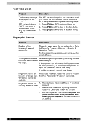
...another enrolled finger. On feature cannot be read , please logon by using TOSHIBA Password Utility and restart the system. 3. Fingerprint Power on the Protector Suite QL setting. 9-18 Satellite M100 Set the User Password by using another be enabled. The RTC battery ...]. 3. Press [F1] key. The fingerprint cannot Try the recognition process again using the correct posture. Troubleshooting Real Time Clock Problem Procedure The following steps: 1. Refer to register Security or Single Sign the User Password if it was not successful. BIOS setup will boot up. ...
...another enrolled finger. On feature cannot be read , please logon by using TOSHIBA Password Utility and restart the system. 3. Fingerprint Power on the Protector Suite QL setting. 9-18 Satellite M100 Set the User Password by using another be enabled. The RTC battery ...]. 3. Press [F1] key. The fingerprint cannot Try the recognition process again using the correct posture. Troubleshooting Real Time Clock Problem Procedure The following steps: 1. Refer to register Security or Single Sign the User Password if it was not successful. BIOS setup will boot up. ...


