Service Manual
Page 1
When repairing this manual and lead-free solder (*2). TOSHIBA CORPORATION 2008 Published in this green product, use the part(s) described in Japan, Jan. 2008 GREEN For (*1) and (*2), see the next page. This Service Manual describes replacement parts for the green product. SERVICE MANUAL FILE NO. 810-200803GR DVD Video Recorder /Video Cassette Recorder D-VR610KU The above model is classified as a green product (*1), as indicated by the underlined serial number.
When repairing this manual and lead-free solder (*2). TOSHIBA CORPORATION 2008 Published in this green product, use the part(s) described in Japan, Jan. 2008 GREEN For (*1) and (*2), see the next page. This Service Manual describes replacement parts for the green product. SERVICE MANUAL FILE NO. 810-200803GR DVD Video Recorder /Video Cassette Recorder D-VR610KU The above model is classified as a green product (*1), as indicated by the underlined serial number.
Service Manual
Page 3
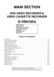
...Notes for Servicing 1-4-1 Preparation for Servicing 1-5-1 Cabinet Disassembly Instructions 1-6-1 Electrical Adjustment Instructions 1-7-1 How to Initialize the DVD Recorder & VCR 1-8-1 Firmware Renewal Mode 1-9-1 Troubleshooting 1-10-1 Function Indicator Symbols 1-11-1 Block Diagrams 1-12-1 Schematic Diagrams / BOARD's and ...Test Points 1-13-1 Waveforms 1-14-1 Wiring Diagram < VCR Section 1-15-1 Wiring Diagram < DVD Section 1-15-2 IC Pin Function Descriptions 1-16-1 Lead Identifications 1-17-1 Exploded Views...
...Notes for Servicing 1-4-1 Preparation for Servicing 1-5-1 Cabinet Disassembly Instructions 1-6-1 Electrical Adjustment Instructions 1-7-1 How to Initialize the DVD Recorder & VCR 1-8-1 Firmware Renewal Mode 1-9-1 Troubleshooting 1-10-1 Function Indicator Symbols 1-11-1 Block Diagrams 1-12-1 Schematic Diagrams / BOARD's and ...Test Points 1-13-1 Waveforms 1-14-1 Wiring Diagram < VCR Section 1-15-1 Wiring Diagram < DVD Section 1-15-2 IC Pin Function Descriptions 1-16-1 Lead Identifications 1-17-1 Exploded Views...
Service Manual
Page 4
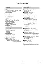
...TV format NTSC TV standard Recording Recording format VR (video recording) format Video format +VR format Recording discs DVD-Rewritable/-Recordable, DVD+Rewritable/+Recordable Video recording format Sampling frequency: 13.5 MHz Compression format: MPEG Audio recording format Sampling frequency: 48 kHz...level: 1 Vp-p (75Ω) C (color) - SPECIFICATIONS General System DVD-RW/-R, DVD+RW/+R, DVD-video, CD-DA, CD-RW/-R, VHS cassette tape VCR Video Heads Four heads Power requirements AC120 V, 60 Hz Power consumption 30W(standby: 3.3 W) Weight 9.5 lbs ( 4.3 kg ) Dimensions (width x height x depth...
...TV format NTSC TV standard Recording Recording format VR (video recording) format Video format +VR format Recording discs DVD-Rewritable/-Recordable, DVD+Rewritable/+Recordable Video recording format Sampling frequency: 13.5 MHz Compression format: MPEG Audio recording format Sampling frequency: 48 kHz...level: 1 Vp-p (75Ω) C (color) - SPECIFICATIONS General System DVD-RW/-R, DVD+RW/+R, DVD-video, CD-DA, CD-RW/-R, VHS cassette tape VCR Video Heads Four heads Power requirements AC120 V, 60 Hz Power consumption 30W(standby: 3.3 W) Weight 9.5 lbs ( 4.3 kg ) Dimensions (width x height x depth...
Service Manual
Page 20
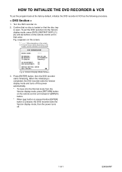
...To put the program back at the factory-default, initialize the DVD recorder & VCR as the following procedure. < DVD Section > 1. Press [ENTER] button, then the DVD recorder starts initializing. Turn the DVD recorder on the models, and this indication is one example. Confirm that no... on the screen. *1: "*******" differs depending on the models. *2: Firmware Version differs depending on . 2. HOW TO INITIALIZE THE DVD RECORDER & VCR To put the DVD recorder into the Normal mode from the Version display mode, press [RETURN] button on the remote control unit instead of [ENTER] button. ...
...To put the program back at the factory-default, initialize the DVD recorder & VCR as the following procedure. < DVD Section > 1. Press [ENTER] button, then the DVD recorder starts initializing. Turn the DVD recorder on the models, and this indication is one example. Confirm that no... on the screen. *1: "*******" differs depending on the models. *2: Firmware Version differs depending on . 2. HOW TO INITIALIZE THE DVD RECORDER & VCR To put the DVD recorder into the Normal mode from the Version display mode, press [RETURN] button on the remote control unit instead of [ENTER] button. ...
Service Manual
Page 21
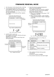
To put the DVD recorder into the memory Firmware 2 Updating... Fig. WL5T*****H1E Current F/W version is displayed. a Version Up Mode Screen 4. Fig. Disc name is displayed. d is finished, the tray .... c Update Disc Screen Fig. Firmware Update Failure Failed in Version Up Mode 3. Pull out the AC code once, then insert it again. 1-9-1 E9KGAFW The DVD recorder starts updating. When there is one example. FIRMWARE RENEWAL MODE 1. b appears on the VFD. * Firmware Version differs depending on the models, and this indication is...
To put the DVD recorder into the memory Firmware 2 Updating... Fig. WL5T*****H1E Current F/W version is displayed. a Version Up Mode Screen 4. Fig. Disc name is displayed. d is finished, the tray .... c Update Disc Screen Fig. Firmware Update Failure Failed in Version Up Mode 3. Pull out the AC code once, then insert it again. 1-9-1 E9KGAFW The DVD recorder starts updating. When there is one example. FIRMWARE RENEWAL MODE 1. b appears on the VFD. * Firmware Version differs depending on the models, and this indication is...
Service Manual
Page 36
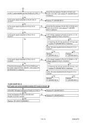
... IC2101? Is the "H" pulse inputted into Pin(3,13) of No IC2101? Replace P1 (BOARD MCV). FLOW CHART NO.12 Hi-Fi audio can not be recorded normally. (E-E mode is normal.) No Is the REC FM signal outputted to Pin(78, 80) of No IC1451? Replace P1 (BOARD MCV). 1-10-15 E9KGATR...
... IC2101? Is the "H" pulse inputted into Pin(3,13) of No IC2101? Replace P1 (BOARD MCV). FLOW CHART NO.12 Hi-Fi audio can not be recorded normally. (E-E mode is normal.) No Is the REC FM signal outputted to Pin(78, 80) of No IC1451? Replace P1 (BOARD MCV). 1-10-15 E9KGATR...
Service Manual
Page 37
... Pin(10) of IC1301 and Pin(4) of IC1301, and replace P1 (BOARD MCV) if defective. FLOW CHART NO.13 Hi-Fi audio can not be recorded normally in the linear audio mode. (E-E mode is normal.) Yes Is the audio signal supplied to Pin(6) of IC1301? Check the line between Pin(39...
... Pin(10) of IC1301 and Pin(4) of IC1301, and replace P1 (BOARD MCV) if defective. FLOW CHART NO.13 Hi-Fi audio can not be recorded normally in the linear audio mode. (E-E mode is normal.) Yes Is the audio signal supplied to Pin(6) of IC1301? Check the line between Pin(39...
Service Manual
Page 38
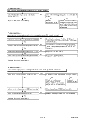
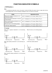
...00 : 00 A D SP 0 : 00 : 00 Recording mode Elapsed time Fig. 1 When tape loading mechanism is not functioning correctly Recording mode Elapsed time P-ON Power safety detection Fig. 4 A T SP 0 : 00 : 00 Recording mode Elapsed time Fig. 2 When cassette loading mechanism is not... tape loading mechanism is not functioning correctly A P SP 0 : 00 : 00 Recording mode Elapsed time Fig. 5 A C SP 0 : 00 : 00 Recording mode Elapsed time Fig. 3 1-11-1 E9KGAFIS FUNCTION INDICATOR SYMBOLS < VCR Section > Note: If a mechanical malfunction occurs, the power is displayed on the ...
...00 : 00 A D SP 0 : 00 : 00 Recording mode Elapsed time Fig. 1 When tape loading mechanism is not functioning correctly Recording mode Elapsed time P-ON Power safety detection Fig. 4 A T SP 0 : 00 : 00 Recording mode Elapsed time Fig. 2 When cassette loading mechanism is not... tape loading mechanism is not functioning correctly A P SP 0 : 00 : 00 Recording mode Elapsed time Fig. 5 A C SP 0 : 00 : 00 Recording mode Elapsed time Fig. 3 1-11-1 E9KGAFIS FUNCTION INDICATOR SYMBOLS < VCR Section > Note: If a mechanical malfunction occurs, the power is displayed on the ...
Service Manual
Page 39
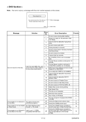
...Difference in the address and can not get Stream ID of VR Mode. 6 24 The disc except for the correspondence to You cannot record copy be recorded on this disc as Power Calibration Area is not readable." - 14 Cannot write the data after recovering SMALL VMGI. - 15 Cannot... "ATAPI is full. prohibited programs. 25 During the Macrovision picture input. 11 26 During the CGMS picture input. 12 This program is not recordable Set "DVD-RW Recording in PCA Full (DVD_R). - 19 Safety Stop occurs during data reading. - 2 There is no reply for 15 seconds in Test Unit ...
...Difference in the address and can not get Stream ID of VR Mode. 6 24 The disc except for the correspondence to You cannot record copy be recorded on this disc as Power Calibration Area is not readable." - 14 Cannot write the data after recovering SMALL VMGI. - 15 Cannot... "ATAPI is full. prohibited programs. 25 During the Macrovision picture input. 11 26 During the CGMS picture input. 12 This program is not recordable Set "DVD-RW Recording in PCA Full (DVD_R). - 19 Safety Stop occurs during data reading. - 2 There is no reply for 15 seconds in Test Unit ...
Service Manual
Page 40
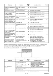
... chapter marks. 44 The 254 chapter has been reached. (+VR Format Disc) 10 This program is not displayed. 1 / 1 A program with a record tab. - Turn the power on this disc as Power Calibration Area is Insert a new disc. 35 PCA is Full. (in +VR mode. Delete... overlapping. - Set the timer programming before the start time. - - Release the finalizing for new recording) Insert the recordable disc with enough recording space. 30 No available recording space. 5 You cannot record more than 99 titles on one of the following error numbers (40 to 42) or the above...
... chapter marks. 44 The 254 chapter has been reached. (+VR Format Disc) 10 This program is not displayed. 1 / 1 A program with a record tab. - Turn the power on this disc as Power Calibration Area is Insert a new disc. 35 PCA is Full. (in +VR mode. Delete... overlapping. - Set the timer programming before the start time. - - Release the finalizing for new recording) Insert the recordable disc with enough recording space. 30 No available recording space. 5 You cannot record more than 99 titles on one of the following error numbers (40 to 42) or the above...
Service Manual
Page 77
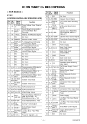
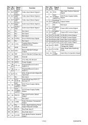
... Serial Clock 20 OUT YCA-SDA YCA IC Serial Data 21 OUT YCA-CS YCA IC Chip Select 22 IN RECSAF-SW Recording Safety SW Detect (With Record tab = "L"/ Without Record tab = "H") 23 OUT RF-SW Video Head Switching Pulse 24 OUT D-V SYNC Dummy V-sync Output 25 IN RESET System Reset... Signal (Reset="L") 26 OUT LM-FWD/ REV Loading Motor FWD/ REV Output 27 OUT P-ON-L Power On Signal to VCR Micro Controller Communication of...
... Serial Clock 20 OUT YCA-SDA YCA IC Serial Data 21 OUT YCA-CS YCA IC Chip Select 22 IN RECSAF-SW Recording Safety SW Detect (With Record tab = "L"/ Without Record tab = "H") 23 OUT RF-SW Video Head Switching Pulse 24 OUT D-V SYNC Dummy V-sync Output 25 IN RESET System Reset... Signal (Reset="L") 26 OUT LM-FWD/ REV Loading Motor FWD/ REV Output 27 OUT P-ON-L Power On Signal to VCR Micro Controller Communication of...
Service Manual
Page 78
...100 IN H-ACOMP Head Amp Comparator Signal 1-16-2 E9KGAPIN AC Ground 73 IN ADVV Power Supply 74 IN/ OUT CTL (+) Playback/Record Control Signal (+) 75 IN/ OUT CTL (-) Playback/Record Control Signal (-) 76 OUT CTL Amp. NU 64 - NU Not Used Not Used 65 IN D-PFG Drum PG/FG Input ... Not Used 78 IN Hi-Fi/ NOR-IN Audio Mode Input HiFi="L"/ Normal="H" 79 IN DVD POWERSAFETY DVD Power Supply Safety Signal 80 IN VCR POWERSAFETY VCR Power Supply Safety Signal 81 IN END-S Tape End Position Detect Signal 82 - NU Not Used 83 IN V-ENV 84 IN PGDELAY Video Envelope...
...100 IN H-ACOMP Head Amp Comparator Signal 1-16-2 E9KGAPIN AC Ground 73 IN ADVV Power Supply 74 IN/ OUT CTL (+) Playback/Record Control Signal (+) 75 IN/ OUT CTL (-) Playback/Record Control Signal (-) 76 OUT CTL Amp. NU 64 - NU Not Used Not Used 65 IN D-PFG Drum PG/FG Input ... Not Used 78 IN Hi-Fi/ NOR-IN Audio Mode Input HiFi="L"/ Normal="H" 79 IN DVD POWERSAFETY DVD Power Supply Safety Signal 80 IN VCR POWERSAFETY VCR Power Supply Safety Signal 81 IN END-S Tape End Position Detect Signal 82 - NU Not Used 83 IN V-ENV 84 IN PGDELAY Video Envelope...


