
Easy Smart SwitchUN User Guide
Page 3
......39 Testing Cables...41 Configuring Loop Prevention...43 Appendix: Default Parameters...44 Configuring VLAN Overview...46 Configuring MTU VLAN...48 Configuring Port Based VLAN...49 Configuring 802.1Q VLAN...50 Configuring the VLAN...50 Configuring the PVID...52 Configuration Example for 802.1Q VLAN...53 Network Requirements...53 Configuration Scheme...53 Configuration Steps...55 Appendix: Default...
......39 Testing Cables...41 Configuring Loop Prevention...43 Appendix: Default Parameters...44 Configuring VLAN Overview...46 Configuring MTU VLAN...48 Configuring Port Based VLAN...49 Configuring 802.1Q VLAN...50 Configuring the VLAN...50 Configuring the PVID...52 Configuration Example for 802.1Q VLAN...53 Network Requirements...53 Configuration Scheme...53 Configuration Steps...55 Appendix: Default...

Easy Smart SwitchUN User Guide
Page 8
...;■ Traffic monitoring: Port mirroring, loop prevention and cable test enable the administrator to monitor traffic of the network effectively. ■■ VLAN: MTU VLAN, Port based VLAN and 802.1Q VLAN can supply power to the actual web interface. Storm control helps avoid network broadcast storm. ■■ PoE: PoE (Power over twisted...
...;■ Traffic monitoring: Port mirroring, loop prevention and cable test enable the administrator to monitor traffic of the network effectively. ■■ VLAN: MTU VLAN, Port based VLAN and 802.1Q VLAN can supply power to the actual web interface. Storm control helps avoid network broadcast storm. ■■ PoE: PoE (Power over twisted...

Easy Smart SwitchUN User Guide
Page 31
... Message Suppression Enable or disable Report Message Suppression globally. IP Address Displays the IP address of the multicast group. VLAN ID Displays the VLAN ID of a multicast group should be included in the same VLAN. Figure 3-1 Configuring IGMP Snooping Follow these steps to the IGMP querier. 2) In the table below, you can view...
... Message Suppression Enable or disable Report Message Suppression globally. IP Address Displays the IP address of the multicast group. VLAN ID Displays the VLAN ID of a multicast group should be included in the same VLAN. Figure 3-1 Configuring IGMP Snooping Follow these steps to the IGMP querier. 2) In the table below, you can view...

Easy Smart SwitchUN User Guide
Page 34
... multicast streams sent to port 1, port 2 and port 3 respectively. Port 4 is the router port connected to the same VLAN. ■■ Enable IGMP Snooping. Add the three member ports and the router port to the multicast querier. Switching 5 ... Example for Basic IGMP Snooping Source Internet Querier Port 1 Port 4 Port 3 Port 2 Host B Receiver Host C Receiver VLAN 2 Host D Receiver 5.1.2 Configuration Scheme ■■ Configure 802.1Q VLAN. All of the switch. Figure 5-1 Network Topology for Configuring IGMP Snooping 5.1.1 Network Requirements Host B, Host C and Host ...
... multicast streams sent to port 1, port 2 and port 3 respectively. Port 4 is the router port connected to the same VLAN. ■■ Enable IGMP Snooping. Add the three member ports and the router port to the multicast querier. Switching 5 ... Example for Basic IGMP Snooping Source Internet Querier Port 1 Port 4 Port 3 Port 2 Host B Receiver Host C Receiver VLAN 2 Host D Receiver 5.1.2 Configuration Scheme ■■ Configure 802.1Q VLAN. All of the switch. Figure 5-1 Network Topology for Configuring IGMP Snooping 5.1.1 Network Requirements Host B, Host C and Host ...

Easy Smart SwitchUN User Guide
Page 35
Figure 5-2 Configuring 802.1Q VLAN User Guide 31 Select port 4 as VLAN2. Click Apply. Specify the VLAN name as a tagged port. Click Add/Modify. Select port 1, port 2, port 3 as 2. Specify the VLAN ID as untagged ports. Select the 802.1Q VLAN Configuration as Enable. Switching Configuration Examples Demonstrated with TL-SG1016PE, the following section provides configuration steps. 5.1.3 Configuration Steps 1) Choose the menu VLAN > 802.1Q VLAN to load the following page.
Figure 5-2 Configuring 802.1Q VLAN User Guide 31 Select port 4 as VLAN2. Click Apply. Specify the VLAN name as a tagged port. Click Add/Modify. Select port 1, port 2, port 3 as 2. Specify the VLAN ID as untagged ports. Select the 802.1Q VLAN Configuration as Enable. Switching Configuration Examples Demonstrated with TL-SG1016PE, the following section provides configuration steps. 5.1.3 Configuration Steps 1) Choose the menu VLAN > 802.1Q VLAN to load the following page.

Easy Smart SwitchUN User Guide
Page 36
..., we bundle port 1, port 2 and port 3 of data transmission, you can bundle multiple physical ports into one logical interface. Switching Configuration Examples 2) Choose the menu VLAN > 802.1Q PVID Setting to load the following page. User Guide 32 Click Apply. Click Apply. Select port 1, port 2, port 3 and port 4, and specify the...
..., we bundle port 1, port 2 and port 3 of data transmission, you can bundle multiple physical ports into one logical interface. Switching Configuration Examples 2) Choose the menu VLAN > 802.1Q PVID Setting to load the following page. User Guide 32 Click Apply. Click Apply. Select port 1, port 2, port 3 and port 4, and specify the...

Easy Smart SwitchUN User Guide
Page 49
Appendix: Default Parameters Configuring MTU VLAN 3. Configuring 802.1Q VLAN 5. Part 5 Configuring VLAN CHAPTERS 1. Configuring Port Based VLAN 4. Configuration Example for 802.1Q VLAN 6. Overview 2.
Appendix: Default Parameters Configuring MTU VLAN 3. Configuring 802.1Q VLAN 5. Part 5 Configuring VLAN CHAPTERS 1. Configuring Port Based VLAN 4. Configuration Example for 802.1Q VLAN 6. Overview 2.

Easy Smart SwitchUN User Guide
Page 50
... cannot communicate with each port can communicate with the device connected to determine which will build up several VLANs, and all VLAN traffic remains within its VLAN. Figure 1-1 Untagged and Tagged Data Frame Traditional Ethernet data frame (Untagged Frame) Destination Source Length/Type...in the switch, so the device connected to the traditional Ethernet data frame (Untagged Frame), the VLAN data frame (Tagged Frame) adds a VLAN tag. Configuring VLAN Overview 1 Overview VLAN (Virtual Local Area Network) is usually applied in the following figure shows, compared to the uplink...
... cannot communicate with each port can communicate with the device connected to determine which will build up several VLANs, and all VLAN traffic remains within its VLAN. Figure 1-1 Untagged and Tagged Data Frame Traditional Ethernet data frame (Untagged Frame) Destination Source Length/Type...in the switch, so the device connected to the traditional Ethernet data frame (Untagged Frame), the VLAN data frame (Tagged Frame) adds a VLAN tag. Configuring VLAN Overview 1 Overview VLAN (Virtual Local Area Network) is usually applied in the following figure shows, compared to the uplink...

Easy Smart SwitchUN User Guide
Page 51
Configuring VLAN Overview switch will be disabled automatically and the corresponding VLAN configuration will first insert a VLAN tag to 32 VLANs simultaneously. Note: ●● The switch works in one and only one VLAN mode at any time. User Guide 47 When a specific VLAN mode is enabled, the other two VLAN modes will be lost. ●● The switch supports up to the frame, using the PVID (Port VLAN ID) of the port as its VID, and then forward it as a tagged frame.
Configuring VLAN Overview switch will be disabled automatically and the corresponding VLAN configuration will first insert a VLAN tag to 32 VLANs simultaneously. Note: ●● The switch works in one and only one VLAN mode at any time. User Guide 47 When a specific VLAN mode is enabled, the other two VLAN modes will be lost. ●● The switch supports up to the frame, using the PVID (Port VLAN ID) of the port as its VID, and then forward it as a tagged frame.

Easy Smart SwitchUN User Guide
Page 52
... port from the drop-down list. The uplink port will build up several VLANs with each of the other ports. User Guide 48 Configuring VLAN Configuring MTU VLAN 2 Configuring MTU VLAN Choose the menu VLAN > MTU VLAN to configure MTU VLAN: 1) Select MTU VLAN configuration as Enable. Figure 2-1 Configuring MTU VLAN Follow these steps to load the following page.
... port from the drop-down list. The uplink port will build up several VLANs with each of the other ports. User Guide 48 Configuring VLAN Configuring MTU VLAN 2 Configuring MTU VLAN Choose the menu VLAN > MTU VLAN to configure MTU VLAN: 1) Select MTU VLAN configuration as Enable. Figure 2-1 Configuring MTU VLAN Follow these steps to load the following page.

Easy Smart SwitchUN User Guide
Page 53
... port is removed from all the other VLANs, it is added to load the following page. User Guide 49 Configuring VLAN Configuring Port Based VLAN 3 Configuring Port Based VLAN Choose the menu VLAN > Port Based VLAN to VLAN 1 automatically. ●● VLAN 1 includes at least one port and cannot... be deleted. Figure 3-1 Configuring Port Based VLAN Follow these step to . ...
... port is removed from all the other VLANs, it is added to load the following page. User Guide 49 Configuring VLAN Configuring Port Based VLAN 3 Configuring Port Based VLAN Choose the menu VLAN > Port Based VLAN to VLAN 1 automatically. ●● VLAN 1 includes at least one port and cannot... be deleted. Figure 3-1 Configuring Port Based VLAN Follow these step to . ...

Easy Smart SwitchUN User Guide
Page 54
Figure 4-1 Configuring 802.1Q VLAN User Guide 50 Configuring VLAN Configuring 802.1Q VLAN 4 Configuring 802.1Q VLAN To complete the 802.1Q configuration, follow these steps: 1) Configure the VLAN, including creating a VLAN and adding the ports to the VLAN. 2) Configure the PVID. 4.1 Configuring the VLAN Choose the menu VLAN > 802.1Q VLAN to load the following page.
Figure 4-1 Configuring 802.1Q VLAN User Guide 50 Configuring VLAN Configuring 802.1Q VLAN 4 Configuring 802.1Q VLAN To complete the 802.1Q configuration, follow these steps: 1) Configure the VLAN, including creating a VLAN and adding the ports to the VLAN. 2) Configure the PVID. 4.1 Configuring the VLAN Choose the menu VLAN > 802.1Q VLAN to load the following page.

Easy Smart SwitchUN User Guide
Page 55
... Enable or disable the 802.1Q VLAN mode. 2) Enter a VLAN ID and a VLAN name for identification. VLAN ID Enter a VLAN ID, which rages from 1 to the created VLAN based on the network topology. VLAN Name Enter a VLAN name for identification. Untagged / Tagged / Not Member Set the port as ..., hyphens and underlines only. The VLAN name should not be deleted. A tagged port will forward frames after removing the VLAN tags. Configuring VLAN Configuring 802.1Q VLAN Follow these steps to configure the VLAN: 1) Select the 802.1Q VLAN Configuration as Untagged. User Guide 51...
... Enable or disable the 802.1Q VLAN mode. 2) Enter a VLAN ID and a VLAN name for identification. VLAN ID Enter a VLAN ID, which rages from 1 to the created VLAN based on the network topology. VLAN Name Enter a VLAN name for identification. Untagged / Tagged / Not Member Set the port as ..., hyphens and underlines only. The VLAN name should not be deleted. A tagged port will forward frames after removing the VLAN tags. Configuring VLAN Configuring 802.1Q VLAN Follow these steps to configure the VLAN: 1) Select the 802.1Q VLAN Configuration as Untagged. User Guide 51...

Easy Smart SwitchUN User Guide
Page 56
Figure 4-2 Configuring 802.1Q PVID Follow these steps to configure the PVID: 1) Select the ports and set the PVID for the ports. Note: ●● The PVID configuration will take effect only when 802.1Q VLAN mode is enabled. ●● You can specify a PVID only when the corresponding VLAN exists. PVID Set the PVID for the ports. Configuring VLAN Configuring 802.1Q VLAN 4.2 Configuring the PVID Choose the menu VLAN > 802.1Q PVID Setting to 4094. 2) Click Apply. The PVID ranges from 1 to load the following page. User Guide 52
Figure 4-2 Configuring 802.1Q PVID Follow these steps to configure the PVID: 1) Select the ports and set the PVID for the ports. Note: ●● The PVID configuration will take effect only when 802.1Q VLAN mode is enabled. ●● You can specify a PVID only when the corresponding VLAN exists. PVID Set the PVID for the ports. Configuring VLAN Configuring 802.1Q VLAN 4.2 Configuring the PVID Choose the menu VLAN > 802.1Q PVID Setting to 4094. 2) Click Apply. The PVID ranges from 1 to load the following page. User Guide 52

Easy Smart SwitchUN User Guide
Page 57
... of different departments cannot. It's required that: ■■ Hosts of both switches. ■■ Create VLAN 2. On Switch A, add port 2 and port 4 to VLAN 2, while on both departments can access the internet. ■■ Hosts of the same department can communicate with... other, but hosts of the same department are located in different places and connected to VLAN 2. User Guide 53 Configuring VLAN Configuration Example for 802.1Q VLAN 5 Configuration Example for 802.1Q VLAN 5.1 Network Requirements As the following figure shows, a company has two departments. Figure 5-1...
... of different departments cannot. It's required that: ■■ Hosts of both switches. ■■ Create VLAN 2. On Switch A, add port 2 and port 4 to VLAN 2, while on both departments can access the internet. ■■ Hosts of the same department can communicate with... other, but hosts of the same department are located in different places and connected to VLAN 2. User Guide 53 Configuring VLAN Configuration Example for 802.1Q VLAN 5 Configuration Example for 802.1Q VLAN 5.1 Network Requirements As the following figure shows, a company has two departments. Figure 5-1...
Easy Smart SwitchUN User Guide
Page 58
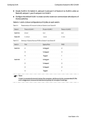
Table 5-1 Relationships of VLANs on Switch A and Switch B. Configuring VLAN Configuration Example for 802.1Q VLAN ■■ Create VLAN 3. Table 5-1 and 5-2 show configurations of Ports and VLANs on each switch. User Guide 54 Switch Ports in VLAN 1 Ports in VLAN 2 Ports in VLAN 3 Switch A 2, 3, 4 2, 4 3,... 4 1, 2 ,4 1, 3, 4 Table 5-2 Settings of the two switches. On Switch A, add port 3 and port 4 of Switch A to VLAN 3, while on Switch A and Switch B Switch Port Egress Rule PVID Switch A 2 Untagged 2 3 Untagged 3 4 Tagged 1 Switch B 1 Untagged...
Table 5-1 Relationships of VLANs on Switch A and Switch B. Configuring VLAN Configuration Example for 802.1Q VLAN ■■ Create VLAN 3. Table 5-1 and 5-2 show configurations of Ports and VLANs on each switch. User Guide 54 Switch Ports in VLAN 1 Ports in VLAN 2 Ports in VLAN 3 Switch A 2, 3, 4 2, 4 3,... 4 1, 2 ,4 1, 3, 4 Table 5-2 Settings of the two switches. On Switch A, add port 3 and port 4 of Switch A to VLAN 3, while on Switch A and Switch B Switch Port Egress Rule PVID Switch A 2 Untagged 2 3 Untagged 3 4 Tagged 1 Switch B 1 Untagged...

Easy Smart SwitchUN User Guide
Page 59
Here we take Switch A for 802.1Q VLAN 5.3 Configuration Steps Demonstrated with TL-SG1016PE, the following page. The configuration steps on both switches are similar. Figure 5-2 Configuring 802.1Q VLAN User Guide 55 Configuring VLAN Configuration Example for example. 1) Choose the menu VLAN > 802.1Q VLAN to load the following section provides configuration steps. Select 802.1Q VLAN configuration as Enable. Click Apply.
Here we take Switch A for 802.1Q VLAN 5.3 Configuration Steps Demonstrated with TL-SG1016PE, the following page. The configuration steps on both switches are similar. Figure 5-2 Configuring 802.1Q VLAN User Guide 55 Configuring VLAN Configuration Example for example. 1) Choose the menu VLAN > 802.1Q VLAN to load the following section provides configuration steps. Select 802.1Q VLAN configuration as Enable. Click Apply.

Easy Smart SwitchUN User Guide
Page 60
Specify VLAN ID as 2, add port 2 to the VLAN as an untagged port, and add port 4 to load the following page and create VLAN 2. Configuring VLAN Configuration Example for 802.1Q VLAN 2) Choose the menu VLAN > 802.1Q VLAN to the VLAN as a tagged port. Click Add/Modify. Figure 5-3 Creating VLAN 2 and Adding Ports to the VLAN User Guide 56
Specify VLAN ID as 2, add port 2 to the VLAN as an untagged port, and add port 4 to load the following page and create VLAN 2. Configuring VLAN Configuration Example for 802.1Q VLAN 2) Choose the menu VLAN > 802.1Q VLAN to the VLAN as a tagged port. Click Add/Modify. Figure 5-3 Creating VLAN 2 and Adding Ports to the VLAN User Guide 56

Easy Smart SwitchUN User Guide
Page 61
Specify VLAN ID as 3, add port 3 to the VLAN as an untagged port, and add port 4 to the VLAN as 2 and click Apply. Specify the PVID of port 3 as 3 and click Apply. Click Add/Modify. Figure 5-4 Creating VLAN 3 and Adding Ports to the VLAN 4) Choose the menu VLAN > 802.1Q VLAN PVID Setting to load the following page and create VLAN 3. Specify the PVID of port 2 as a tagged port. User Guide 57 Configuring VLAN Configuration Example for 802.1Q VLAN 3) Choose the menu VLAN > 802.1Q VLAN to load the following page.
Specify VLAN ID as 3, add port 3 to the VLAN as an untagged port, and add port 4 to the VLAN as 2 and click Apply. Specify the PVID of port 3 as 3 and click Apply. Click Add/Modify. Figure 5-4 Creating VLAN 3 and Adding Ports to the VLAN 4) Choose the menu VLAN > 802.1Q VLAN PVID Setting to load the following page and create VLAN 3. Specify the PVID of port 2 as a tagged port. User Guide 57 Configuring VLAN Configuration Example for 802.1Q VLAN 3) Choose the menu VLAN > 802.1Q VLAN to load the following page.

Easy Smart SwitchUN User Guide
Page 62
Configuring VLAN Figure 5-5 Configuring 802.1Q PVID Configuration Example for 802.1Q VLAN User Guide 58
Configuring VLAN Figure 5-5 Configuring 802.1Q PVID Configuration Example for 802.1Q VLAN User Guide 58

