
User Guide
Page 3
http://www.tp-link.com I COPYRIGHT & TRADEMARKS Specifications are trademarks or registered trademarks of the specifications may be reproduced in any form or by any means or used to change without permission from TP-LINK TECHNOLOGIES CO., LTD. Other brands and product names are subject to make any derivative such as translation, transformation, or adaptation without notice. Copyright © 2013 TP-LINK TECHNOLOGIES CO., LTD. No part of their respective holders. All rights reserved. is a registered trademark of TP-LINK TECHNOLOGIES CO., LTD.
http://www.tp-link.com I COPYRIGHT & TRADEMARKS Specifications are trademarks or registered trademarks of the specifications may be reproduced in any form or by any means or used to change without permission from TP-LINK TECHNOLOGIES CO., LTD. Other brands and product names are subject to make any derivative such as translation, transformation, or adaptation without notice. Copyright © 2013 TP-LINK TECHNOLOGIES CO., LTD. No part of their respective holders. All rights reserved. is a registered trademark of TP-LINK TECHNOLOGIES CO., LTD.

User Guide
Page 4
..., which can radiate radio frequency energy and, if not installed and used in accordance with the instructions, may cause undesired operation. This device complies with part 15 of the following two conditions: 1) This device may...turning the equipment off and on a circuit different from that interference will not occur in a particular installation. Operation is encouraged to try to the following measures: Reorient or relocate the receiving antenna. Increase the separation between the equipment and receiver. Connect the equipment into an outlet on , the user...
..., which can radiate radio frequency energy and, if not installed and used in accordance with the instructions, may cause undesired operation. This device complies with part 15 of the following two conditions: 1) This device may...turning the equipment off and on a circuit different from that interference will not occur in a particular installation. Operation is encouraged to try to the following measures: Reorient or relocate the receiving antenna. Increase the separation between the equipment and receiver. Connect the equipment into an outlet on , the user...

User Guide
Page 5
In a domestic environment, this product may cause radio interference, in a wet basement or near a swimming pool. There may be required to operate the equipment. CE Mark Warning This is a class B product. Avoid using this product near water, for compliance could void the user's authority to take adequate measures. Any changes or modifications not expressly approved by the party responsible for example, in which case the user may be a remote risk of electric shock from lightning. Safety Notices Cautions: Do not use this product during an electrical storm. III
In a domestic environment, this product may cause radio interference, in a wet basement or near a swimming pool. There may be required to operate the equipment. CE Mark Warning This is a class B product. Avoid using this product near water, for compliance could void the user's authority to take adequate measures. Any changes or modifications not expressly approved by the party responsible for example, in which case the user may be a remote risk of electric shock from lightning. Safety Notices Cautions: Do not use this product during an electrical storm. III
User Guide
Page 6
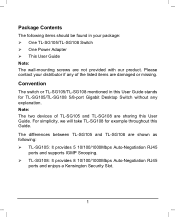
... Power Adapter This User Guide Note: The wall-mounting screws are damaged or missing. Package Contents The following : TL-SG105: It provides 5 10/100/1000Mbps Auto-Negotiation RJ45 ports and supports IGMP Snooping. TL-SG108: It provides 8 10/100/1000Mbps Auto-Negotiation RJ45 ports and enjoys a Kensington Security Slot. 1 For simplicity, we will take TL-SG108 for example throughout this User Guide stands for TL-SG105/TL-SG108 5/8-port Gigabit Desktop Switch...
... Power Adapter This User Guide Note: The wall-mounting screws are damaged or missing. Package Contents The following : TL-SG105: It provides 5 10/100/1000Mbps Auto-Negotiation RJ45 ports and supports IGMP Snooping. TL-SG108: It provides 8 10/100/1000Mbps Auto-Negotiation RJ45 ports and enjoys a Kensington Security Slot. 1 For simplicity, we will take TL-SG108 for example throughout this User Guide stands for TL-SG105/TL-SG108 5/8-port Gigabit Desktop Switch...

User Guide
Page 7
... to quickly detect and correct problems on all ports eliminates the demand of the Product Powered by forwarding and filtering packets at full wire-speed for maximum throughput. Each port can be simply plugged into a server, a hub, a router, a switch or a PC, using the straight cable or crossover cable. The switch automatically powers down , budgets power output for choosing the TL-SG105/TL-SG108 5/8-port Gigabit Desktop Switch. 1.1 Overview of crossover cable or Uplink port. Diagnostic LEDs which display link status...
... to quickly detect and correct problems on all ports eliminates the demand of the Product Powered by forwarding and filtering packets at full wire-speed for maximum throughput. Each port can be simply plugged into a server, a hub, a router, a switch or a PC, using the straight cable or crossover cable. The switch automatically powers down , budgets power output for choosing the TL-SG105/TL-SG108 5/8-port Gigabit Desktop Switch. 1.1 Overview of crossover cable or Uplink port. Diagnostic LEDs which display link status...

User Guide
Page 8
... monitoring power, link, speed and activity External power adapter supply 3 1.2 Features Supports Green Ethernet technology to implement power saving features Complies with autolearning and auto-aging Supports for Jumbo frames of up to 9KB LED indicators for maximum throughput IGMP snooping allows the forwarding of multicast packets such as streaming audio and video, without increasing network broadcast congestion Supports QoS (802.1p/Q-based) function 4K entry MAC address table of TL-SG105/TL...
... monitoring power, link, speed and activity External power adapter supply 3 1.2 Features Supports Green Ethernet technology to implement power saving features Complies with autolearning and auto-aging Supports for Jumbo frames of up to 9KB LED indicators for maximum throughput IGMP snooping allows the forwarding of multicast packets such as streaming audio and video, without increasing network broadcast congestion Supports QoS (802.1p/Q-based) function 4K entry MAC address table of TL-SG105/TL...

User Guide
Page 9
... Figure 2-1 TL-SG108 Switch Front Panel The following parts are located on the front panel: Ports (1-8): The TL-SG108 switch is equipped with 8 10/100/ 1000Mbps Auto-Sensing RJ45 ports where you will light solid green when a 1000Mbps device is connected to the port. It flashes green when data is being transmitted or received on the working connection. Note: The LEDs' description above explains the device's working status can...
... Figure 2-1 TL-SG108 Switch Front Panel The following parts are located on the front panel: Ports (1-8): The TL-SG108 switch is equipped with 8 10/100/ 1000Mbps Auto-Sensing RJ45 ports where you will light solid green when a 1000Mbps device is connected to the port. It flashes green when data is being transmitted or received on the working connection. Note: The LEDs' description above explains the device's working status can...

User Guide
Page 10
... TL-SG108 switch. Chapter 3 Installation The switch can be either located on a desktop or mounted on a wall. 3.1 Mounting the Switch on a Desk To locate the switch on a desktop, please follow these steps: 1) Place the switch on a flat desk. 2) Inspect the Power Adapter carefully and make sure that it is where you will connect the power adapter. 2.2 Rear Panel Figure 2-2 TL-SG108 Switch Rear Panel The following parts...
... TL-SG108 switch. Chapter 3 Installation The switch can be either located on a desktop or mounted on a wall. 3.1 Mounting the Switch on a Desk To locate the switch on a desktop, please follow these steps: 1) Place the switch on a flat desk. 2) Inspect the Power Adapter carefully and make sure that it is where you will connect the power adapter. 2.2 Rear Panel Figure 2-2 TL-SG108 Switch Rear Panel The following parts...

User Guide
Page 11
To mount the switch on a wall, please follow the steps below. 1) Drill two holes into each hole and leave a part of the switch. Figure 3-1 Mounting the Switch on a Wall 6 To ensure the stable cable connection, please keep the switch horizontal on the desktop, with white cover facing up. 3.2 Mounting the Switch on a Wall There are two wall-mounting slots on the bottom panel of its head exposed. 2) Place the two wall-mounting slots over the screws and slide the switch down to fasten it. Insert a screw into the wall.
To mount the switch on a wall, please follow the steps below. 1) Drill two holes into each hole and leave a part of the switch. Figure 3-1 Mounting the Switch on a Wall 6 To ensure the stable cable connection, please keep the switch horizontal on the desktop, with white cover facing up. 3.2 Mounting the Switch on a Wall There are two wall-mounting slots on the bottom panel of its head exposed. 2) Place the two wall-mounting slots over the screws and slide the switch down to fasten it. Insert a screw into the wall.

User Guide
Page 12
Note:! 3.3 Power On Power on the switch and it will respond as follows: Name Power LEDs (port 1-8) Time All the time 1st second 2nd second 3rd second~ Status On On Off Off On Indication Power on N/A N/A No device connected to the corresponding port. There is a 10/100/1000Mbps device connected to the corresponding port. If the LED indicators don't respond as described above, please check the power supply and its LED indicators will automatically initialize and its connection. 7
Note:! 3.3 Power On Power on the switch and it will respond as follows: Name Power LEDs (port 1-8) Time All the time 1st second 2nd second 3rd second~ Status On On Off Off On Indication Power on N/A N/A No device connected to the corresponding port. There is a 10/100/1000Mbps device connected to the corresponding port. If the LED indicators don't respond as described above, please check the power supply and its LED indicators will automatically initialize and its connection. 7
User Guide
Page 14
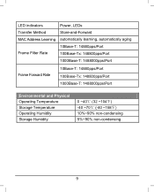
LED indicators Transfer Method MAC Address Learning Frame Filter Rate Power, LEDs Store-and-Forward automatically learning, automatically aging 10Base-T: 14880pps/Port 100Base-Tx: 148800pps/Port 1000Base-T: 1488000pps/Port Frame Forward Rate 10Base-T: 14880pps/Port 100Base-Tx: 148800pps/Port 1000Base-T: 1488000pps/Port Environmental and Physical Operating Temperature Storage Temperature Operating Humidity Storage Humidity 0 ~40℃ (32 ~104℉) -40 ~70℃ (-40 ~158℉) 10%~90% non-condensing 5%~90% non-condensing 9
LED indicators Transfer Method MAC Address Learning Frame Filter Rate Power, LEDs Store-and-Forward automatically learning, automatically aging 10Base-T: 14880pps/Port 100Base-Tx: 148800pps/Port 1000Base-T: 1488000pps/Port Frame Forward Rate 10Base-T: 14880pps/Port 100Base-Tx: 148800pps/Port 1000Base-T: 1488000pps/Port Environmental and Physical Operating Temperature Storage Temperature Operating Humidity Storage Humidity 0 ~40℃ (32 ~104℉) -40 ~70℃ (-40 ~158℉) 10%~90% non-condensing 5%~90% non-condensing 9

User Guide
Page 15
Appendix B: Troubleshooting 1. Make sure the cable is ON. 2. The Link/Act LED is not lit when a device is connected to the corresponding port Check to see if the AC power cord is connected to see if the cable connectors are firmly plugged into the switch and the device, and verify the connected device is turned on and working well. The Power LED is not lit Check to the switch properly, and make sure the power source is not longer than 100 meters (328 feet). 10
Appendix B: Troubleshooting 1. Make sure the cable is ON. 2. The Link/Act LED is not lit when a device is connected to the corresponding port Check to see if the AC power cord is connected to see if the cable connectors are firmly plugged into the switch and the device, and verify the connected device is turned on and working well. The Power LED is not lit Check to the switch properly, and make sure the power source is not longer than 100 meters (328 feet). 10


