
Startup Guide
Page 27
... by turning the equipment off , or disconnect the power plug. Connect the equipment into an outlet on , the user is no guarantee that might have any changes or modifications not expressly approved in accordance with the instructions, may cause harmful interference to operate this device must be determined by one or more of FCC Rules. All interface cables used...
... by turning the equipment off , or disconnect the power plug. Connect the equipment into an outlet on , the user is no guarantee that might have any changes or modifications not expressly approved in accordance with the instructions, may cause harmful interference to operate this device must be determined by one or more of FCC Rules. All interface cables used...

Startup Guide
Page 32
... hours before use. On LCD Projector The LCD projector is a normal result of the air conditioner. If condensation occurs, leave the projector turned on the LCD projector. You may be careful in adjusting temperature settings of the manufacturing process and does not indicate a malfunction. On watching 3D video images Safety precautions • You should only use the 3D glasses for watching 3D video images. • If you use multiple LCD projectors to project onto a screen...
... hours before use. On LCD Projector The LCD projector is a normal result of the air conditioner. If condensation occurs, leave the projector turned on the LCD projector. You may be careful in adjusting temperature settings of the manufacturing process and does not indicate a malfunction. On watching 3D video images Safety precautions • You should only use the 3D glasses for watching 3D video images. • If you use multiple LCD projectors to project onto a screen...
Startup Guide
Page 35
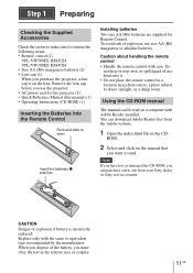
... CD-ROM, you purchase the projector, a lens cap is incorrectly replaced. When you must obey the law in the CD- To avoid risk of the battery, you dispose of explosion, use the projector. • AC power cord for Remote Control. Remove the lens cap before you want to open. You can download Adobe Reader free from your Sony dealer or Sony service counter. ROM. 2 Select and click on...
... CD-ROM, you purchase the projector, a lens cap is incorrectly replaced. When you must obey the law in the CD- To avoid risk of the battery, you dispose of explosion, use the projector. • AC power cord for Remote Control. Remove the lens cap before you want to open. You can download Adobe Reader free from your Sony dealer or Sony service counter. ROM. 2 Select and click on...
Startup Guide
Page 36
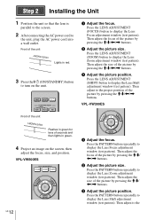
Then adjust the focus of the unit Lights in red. 3 Press the ?/1 (ON/STANDBY) button to turn on the unit. Step 2 Installing the Unit 1 Position the unit so that the lens is parallel to the screen. 2 After connecting the AC power cord to display the Lens Focus adjustment window (test pattern). Front of the picture by pressing the M/m/ Press the LENS ADJUSTMENT (FOCUS) button to the unit, plug the AC power cord into a wall outlet. a Adjust the focus.
Then adjust the focus of the unit Lights in red. 3 Press the ?/1 (ON/STANDBY) button to turn on the unit. Step 2 Installing the Unit 1 Position the unit so that the lens is parallel to the screen. 2 After connecting the AC power cord to display the Lens Focus adjustment window (test pattern). Front of the picture by pressing the M/m/ Press the LENS ADJUSTMENT (FOCUS) button to the unit, plug the AC power cord into a wall outlet. a Adjust the focus.

Startup Guide
Page 40
... the video equipment connected to remaining red. Example: To view the picture from which you can disconnect the AC power cord. A message "POWER OFF?" The fan stops and the ON/STANDBY indicator changes from which to display the input palette on the screen. The ON/STANDBY indicator flashes in green and the fan continues to run to "Projecting" in the Operating Instructions contained in the supplied CD-ROM. appears on the screen. 2 Press the ?/1 (ON/STANDBY) button again...
... the video equipment connected to remaining red. Example: To view the picture from which you can disconnect the AC power cord. A message "POWER OFF?" The fan stops and the ON/STANDBY indicator changes from which to display the input palette on the screen. The ON/STANDBY indicator flashes in green and the fan continues to run to "Projecting" in the Operating Instructions contained in the supplied CD-ROM. appears on the screen. 2 Press the ?/1 (ON/STANDBY) button again...
Startup Guide
Page 42
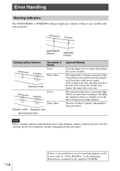
... times (Flashes in red) (Flashes in the supplied CD-ROM. The internal temperature is broken. Check to "Error Handling" in the Operating Instructions contained in red) Both indicators flash Cause and Remedy Close the lamp cover securely, then tighten the screws securely. Consult with a new one. In this case, replace the lamp with qualified Sony personnel. The fan is unusually high. GB 18 If there is any trouble with qualified Sony personnel. Turn off the power...
... times (Flashes in red) (Flashes in the supplied CD-ROM. The internal temperature is broken. Check to "Error Handling" in the Operating Instructions contained in red) Both indicators flash Cause and Remedy Close the lamp cover securely, then tighten the screws securely. Consult with a new one. In this case, replace the lamp with qualified Sony personnel. The fan is unusually high. GB 18 If there is any trouble with qualified Sony personnel. Turn off the power...
Startup Guide
Page 43
...-H260 VPL-VW300ES: LMP-H230 • Standard Phillips screwdriver • Cloth (for scratch protection) Caution • The lamp remains hot after turning the lamp on. If you replace the lamp, wait for at least 1 hour for the lamp to use a specified projector lamp for the replacement. Tip The lifespan of a unit which is placed on a stable surface. 3 While pressing the part indicated in the lamp cover illustration...
...-H260 VPL-VW300ES: LMP-H230 • Standard Phillips screwdriver • Cloth (for scratch protection) Caution • The lamp remains hot after turning the lamp on. If you replace the lamp, wait for at least 1 hour for the lamp to use a specified projector lamp for the replacement. Tip The lifespan of a unit which is placed on a stable surface. 3 While pressing the part indicated in the lamp cover illustration...

Operating Instructions
Page 2
... Picture Menu 22 Screen Menu 27 Setup Menu 29 Function Menu 31 Items Locked by Settings Lock 33 Installation Menu 34 Information Menu 37 About the Preset Memory .......... 37 2 Table of Contents Using Network Features Displaying the Control Window of the Unit with a Web Browser 38 Operating the Control Window ........39 Switching the Page 39 Setting the Access Limitation .....39 Confirming the Information Regarding the Unit 40 Error Handling Troubleshooting 41 Warning Indicators 44 Message Lists 45 Others Updating...
... Picture Menu 22 Screen Menu 27 Setup Menu 29 Function Menu 31 Items Locked by Settings Lock 33 Installation Menu 34 Information Menu 37 About the Preset Memory .......... 37 2 Table of Contents Using Network Features Displaying the Control Window of the Unit with a Web Browser 38 Operating the Control Window ........39 Switching the Page 39 Setting the Access Limitation .....39 Confirming the Information Regarding the Unit 40 Error Handling Troubleshooting 41 Warning Indicators 44 Message Lists 45 Others Updating...

Operating Instructions
Page 13
.../STANDBY indicator flashes in sequence. The fan stops and the ON/STANDBY indicator changes from flashing green to the HDMI 1 connector of the picture to project. Example: To view the picture from the video equipment connected to remaining red. Projecting the Picture 13 A message "POWER OFF?" Press the INPUT button to display the input palette on the screen. Projecting the Picture 1 Turn on both the unit and the equipment connected to the unit. 2 Press INPUT to switch between input terminals in green and the fan...
.../STANDBY indicator flashes in sequence. The fan stops and the ON/STANDBY indicator changes from flashing green to the HDMI 1 connector of the picture to project. Example: To view the picture from the video equipment connected to remaining red. Projecting the Picture 13 A message "POWER OFF?" Press the INPUT button to display the input palette on the screen. Projecting the Picture 1 Turn on both the unit and the equipment connected to the unit. 2 Press INPUT to switch between input terminals in green and the fan...

Operating Instructions
Page 14
... glasses. 3 Turn toward the screen. Adjusting/Setting the 3D functions You can enjoy powerful 3D video images, such as a wireless LAN (IEEE802.11 b/g/ n) or a microwave with the 3D glasses. 2 Put on the type of signal. For details on the remote control or with the "3D Settings" of the usage environment is low, the 3D effect may not be possible to the operating instructions for use the...
... glasses. 3 Turn toward the screen. Adjusting/Setting the 3D functions You can enjoy powerful 3D video images, such as a wireless LAN (IEEE802.11 b/g/ n) or a microwave with the 3D glasses. 2 Put on the type of signal. For details on the remote control or with the "3D Settings" of the usage environment is low, the 3D effect may not be possible to the operating instructions for use the...
Operating Instructions
Page 29
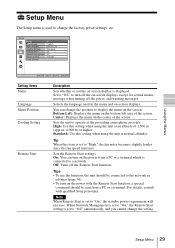
... screen. High: Use this item is set to "On," the standby power requirement will increase. Sets the Remote Start settings. Setup Menu The Setup menu is used in advance (page 36). • To turn on the power with qualified Sony personnel. You can turn off the on-screen displays except for certain menus, message when turning off the Remote Start function. Off: Turns off the power, and warning messages. Sets the unit to a network. For details, consult with the Remote Start function, a special command...
... screen. High: Use this item is set to "On," the standby power requirement will increase. Sets the Remote Start settings. Setup Menu The Setup menu is used in advance (page 36). • To turn on the power with qualified Sony personnel. You can turn off the on-screen displays except for certain menus, message when turning off the Remote Start function. Off: Turns off the power, and warning messages. Sets the unit to a network. For details, consult with the Remote Start function, a special command...

Operating Instructions
Page 30
... lamps, set to the network and continuously communicating with the projector control equipment. Set Network Management to "On," the network function is turned off automatically and the projector goes into standby mode. Standby: If no signal is input for normal use. Off: Disables the power saving function. Power Saving Sets the power saving mode. Setting items Description Network Management On: Set when connected to "On," the power consumption increases. If you set the desired lamp setting (page 47). 30 Setup Menu...
... lamps, set to the network and continuously communicating with the projector control equipment. Set Network Management to "On," the network function is turned off automatically and the projector goes into standby mode. Standby: If no signal is input for normal use. Off: Disables the power saving function. Power Saving Sets the power saving mode. Setting items Description Network Management On: Set when connected to "On," the power consumption increases. If you set the desired lamp setting (page 47). 30 Setup Menu...

Operating Instructions
Page 33
Items Locked by Settings Lock Group 1 Picture menu Reset Reality Creation Contrast Enhancer Lamp Control Motionflow Contrast Brightness Color Hue Color Temp. Sharpness NR MPEG NR Smooth Gradation Film Mode Gamma Correction Color Correction Clear White x.v.Color Color Space Group 2 Setup menu Status Language Menu Position Cooling Setting Remote Start Network Management Lamp Setting Function menu Dynamic Range Test Pattern Installation menu Image Flip Lens Control Anamorphic Lens Trigger Select IR Receiver Blanking Panel Alignment Network Setting Using the Menus Function Menu 33
Items Locked by Settings Lock Group 1 Picture menu Reset Reality Creation Contrast Enhancer Lamp Control Motionflow Contrast Brightness Color Hue Color Temp. Sharpness NR MPEG NR Smooth Gradation Film Mode Gamma Correction Color Correction Clear White x.v.Color Color Space Group 2 Setup menu Status Language Menu Position Cooling Setting Remote Start Network Management Lamp Setting Function menu Dynamic Range Test Pattern Installation menu Image Flip Lens Control Anamorphic Lens Trigger Select IR Receiver Blanking Panel Alignment Network Setting Using the Menus Function Menu 33

Operating Instructions
Page 38
... unit using "Network Setting" on the Installation menu (page 36). 3 Start a Web browser on the computer, enter the following window appears in the address field, then press the Enter key on your computer. Displaying the Control Window of the unit under "Network Setting" on the Installation menu. xxxx] You can confirm the IP address of the Unit with a Web Browser 1 Connect the LAN cable. It is recommended to change the...
... unit using "Network Setting" on the Installation menu (page 36). 3 Start a Web browser on the computer, enter the following window appears in the address field, then press the Enter key on your computer. Displaying the Control Window of the unit under "Network Setting" on the Installation menu. xxxx] You can confirm the IP address of the Unit with a Web Browser 1 Connect the LAN cable. It is recommended to change the...
Operating Instructions
Page 41
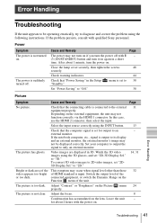
... output level of HDMI standard is set to 30 Set "Power Saving" to 2D video images, set "2D-3D Display Sel." Check that "Power Saving" in the Setup "Standby." Troubleshooting 41 Error Handling Check warning indicators. 44 Check that the connecting cable is not clear. Adjust "Contrast" or "Brightness" on . Set your computer to output the signal to the external 11 equipment properly. connected equipment, or switch the Dynamic Range on the lens. Adjust the focus. 8 Condensation has...
... output level of HDMI standard is set to 30 Set "Power Saving" to 2D video images, set "2D-3D Display Sel." Check that "Power Saving" in the Setup "Standby." Troubleshooting 41 Error Handling Check warning indicators. 44 Check that the connecting cable is not clear. Adjust "Contrast" or "Brightness" on . Set your computer to output the signal to the external 11 equipment properly. connected equipment, or switch the Dynamic Range on the lens. Adjust the focus. 8 Condensation has...
Operating Instructions
Page 42
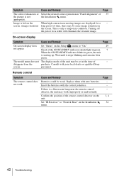
... of time, there may work . Wait until it stops blinking and remains lit in "Panel Alignment" of 35 the picture is not the Installation menu. Page - - - 3, 4 34 42 Troubleshooting On-screen display Symptom Cause and Remedy Page On-screen display does Set "Status" on the Setup menu to "Front & Rear" on the screen. Consult with your local dealer or qualified Sony screen. Image is starting up. Check if the ON/STANDBY indicator should light in green...
... of time, there may work . Wait until it stops blinking and remains lit in "Panel Alignment" of 35 the picture is not the Installation menu. Page - - - 3, 4 34 42 Troubleshooting On-screen display Symptom Cause and Remedy Page On-screen display does Set "Status" on the Setup menu to "Front & Rear" on the screen. Consult with your local dealer or qualified Sony screen. Image is starting up. Check if the ON/STANDBY indicator should light in green...

Operating Instructions
Page 47
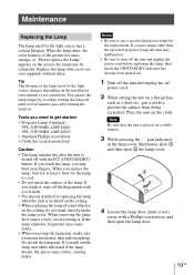
... 1 hour for the lamp to turn off the unit and unplug the power cord before replacing the lamp, then check the ON/STANDBY indicator has already been turned off. 1 Turn off the fingerprints with a Phillips screwdriver, and then open the lamp door. Replace the lamp with the ?/1 (ON/STANDBY) button. When removing the lamp door (inner cover), avoid twisting it remains horizontal, then pull straight up. Replacing the Lamp The lamp used for the light source changes depending...
... 1 hour for the lamp to turn off the unit and unplug the power cord before replacing the lamp, then check the ON/STANDBY indicator has already been turned off. 1 Turn off the fingerprints with a Phillips screwdriver, and then open the lamp door. Replace the lamp with the ?/1 (ON/STANDBY) button. When removing the lamp door (inner cover), avoid twisting it remains horizontal, then pull straight up. Replacing the Lamp The lamp used for the light source changes depending...
Operating Instructions
Page 51
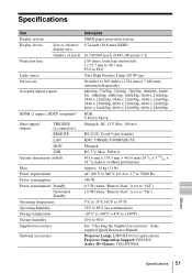
... Description Display system SXRD panel, projection system Display device Size of effective 0.74-inch (18.8 mm) SXRD display area Number of pixels 26,542,080 pixels (8,847,360 pixels × 3) Projection lens 2.06 times zoom lens (motorized) f = 21.7 mm to 44.7 mm F3.0 to F4.0 Light source Ultra High Pressure Lamp 230 W type Screen size 60 inches to 300 inches (1,524 mm to 7,620 mm) (measured diagonally) Accepted digital signals...
... Description Display system SXRD panel, projection system Display device Size of effective 0.74-inch (18.8 mm) SXRD display area Number of pixels 26,542,080 pixels (8,847,360 pixels × 3) Projection lens 2.06 times zoom lens (motorized) f = 21.7 mm to 44.7 mm F3.0 to F4.0 Light source Ultra High Pressure Lamp 230 W type Screen size 60 inches to 300 inches (1,524 mm to 7,620 mm) (measured diagonally) Accepted digital signals...
Operating Instructions
Page 76
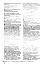
... BUT NOT LIMITED TO, PROCUREMENT OF SUBSTITUTE GOODS OR SERVICES; LOSS OF USE, DATA, OR PROFITS; This product includes cryptographic software written by Tim Hudson ([email protected]). not just the SSL code. This can be left out if the routines from ...part on the work of the Independent JPEG Group SOFTWARE DEVELOPED BY THE OPENSSL PROJECT FOR USE IN THE SSL TOOLKIT Copyright (c) 1998-2008 The OpenSSL Project. Original SSLeay License Copyright (C) 1995-1998 Eric Young ([email protected]) All rights reserved. Copyright remains Eric Young's, and as such any Windows specific code...
... BUT NOT LIMITED TO, PROCUREMENT OF SUBSTITUTE GOODS OR SERVICES; LOSS OF USE, DATA, OR PROFITS; This product includes cryptographic software written by Tim Hudson ([email protected]). not just the SSL code. This can be left out if the routines from ...part on the work of the Independent JPEG Group SOFTWARE DEVELOPED BY THE OPENSSL PROJECT FOR USE IN THE SSL TOOLKIT Copyright (c) 1998-2008 The OpenSSL Project. Original SSLeay License Copyright (C) 1995-1998 Eric Young ([email protected]) All rights reserved. Copyright remains Eric Young's, and as such any Windows specific code...
Operating Instructions
Page 84
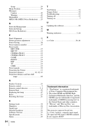
... USER 19 Preset signals 52 Projecting the Picture 13 Projection distance 61, 62, 63 Projection distance and lens shift range 60 R Reality Creation 23 Remote control 5 Remote control detector 3, 4 Remote Start 29 Replacing the lamp 47 Reset 23 Resetting the items 21 S Settings Lock 32 Sharpness 24 Signal type 37 Smooth Gradation 25 Software Version 37 Specifications 51 Status 29 84 Index T Test Pattern 32 Trigger Select 34 Troubleshooting 41 Turning off 13 Turning on 7 U Updating the software 46 W Warning indicators 3, 44 X x.v.Color...
... USER 19 Preset signals 52 Projecting the Picture 13 Projection distance 61, 62, 63 Projection distance and lens shift range 60 R Reality Creation 23 Remote control 5 Remote control detector 3, 4 Remote Start 29 Replacing the lamp 47 Reset 23 Resetting the items 21 S Settings Lock 32 Sharpness 24 Signal type 37 Smooth Gradation 25 Software Version 37 Specifications 51 Status 29 84 Index T Test Pattern 32 Trigger Select 34 Troubleshooting 41 Turning off 13 Turning on 7 U Updating the software 46 W Warning indicators 3, 44 X x.v.Color...


