
Operating Instructions
Page 3
... and found to comply with the limits for a Class B digital device, pursuant to Part 15 of FCC Rules. These limits are recyclable. The supplied interface cable must be determined by turning the equipment off and on a circuit different from that interference will not occur in accordance with the limits for help...
... and found to comply with the limits for a Class B digital device, pursuant to Part 15 of FCC Rules. These limits are recyclable. The supplied interface cable must be determined by turning the equipment off and on a circuit different from that interference will not occur in accordance with the limits for help...
Operating Instructions
Page 4
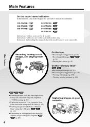
...8226;Capturing images on your computer from your camcorder on your computer Before you start reading this manual, camcorder-shape icons are used to capture images onto your computer (p. 208) 4 Capturing images on a "Memory Stick" using the USB cable (p. 185) •Converting an analog signal...Main Features •Viewing pictures recorded on a tape or live from your camcorder using the USB cable (p. 197) •Viewing images recorded on your computer - Instructions with no icons are for all models. CCD-TRV118 : CCD-TRV318 : CCD-TRV418 : DCR-TRV150 : DCR-TRV250 : DCR-TRV350 :...
...8226;Capturing images on your computer from your camcorder on your computer Before you start reading this manual, camcorder-shape icons are used to capture images onto your computer (p. 208) 4 Capturing images on a "Memory Stick" using the USB cable (p. 185) •Converting an analog signal...Main Features •Viewing pictures recorded on a tape or live from your camcorder using the USB cable (p. 197) •Viewing images recorded on your computer - Instructions with no icons are for all models. CCD-TRV118 : CCD-TRV318 : CCD-TRV418 : DCR-TRV150 : DCR-TRV250 : DCR-TRV350 :...
Operating Instructions
Page 7
... the "Memory Stick" on a "Memory Stick 156 Setting up a folder 160 - Introduction 182 Connecting your camcorder to a tape 170 Enlarging still images recorded on your camcorder on a "Memory Stick" - Insert Editing 123 "Memory Stick" Operations - MEMORY MIX 140 Recording moving picture...176 Deleting images - USB Streaming ......... 197 Viewing images recorded on a "Memory Stick" on your computer 202 Connecting your camcorder to your computer using the USB cable ......... 187 Viewing pictures recorded on a tape or live from a tape as a moving pictures on a "Memory Stick" ...
... the "Memory Stick" on a "Memory Stick 156 Setting up a folder 160 - Introduction 182 Connecting your camcorder to a tape 170 Enlarging still images recorded on your camcorder on a "Memory Stick" - Insert Editing 123 "Memory Stick" Operations - MEMORY MIX 140 Recording moving picture...176 Deleting images - USB Streaming ......... 197 Viewing images recorded on a "Memory Stick" on your computer 202 Connecting your camcorder to your computer using the USB cable ......... 187 Viewing pictures recorded on a tape or live from a tape as a moving pictures on a "Memory Stick" ...
Operating Instructions
Page 9
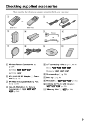
Checking supplied accessories Make sure that the following accessories are supplied with your camcorder. 1 2 or RMT-814 3 RMT-708 4 5 6 Stereo or Monaural 7 8 9 q; 1 Wireless Remote Commander (1) (p. 264) RMT-814: RMT-708: 2 AC-L15A/L15B ... (1) (p. 19) 3 NP-FM30 Rechargeable Battery Pack (1) (p. 18, 19) 4 Size AA (R6) battery for Remote Commander (2) (p. 264) 5 A/V connecting cable (1) (p. 51, 94, 95) Stereo: Monaural: 6 Shoulder strap (1) (p. 256) 7 Lens cap (1) (p. 30) 8 USB cable (1) (p. 182) 9 CD-ROM (SPVD-010 USB Driver) (1) (p. 189) 0 "Memory Stick" (1) (p. 240) 9
Checking supplied accessories Make sure that the following accessories are supplied with your camcorder. 1 2 or RMT-814 3 RMT-708 4 5 6 Stereo or Monaural 7 8 9 q; 1 Wireless Remote Commander (1) (p. 264) RMT-814: RMT-708: 2 AC-L15A/L15B ... (1) (p. 19) 3 NP-FM30 Rechargeable Battery Pack (1) (p. 18, 19) 4 Size AA (R6) battery for Remote Commander (2) (p. 264) 5 A/V connecting cable (1) (p. 51, 94, 95) Stereo: Monaural: 6 Shoulder strap (1) (p. 256) 7 Lens cap (1) (p. 30) 8 USB cable (1) (p. 182) 9 CD-ROM (SPVD-010 USB Driver) (1) (p. 189) 0 "Memory Stick" (1) (p. 240) 9
Operating Instructions
Page 16
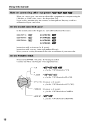
...the POWER switch Modes on the POWER switch vary depending on connecting other equipment When you connect your camcorder to other video equipment or a computer using the USB cable or i.LINK cable, observe the shape of the jack. Set the POWER switch to VCR. : e.g. Set the POWER...may be damaged and they may result in a malfunction of your camcorder. OFF (CHG) : Common to all models e.g. MEMORY : e.g. On the model name indication In this manual, camcorder-shape icons are for the indicated models only. CCD-TRV118 : CCD-TRV318 : CCD-TRV418 : DCR-TRV150 : DCR-TRV250 : DCR-...
...the POWER switch Modes on the POWER switch vary depending on connecting other equipment When you connect your camcorder to other video equipment or a computer using the USB cable or i.LINK cable, observe the shape of the jack. Set the POWER switch to VCR. : e.g. Set the POWER...may be damaged and they may result in a malfunction of your camcorder. OFF (CHG) : Common to all models e.g. MEMORY : e.g. On the model name indication In this manual, camcorder-shape icons are for the indicated models only. CCD-TRV118 : CCD-TRV318 : CCD-TRV418 : DCR-TRV150 : DCR-TRV250 : DCR-...
Operating Instructions
Page 51
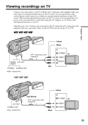
... with your TV. Connect your camcorder. Basics Viewing recordings on TV Connect your camcorder to your TV with the A/V connecting cable supplied with your camcorder to the TV using the AC Adaptor (p. 24). When monitoring playback pictures on the TV to watch playback pictures on the LCD screen. A/V connecting cable (supplied) AUDIO/ A/ V OUT VIDEO Red S VIDEO...
... with your TV. Connect your camcorder. Basics Viewing recordings on TV Connect your camcorder to your TV with the A/V connecting cable supplied with your camcorder to the TV using the AC Adaptor (p. 24). When monitoring playback pictures on the TV to watch playback pictures on the LCD screen. A/V connecting cable (supplied) AUDIO/ A/ V OUT VIDEO Red S VIDEO...
Operating Instructions
Page 52
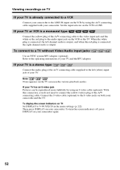
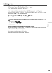
...input jacks Use an NTSC system RFU adaptor (optional). When the white plug is connected, the left (white) input jack of your camcorder and the TV. Connect the S video cable (optional) to the S video jacks on both your TV and the RFU adaptor. To display the screen indicators on TV Set ...DISPLAY to V-OUT/LCD in the various playback modes. Refer to the operating instructions of your TV. Note Noise appears on the TV screen...
...input jacks Use an NTSC system RFU adaptor (optional). When the white plug is connected, the left (white) input jack of your camcorder and the TV. Connect the S video cable (optional) to the S video jacks on both your TV and the RFU adaptor. To display the screen indicators on TV Set ...DISPLAY to V-OUT/LCD in the various playback modes. Refer to the operating instructions of your TV. Note Noise appears on the TV screen...

Operating Instructions
Page 60
...and the SteadyShot does not function: - 16:9WIDE to ON - 16:9WIDE to 16:9FULL Date or time indicator When you connect your camcorder to OFF in the menu settings. In the wide mode The SteadyShot does not work. In the wide mode You cannot operate the following ...functions: - OLD MOVIE (p. 65) - If you set the wide mode to other equipment by an A/V connecting cable. ID-2 system The ID-2 system sends a copyright protection signal with video signals. BOUNCE (p. 61) Connection for a TV Pictures recorded in the 16:9WIDE mode...
...and the SteadyShot does not function: - 16:9WIDE to ON - 16:9WIDE to 16:9FULL Date or time indicator When you connect your camcorder to OFF in the menu settings. In the wide mode The SteadyShot does not work. In the wide mode You cannot operate the following ...functions: - OLD MOVIE (p. 65) - If you set the wide mode to other equipment by an A/V connecting cable. ID-2 system The ID-2 system sends a copyright protection signal with video signals. BOUNCE (p. 61) Connection for a TV Pictures recorded in the 16:9WIDE mode...
Operating Instructions
Page 76
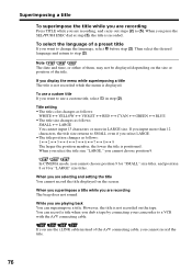
...menu is positioned. When you are playing back You can record a title when you dub a tape by connecting your camcorder to a VCR with the A/V connecting cable. If you use the i.LINK cable instead of the title. You can superimpose a title. Note The date and time, or either of them, may not... be displayed depending on the size or position of the A/V connecting cable, you cannot record the title. 76 Superimposing a title To superimpose the title while you are recording Press TITLE while you are recording The beep does...
...menu is positioned. When you are playing back You can record a title when you dub a tape by connecting your camcorder to a VCR with the A/V connecting cable. If you use the i.LINK cable instead of the title. You can superimpose a title. Note The date and time, or either of them, may not... be displayed depending on the size or position of the A/V connecting cable, you cannot record the title. 76 Superimposing a title To superimpose the title while you are recording Press TITLE while you are recording The beep does...
Operating Instructions
Page 94
... recorded tape on the VCR. Editing - Before operation • Set DISPLAY to LCD in the menu settings. (The default setting is LCD.) • Press the following buttons to LINE. Connect the A/V connecting cable to your camcorder using your camcorder. (5) Start recording on your camcorder as a player. SEARCH MODE on the VCR connected to the AUDIO/VIDEO...
... recorded tape on the VCR. Editing - Before operation • Set DISPLAY to LCD in the menu settings. (The default setting is LCD.) • Press the following buttons to LINE. Connect the A/V connecting cable to your camcorder using your camcorder. (5) Start recording on your camcorder as a player. SEARCH MODE on the VCR connected to the AUDIO/VIDEO...

Operating Instructions
Page 95
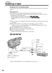
... on VCRs that support the following systems: 8 mm , Hi8 , Digital8 , VHS , S-VHS , VHSC , S-VHSC , Betamax , ED Betamax , mini DV , DV , or MICRO MV . If your camcorder and the VCR. To prevent deterioration of the A/V connecting cable. If your VCR is a stereo type Connect the audio... plug of the A/V connecting cable to connect the yellow (video) plug of pictures when dubbing Set EDIT to ON...
... on VCRs that support the following systems: 8 mm , Hi8 , Digital8 , VHS , S-VHS , VHSC , S-VHSC , Betamax , ED Betamax , mini DV , DV , or MICRO MV . If your camcorder and the VCR. To prevent deterioration of the A/V connecting cable. If your VCR is a stereo type Connect the audio... plug of the A/V connecting cable to connect the yellow (video) plug of pictures when dubbing Set EDIT to ON...
Operating Instructions
Page 96
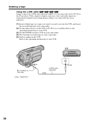
With a digital-to record over) into the VCR, and insert the recorded tape into your camcorder. (5) Start recording on the VCR. Dubbing a tape Using the i.LINK cable Simply connect the i.LINK cable (optional) to DV on your VCR. Refer to the operating instructions of your VCR. (3) Set the POWER switch to VCR... on your camcorder. (4) Play back the recorded tape on your camcorder. (2) Set the input selector on the VCR to DV IN on this side. : Signal flow i.LINK cable (optional) DV DV IN 96 VCR DV is available. Refer to the ...
With a digital-to record over) into the VCR, and insert the recorded tape into your camcorder. (5) Start recording on the VCR. Dubbing a tape Using the i.LINK cable Simply connect the i.LINK cable (optional) to DV on your VCR. Refer to the operating instructions of your VCR. (3) Set the POWER switch to VCR... on your camcorder. (4) Play back the recorded tape on your camcorder. (2) Set the input selector on the VCR to DV IN on this side. : Signal flow i.LINK cable (optional) DV DV IN 96 VCR DV is available. Refer to the ...
Operating Instructions
Page 97
You can connect one VCR only using the i.LINK cable See page 244 for more information about i.LINK. Tape PB ZOOM - Pictures processed by the following functions cannot be output through the DV jack: - Digital signals are recorded in the Hi8 /standard 8 mm system The picture may jitter.... Picture effect If you play back the picture using other video equipment, the picture may fluctuate. Note on both your camcorder and the VCR. This is not a malfunction. Also, when...
You can connect one VCR only using the i.LINK cable See page 244 for more information about i.LINK. Tape PB ZOOM - Pictures processed by the following functions cannot be output through the DV jack: - Digital signals are recorded in the Hi8 /standard 8 mm system The picture may jitter.... Picture effect If you play back the picture using other video equipment, the picture may fluctuate. Note on both your camcorder and the VCR. This is not a malfunction. Also, when...
Operating Instructions
Page 98
...easily by using the same VCR again, you dub using an S video cable (optional). Connect an S video cable (optional) to connect the yellow (video) plug of eight preset titles and two custom titles stored in your camcorder as illustrated in a title, you do not need to 102) Step 3... that support the following systems: 8 mm , Hi8 , Digital8 , VHS , S-VHS , VHSC , S-VHSC , Betamax , ED Betamax , mini DV , DV , or MICRO MV . You can skip Step 3 (p. 103). Step 1: Connecting the VCR Connect the devices as instructed in "Making your camcorder (p. 99 to put in page 95. With ...
...easily by using the same VCR again, you dub using an S video cable (optional). Connect an S video cable (optional) to connect the yellow (video) plug of eight preset titles and two custom titles stored in your camcorder as illustrated in a title, you do not need to 102) Step 3... that support the following systems: 8 mm , Hi8 , Digital8 , VHS , S-VHS , VHSC , S-VHSC , Betamax , ED Betamax , mini DV , DV , or MICRO MV . You can skip Step 3 (p. 103). Step 1: Connecting the VCR Connect the devices as instructed in "Making your camcorder (p. 99 to put in page 95. With ...
Operating Instructions
Page 99
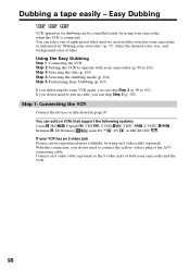
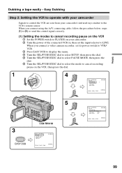
.../PUSH EXEC dial to select the mode to cancel recording pause on , then set the input selector to control the VCR are sent from your camcorder. 2 Turn the power of the connected VCR on the VCR, then press the dial. 1 PL POWER RA CAME AYER OFF(CHG) 4 EASY DUBBING SETUP I...DUBBING 0:00:00 SETUP I R SETUP PAUSE MODE PAUSE I R TEST REC RETURN PB [ EASY DUB ] : END NORMAL 99 When you connect using the A/V connecting cable, follow the procedure below, steps (1) to (4), to send the control signal correctly. (1) Setting the modes to cancel recording pause on the VCR 1 Set the POWER...
.../PUSH EXEC dial to select the mode to cancel recording pause on , then set the input selector to control the VCR are sent from your camcorder. 2 Turn the power of the connected VCR on the VCR, then press the dial. 1 PL POWER RA CAME AYER OFF(CHG) 4 EASY DUBBING SETUP I...DUBBING 0:00:00 SETUP I R SETUP PAUSE MODE PAUSE I R TEST REC RETURN PB [ EASY DUB ] : END NORMAL 99 When you connect using the A/V connecting cable, follow the procedure below, steps (1) to (4), to send the control signal correctly. (1) Setting the modes to cancel recording pause on the VCR 1 Set the POWER...
Operating Instructions
Page 102
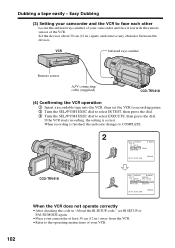
When recording is correct. Easy Dubbing (3) Setting your camcorder and the VCR to the operating instructions of your camcorder and face it towards the remote sensor of your VCR. If the VCR starts recording, the setting is finished, the indicator changes to COMPLETE....; Refer to face each other Locate the infrared rays emitter of the VCR. Dubbing a tape easily - VCR Infrared rays emitter 102 Remote sensor A/V connecting cable (supplied) CCD-TRV418 (4) Confirming the VCR operation 1 Insert a recordable tape into the VCR, then set IR SETUP or PAUSE MODE again. • Place ...
When recording is correct. Easy Dubbing (3) Setting your camcorder and the VCR to the operating instructions of your camcorder and face it towards the remote sensor of your VCR. If the VCR starts recording, the setting is finished, the indicator changes to COMPLETE....; Refer to face each other Locate the infrared rays emitter of the VCR. Dubbing a tape easily - VCR Infrared rays emitter 102 Remote sensor A/V connecting cable (supplied) CCD-TRV418 (4) Confirming the VCR operation 1 Insert a recordable tape into the VCR, then set IR SETUP or PAUSE MODE again. • Place ...
Operating Instructions
Page 106
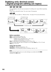
with tapes recorded in the Hi8 / standard 8 mm system. 106 Digital program editing (on a "Memory Stick." Scenes can dub on tapes) You can skip Step 2 (p. 107 to 112) and Step 3 (p. 113 to 20 programs. Your camcorder can be selected by frame. You can set up to 114...program (p. 115) Operation 2 Performing the program (Dubbing a tape) (p. 118) Note Digital program editing does not work with the i.LINK cable (p. 111 to 110) - with the A/V connecting cable (p. 107 to 112) Step 3 Adjusting the synchronization of the VCR (p. 113) When you dub using the same VCR again, you can...
with tapes recorded in the Hi8 / standard 8 mm system. 106 Digital program editing (on a "Memory Stick." Scenes can dub on tapes) You can skip Step 2 (p. 107 to 112) and Step 3 (p. 113 to 20 programs. Your camcorder can be selected by frame. You can set up to 114...program (p. 115) Operation 2 Performing the program (Dubbing a tape) (p. 118) Note Digital program editing does not work with the i.LINK cable (p. 111 to 110) - with the A/V connecting cable (p. 107 to 112) Step 3 Adjusting the synchronization of the VCR (p. 113) When you dub using the same VCR again, you can...
Operating Instructions
Page 107
...format for operation with the A/V connecting cable To edit using the A/V connecting cable, follow the procedure below, steps (1) to (4), to send the control signal correctly. (1) Set the IR SETUP code 1 Set the POWER switch to VCR on your camcorder. 2 Turn the power of your camcorder to send the control signal by ... and audio signals are transmitted in page 94. Check the code in VIDEO EDIT, then press the dial. When you connect using the i.LINK cable With a digital-to select IR SETUP code number of the connected VCR on page 96. Digital program editing (on the VCR. Step 2: Setting...
...format for operation with the A/V connecting cable To edit using the A/V connecting cable, follow the procedure below, steps (1) to (4), to send the control signal correctly. (1) Set the IR SETUP code 1 Set the POWER switch to VCR on your camcorder. 2 Turn the power of your camcorder to send the control signal by ... and audio signals are transmitted in page 94. Check the code in VIDEO EDIT, then press the dial. When you connect using the i.LINK cable With a digital-to select IR SETUP code number of the connected VCR on page 96. Digital program editing (on the VCR. Step 2: Setting...
Operating Instructions
Page 109
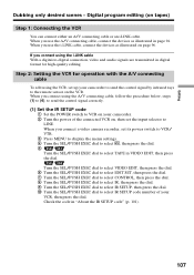
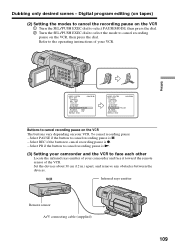
VCR Infrared rays emitter Remote sensor A/V connecting cable (supplied) 109 Editing VIDEO EDIT 0:08:55:06 EDIT SET CONTROL ADJ TEST ... of the VCR. Select PAUSE if the button to face each other Locate the infrared rays emitter of your camcorder and face it toward the remote sensor of your VCR. Set the devices about 30 cm (12 in.) ...The buttons vary depending on your VCR. Select PB if the button to cancel recording pause is N. (3) Setting your camcorder and the VCR to cancel recording pause is z. - Dubbing only desired scenes - Select REC if the button to ...
VCR Infrared rays emitter Remote sensor A/V connecting cable (supplied) 109 Editing VIDEO EDIT 0:08:55:06 EDIT SET CONTROL ADJ TEST ... of the VCR. Select PAUSE if the button to face each other Locate the infrared rays emitter of your camcorder and face it toward the remote sensor of your VCR. Set the devices about 30 cm (12 in.) ...The buttons vary depending on your VCR. Select PB if the button to cancel recording pause is N. (3) Setting your camcorder and the VCR to cancel recording pause is z. - Dubbing only desired scenes - Select REC if the button to ...
Operating Instructions
Page 111
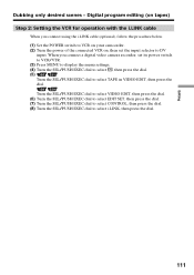
..., then press the dial. (8) Turn the SEL/PUSH EXEC dial to DV input. When you connect using the i.LINK cable (optional), follow the procedure below. (1) Set the POWER switch to VCR on your camcorder. (2) Turn the power of the connected VCR on tapes) Step 2: Setting the VCR for operation with the i.LINK...
..., then press the dial. (8) Turn the SEL/PUSH EXEC dial to DV input. When you connect using the i.LINK cable (optional), follow the procedure below. (1) Set the POWER switch to VCR on your camcorder. (2) Turn the power of the connected VCR on tapes) Step 2: Setting the VCR for operation with the i.LINK...


