Operating Instructions
Page 1
Record the serial number in the space provided below. Refer to them whenever you call upon your Sony dealer regarding this product. STR-DG800 ©2006 Sony Corporation Model No. Serial No. 2-667-346-12 (1) Multi Channel AV Receiver Operating Instructions Owner's Record The model and serial numbers are located on the rear of the unit.
Record the serial number in the space provided below. Refer to them whenever you call upon your Sony dealer regarding this product. STR-DG800 ©2006 Sony Corporation Model No. Serial No. 2-667-346-12 (1) Multi Channel AV Receiver Operating Instructions Owner's Record The model and serial numbers are located on the rear of the unit.
Operating Instructions
Page 2
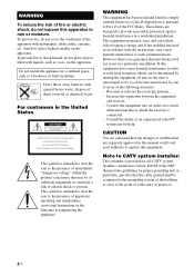
...from that any changes or modification not expressly approved in this equipment does cause harmful interference to radio or television reception, which the receiver is encouraged to try to the presence of cable entry as vases, on the apparatus. However, there is provided to call CATV ... to constitute a risk of electric shock to Part 15 of the following measures: - Reorient or relocate the receiving antenna. - Increase the separation between the equipment and receiver. - Note to CATV system installer: This reminder is no guarantee that the cable ground shall be connected to...
...from that any changes or modification not expressly approved in this equipment does cause harmful interference to radio or television reception, which the receiver is encouraged to try to the presence of cable entry as vases, on the apparatus. However, there is provided to call CATV ... to constitute a risk of electric shock to Part 15 of the following measures: - Reorient or relocate the receiving antenna. - Increase the separation between the equipment and receiver. - Note to CATV system installer: This reminder is no guarantee that the cable ground shall be connected to...
Operating Instructions
Page 3
..., the HDMI logo and High-Definition Multimedia Interface are clearly indicated in the text, for model STR-DG800. Area code DIGITAL OPTICAL VIDEO 1 IN TV/SAT IN MD/ TAPE IN MD/ TAPE OUT...L L L R IN IN PHONO SA-CD/CD R OUT IN MD/TAPE R R SURR FRONT SURROUND BACK MULTI CH IN Any differences in operation, according to the area code, are trademarks or registered trademarks of XM Satellite Radio...remote. XM is shown on the remote. About area codes The area code of the receiver you purchased is a registered trademark of HDMI Licensing LLC. Check your model number by ...
..., the HDMI logo and High-Definition Multimedia Interface are clearly indicated in the text, for model STR-DG800. Area code DIGITAL OPTICAL VIDEO 1 IN TV/SAT IN MD/ TAPE IN MD/ TAPE OUT...L L L R IN IN PHONO SA-CD/CD R OUT IN MD/TAPE R R SURR FRONT SURROUND BACK MULTI CH IN Any differences in operation, according to the area code, are trademarks or registered trademarks of XM Satellite Radio...remote. XM is shown on the remote. About area codes The area code of the receiver you purchased is a registered trademark of HDMI Licensing LLC. Check your model number by ...
Operating Instructions
Page 4
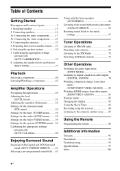
... Connecting speakers 16 3a: Connecting the audio components.........17 3b: Connecting the video components ........23 4: Connecting the antennas 32 5: Preparing the receiver and the remote .....33 6: Selecting the speaker system 35 7: Calibrating the appropriate settings automatically (AUTO CALIBRATION 35 8: Adjusting the speaker levels...inputs (HDMI VIDEO ASSIGN 81 Naming inputs 82 Changing the display 83 Using the Sleep Timer 83 Recording using the receiver 84 Listening to the sound in another zone ....... 85 Using the Remote Programming the remote 86 Additional Information Glossary...
... Connecting speakers 16 3a: Connecting the audio components.........17 3b: Connecting the video components ........23 4: Connecting the antennas 32 5: Preparing the receiver and the remote .....33 6: Selecting the speaker system 35 7: Calibrating the appropriate settings automatically (AUTO CALIBRATION 35 8: Adjusting the speaker levels...inputs (HDMI VIDEO ASSIGN 81 Naming inputs 82 Changing the display 83 Using the Sleep Timer 83 Recording using the receiver 84 Listening to the sound in another zone ....... 85 Using the Remote Programming the remote 86 Additional Information Glossary...
Operating Instructions
Page 5
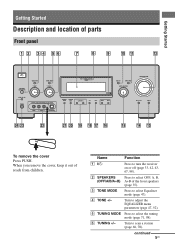
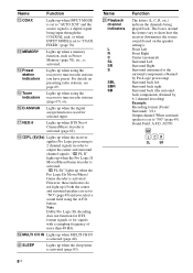
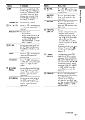
... Front panel 1 2 34 56 7 8 9 q; Name Function A ?/1 Press to select the tuning mode (page 71, 98). E TUNING MODE Press to turn the receiver on or off (page 33, 42, 43, 67, 98). F TUNING +/- Turn to select OFF, A, B, (OFF/A/B/A+B) A+B of the front speakers (page 35)....(page 68, 70). TUNING + AUTO CAL MIC PHONES VIDEO 3 IN/PORTABLE AV IN VIDEO L AUDIO R DIGITAL(OPT) MULTI CHANNEL DECODING DISPLAY INPUT MODE INPUT SELECTOR MASTER VOLUME MEMORY/ CATEGORY ENTER MODE - MOVIE MUSIC MULTI CH IN DIRECT wf wd ws wa w; Turn to select Equalizer mode (page...
... Front panel 1 2 34 56 7 8 9 q; Name Function A ?/1 Press to select the tuning mode (page 71, 98). E TUNING MODE Press to turn the receiver on or off (page 33, 42, 43, 67, 98). F TUNING +/- Turn to select OFF, A, B, (OFF/A/B/A+B) A+B of the front speakers (page 35)....(page 68, 70). TUNING + AUTO CAL MIC PHONES VIDEO 3 IN/PORTABLE AV IN VIDEO L AUDIO R DIGITAL(OPT) MULTI CHANNEL DECODING DISPLAY INPUT MODE INPUT SELECTOR MASTER VOLUME MEMORY/ CATEGORY ENTER MODE - MOVIE MUSIC MULTI CH IN DIRECT wf wd ws wa w; Turn to select Equalizer mode (page...
Operating Instructions
Page 6
... information displayed on the display (page 82). Name Function S CATEGORY +/- H MULTI CHANNEL DECODING lamp Lights up when multi channel audio is decoded (page 43). P MOVIE, MUSIC Press to adjust the volume...the settings (page 33). Q A.F.D. U MEMORY/ ENTER Press to a headphone (page 94). I Remote sensor Receives signals from the components connected to playback (page 40, 42, 43, 66, 68, 71, 78, 82...digital and analog jacks (page 78). V VIDEO 3 IN/ To connect a camcorder or PORTABLE AV video game (page 29, 40). K INPUT MODE Press to select the input mode when ...
... information displayed on the display (page 82). Name Function S CATEGORY +/- H MULTI CHANNEL DECODING lamp Lights up when multi channel audio is decoded (page 43). P MOVIE, MUSIC Press to adjust the volume...the settings (page 33). Q A.F.D. U MEMORY/ ENTER Press to a headphone (page 94). I Remote sensor Receives signals from the components connected to playback (page 40, 42, 43, 66, 68, 71, 78, 82...digital and analog jacks (page 78). V VIDEO 3 IN/ To connect a camcorder or PORTABLE AV video game (page 29, 40). K INPUT MODE Press to select the input mode when ...
Operating Instructions
Page 7
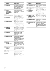
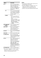
..." and the source signal is not set to "ONE CAT". Lights up when the receiver is selected (page 66). Lights up when the disc being played back contains an LFE (Low Frequency Effect) channel and the LFE channel signal is actually being input through the OPTICAL jack, or when INPUT MODE is connected... indicators do not light up when dynamic range compression is activated (page 47). qa qs qd SP.A SP.B A.DIRECT HDMI EQ D.RANGE SW LFE SLEEP MULTI CH IN ;PL IIx LCR SL S SR w;
..." and the source signal is not set to "ONE CAT". Lights up when the receiver is selected (page 66). Lights up when the disc being played back contains an LFE (Low Frequency Effect) channel and the LFE channel signal is actually being input through the OPTICAL jack, or when INPUT MODE is connected... indicators do not light up when dynamic range compression is activated (page 47). qa qs qd SP.A SP.B A.DIRECT HDMI EQ D.RANGE SW LFE SLEEP MULTI CH IN ;PL IIx LCR SL S SR w;
Operating Instructions
Page 8
..., or when INPUT MODE is selected (page 40). M MEMORY Lights up when MULTI CH IN is set to "NO" (page 49) and you have preset. O Tuner indicators Lights up when the receiver applies Pro Logic processing to 2 channel signals in order to "COAX FIXED" (page 78). PL IIx" lights up... when the Pro Logic II Movie/Music/Game decoder is set to output the center and surround channel signals. "; AUTO SW LCR SL SR ...
..., or when INPUT MODE is selected (page 40). M MEMORY Lights up when MULTI CH IN is set to "NO" (page 49) and you have preset. O Tuner indicators Lights up when the receiver applies Pro Logic processing to 2 channel signals in order to "COAX FIXED" (page 78). PL IIx" lights up... when the Pro Logic II Movie/Music/Game decoder is set to output the center and surround channel signals. "; AUTO SW LCR SL SR ...

Operating Instructions
Page 9
... Super Audio CD player or DVD player which has an analog audio jack for 7.1 channel sound (page 20). White (L) Red (R) MULTI CHANNEL INPUT jack Black Connects to the AM loop antenna supplied with this receiver (page 32). R FRONT A AC OUTLET A DIGITAL INPUT/OUTPUT section OPTICAL Connects ...B ANTENNA section FM ANTENNA AM ANTENNA XM Connects to the XM connect-andplay antenna (not supplied with this receiver) (page 72). Connects to the FM wire antenna supplied with this receiver (page 32). R SURROUND L + - S-VIDEO IN/ OUT jack* continued 9US C AUDIO INPUT/OUTPUT ...
... Super Audio CD player or DVD player which has an analog audio jack for 7.1 channel sound (page 20). White (L) Red (R) MULTI CHANNEL INPUT jack Black Connects to the AM loop antenna supplied with this receiver (page 32). R FRONT A AC OUTLET A DIGITAL INPUT/OUTPUT section OPTICAL Connects ...B ANTENNA section FM ANTENNA AM ANTENNA XM Connects to the XM connect-andplay antenna (not supplied with this receiver) (page 72). Connects to the FM wire antenna supplied with this receiver (page 32). R SURROUND L + - S-VIDEO IN/ OUT jack* continued 9US C AUDIO INPUT/OUTPUT ...
Operating Instructions
Page 10
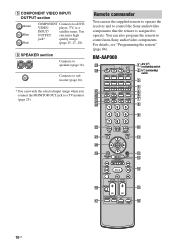
... MENU AMP qd - Remote commander You can enjoy high jack* quality image (page 25, 27, 28). TUNING AUTO CAL wf wd 123 1 AV ?/1 (on/standby) switch 2 ?/1 (on/standby) switch 3 4 5 6 7 8 456 9 789 ws - /- - CLEAR 0/10 ... DISPLAY TOOLS wa qa V w; RM-AAP008 wl TV RM SET UP AV ?/1 ?/1 wk SYSTEM STANDBY VIDEO 1 VIDEO 2 VIDEO 3 DVD TV/SAT MD/TAPE SA-CD/CD TUNER PHONO MULTI CH SOURCE 2ND ZONE wj wh 2CH A.F.D. m H TUNING + M ...can use the supplied remote to operate the receiver and to control the Sony audio/video components that the remote is assigned to control non...
... MENU AMP qd - Remote commander You can enjoy high jack* quality image (page 25, 27, 28). TUNING AUTO CAL wf wd 123 1 AV ?/1 (on/standby) switch 2 ?/1 (on/standby) switch 3 4 5 6 7 8 456 9 789 ws - /- - CLEAR 0/10 ... DISPLAY TOOLS wa qa V w; RM-AAP008 wl TV RM SET UP AV ?/1 ?/1 wk SYSTEM STANDBY VIDEO 1 VIDEO 2 VIDEO 3 DVD TV/SAT MD/TAPE SA-CD/CD TUNER PHONO MULTI CH SOURCE 2ND ZONE wj wh 2CH A.F.D. m H TUNING + M ...can use the supplied remote to operate the receiver and to control the Sony audio/video components that the remote is assigned to control non...
Operating Instructions
Page 11
... (SYSTEM STANDBY). When you press the input buttons (C). Press to select the current input for the main receiver. Press to control non-Sony components by changing the code. Button Assigned Sony component VIDEO 1 VCR (VTR mode 3) VIDEO 2 VCR (VTR mode 2) VIDEO 3 VCR (VTR mode... remote to enter direct tuning mode. For details see "Programming the remote" (page 86). Press to control Sony components as follows. Name Function C Input buttons Press one of the AV ?/1 switch changes automatically each time you press any of the remote. D 2ND ZONE E SOURCE F MOVIE...
... (SYSTEM STANDBY). When you press the input buttons (C). Press to select the current input for the main receiver. Press to control non-Sony components by changing the code. Button Assigned Sony component VIDEO 1 VCR (VTR mode 3) VIDEO 2 VCR (VTR mode 2) VIDEO 3 VCR (VTR mode... remote to enter direct tuning mode. For details see "Programming the remote" (page 86). Press to control Sony components as follows. Name Function C Input buttons Press one of the AV ?/1 switch changes automatically each time you press any of the remote. D 2ND ZONE E SOURCE F MOVIE...
Operating Instructions
Page 12
... tracks in recording standby.) 12US Press to display the menus of Sony TV, press TV (wk), and then press MENU. Press 0/10 to - select channel numbers of the VCR, CD player, VCD player, LD player,... the value after selecting a channel, disc or track using the numeric buttons. L AMP Press AMP to light up the button, then press MENU (M) to start playback of the receiver. Press to display the menu.../ backward direction of the CD player, VCD player, DVD player, MD deck or LD player (multi-disc changer only). Press to pause playback or recording of the VCR, DVD player, DVD/VIDEO ...
... tracks in recording standby.) 12US Press to display the menus of Sony TV, press TV (wk), and then press MENU. Press 0/10 to - select channel numbers of the VCR, CD player, VCD player, LD player,... the value after selecting a channel, disc or track using the numeric buttons. L AMP Press AMP to light up the button, then press MENU (M) to start playback of the receiver. Press to display the menu.../ backward direction of the CD player, VCD player, DVD player, MD deck or LD player (multi-disc changer only). Press to pause playback or recording of the VCR, DVD player, DVD/VIDEO ...
Operating Instructions
Page 13
.... - Press TV (wk), and then press TV CH +/- Press to display the DVD title of Sony TV, press TV (wk), and then press RETURN/ EXIT O. return to enter the selection. To return..., DVD/ VIDEO COMBO, or DVD/ HDD COMBO. TUNING +/- O TV CH +a)/- to - preset stations. - preset channels of the VCR, CD player, VCD player, LD player, DVD player, MD deck, DAT deck, tape deck, Blu-ray... recorder, PSX, DVD/VIDEO COMBO, or DVD/HDD COMBO. P F1, F2 Press to select the media (for receiver operation, DVD TOP MENU qj or DVD MENU qj, press the control button V, v, B or b to perform ...
.... - Press TV (wk), and then press TV CH +/- Press to display the DVD title of Sony TV, press TV (wk), and then press RETURN/ EXIT O. return to enter the selection. To return..., DVD/ VIDEO COMBO, or DVD/ HDD COMBO. TUNING +/- O TV CH +a)/- to - preset stations. - preset channels of the VCR, CD player, VCD player, LD player, DVD player, MD deck, DAT deck, tape deck, Blu-ray... recorder, PSX, DVD/VIDEO COMBO, or DVD/HDD COMBO. P F1, F2 Press to select the media (for receiver operation, DVD TOP MENU qj or DVD MENU qj, press the control button V, v, B or b to perform ...
Operating Instructions
Page 14
...radio. Press to select A.F.D. Press to activate the Sleep Timer function and the duration which the receiver turns off automatically. Use the tactile dots as an example only. Press to activate the buttons...MENU (qd), RETURN/EXIT O (ql), and DISPLAY (wa) buttons to select the category mode for Sony TVs only. To select the channel mode of the VCR, satellite tuner, CD player or MD deck, tape deck, TV, Blu-ray...track numbers over 10 of the TV, press TV (wk) and then press -/--. >10 Press to MULTI CH IN jacks (page 40). wk TV Press to set-up the button. wl RM SET UP Press...
...radio. Press to select A.F.D. Press to activate the Sleep Timer function and the duration which the receiver turns off automatically. Use the tactile dots as an example only. Press to activate the buttons...MENU (qd), RETURN/EXIT O (ql), and DISPLAY (wa) buttons to select the category mode for Sony TVs only. To select the channel mode of the VCR, satellite tuner, CD player or MD deck, tape deck, TV, Blu-ray...track numbers over 10 of the TV, press TV (wk) and then press -/--. >10 Press to MULTI CH IN jacks (page 40). wk TV Press to set-up the button. wl RM SET UP Press...
Operating Instructions
Page 15
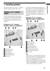
...receiver allows you to this receiver. 15US Example of a 7.1 channel speaker system configuration AFront speaker (L) BFront speaker (R) CCenter speaker DSurround speaker (L) ESurround speaker (R) HSub woofer AFront speaker (L) BFront speaker (R) CCenter speaker DSurround speaker (L) ESurround speaker (R) FSurround back speaker (L) GSurround back speaker (R) HSub woofer Tips • When you connect a 6.1 channel... reproduction of that amplifier. Enjoying a 5.1/7.1 channel system To fully enjoy theater-like multi channel surround sound requires five speakers (two front speakers, a ...
...receiver allows you to this receiver. 15US Example of a 7.1 channel speaker system configuration AFront speaker (L) BFront speaker (R) CCenter speaker DSurround speaker (L) ESurround speaker (R) HSub woofer AFront speaker (L) BFront speaker (R) CCenter speaker DSurround speaker (L) ESurround speaker (R) FSurround back speaker (L) GSurround back speaker (R) HSub woofer Tips • When you connect a 6.1 channel... reproduction of that amplifier. Enjoying a 5.1/7.1 channel system To fully enjoy theater-like multi channel surround sound requires five speakers (two front speakers, a ...
Operating Instructions
Page 17
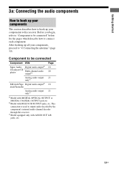
... your components to this receiver. b)Model with AUDIO OUT L/R jacks, etc. 17US Component to connect each component. Before you begin, refer to "Component to be connected" below for the pages which describe how to be connected Component With Super Audio Digital audio outputa) CD player/CD player Multi-channel audio outputb) Page 18...
... your components to this receiver. b)Model with AUDIO OUT L/R jacks, etc. 17US Component to connect each component. Before you begin, refer to "Component to be connected" below for the pages which describe how to be connected Component With Super Audio Digital audio outputa) CD player/CD player Multi-channel audio outputb) Page 18...
Operating Instructions
Page 19
... the operating instructions supplied with 32 kHz, 44.1 kHz, 48 kHz, and 96 kHz sampling frequencies. 19US When you make digital connections and to the MULTI CH IN or SA-CD/CD IN jack. To make digital recordings, make only analog connections. Use the analog jack for recording in this...
... the operating instructions supplied with 32 kHz, 44.1 kHz, 48 kHz, and 96 kHz sampling frequencies. 19US When you make digital connections and to the MULTI CH IN or SA-CD/CD IN jack. To make digital recordings, make only analog connections. Use the analog jack for recording in this...
Operating Instructions
Page 20
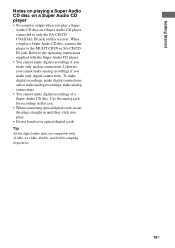
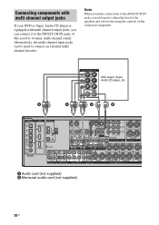
...- Note When you make connections to the MULTI CH IN jacks, you can be used to adjust the level of this receiver to enjoy multi channel sound. DVD player, Super Audio CD player, etc. Connecting components with multi channel output jacks If your DVD or Super Audio... CD player is equipped with multi channel output jacks, you will need to connect an external multi channel decoder. R SURROUND ...
...- Note When you make connections to the MULTI CH IN jacks, you can be used to adjust the level of this receiver to enjoy multi channel sound. DVD player, Super Audio CD player, etc. Connecting components with multi channel output jacks If your DVD or Super Audio... CD player is equipped with multi channel output jacks, you will need to connect an external multi channel decoder. R SURROUND ...
Operating Instructions
Page 22
To prevent this receiver. This is not a malfunction and will depend on the front panel of this , you can reduce the input level sound of this receiver. For details, refer to operating instructions supplied with the Portable Audio. • Distortion may occur when listening to a component connected to the VIDEO 3 IN/ PORTABLE AV IN (AUDIO) jack of the other components. 22US Notes • To listen to the portable audio source sound, connect the audio output jack of portable audio to the VIDEO 3 IN/ PORTABLE AV IN (AUDIO) jack on the component connected.
To prevent this receiver. This is not a malfunction and will depend on the front panel of this , you can reduce the input level sound of this receiver. For details, refer to operating instructions supplied with the Portable Audio. • Distortion may occur when listening to a component connected to the VIDEO 3 IN/ PORTABLE AV IN (AUDIO) jack of the other components. 22US Notes • To listen to the portable audio source sound, connect the audio output jack of portable audio to the VIDEO 3 IN/ PORTABLE AV IN (AUDIO) jack on the component connected.
Operating Instructions
Page 23
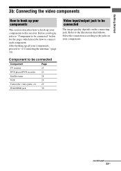
.... Getting Started 3b: Connecting the video components How to hook up your components This section describes how to hook up all your components to this receiver. continued 23US After hooking up your components, proceed to be connected The image quality depends on your components. Before you begin, refer to "Component to...
.... Getting Started 3b: Connecting the video components How to hook up your components This section describes how to hook up all your components to this receiver. continued 23US After hooking up your components, proceed to be connected The image quality depends on your components. Before you begin, refer to "Component to...


