Operating Instructions
Page 3
...Electrical & Electronic Equipment (Applicable in the text, for example, "Models of area code AA only". R SURROUND SPEAKERS R FRONT A RL RL FRONT B SPEAKERS Area code Any differences in operation, according to conserve natural resources. For more detailed information about recycling of this manual...8226; The instructions in this product is used for model STR-DG500. You can also use the controls on the receiver if they have the same or similar names as household waste. SURROUND BACK L L + - + - This receiver incorporates Dolby* Digital and Pro Logic Surround and the DTS...
...Electrical & Electronic Equipment (Applicable in the text, for example, "Models of area code AA only". R SURROUND SPEAKERS R FRONT A RL RL FRONT B SPEAKERS Area code Any differences in operation, according to conserve natural resources. For more detailed information about recycling of this manual...8226; The instructions in this product is used for model STR-DG500. You can also use the controls on the receiver if they have the same or similar names as household waste. SURROUND BACK L L + - + - This receiver incorporates Dolby* Digital and Pro Logic Surround and the DTS...
Operating Instructions
Page 4
... the audio components.........15 3b: Connecting the video components ........18 4: Connecting the antennas 24 5: Preparing the receiver and the remote .....25 6: Selecting the speaker system 26 7: Calibrating the appropriate settings automatically (AUTO CALIBRATION 27 8: Adjusting the speaker levels and balance (TEST TONE 30 Playback Selecting a component 31 Listening/Watching a component 32 Amplifier Operations...
... the audio components.........15 3b: Connecting the video components ........18 4: Connecting the antennas 24 5: Preparing the receiver and the remote .....25 6: Selecting the speaker system 26 7: Calibrating the appropriate settings automatically (AUTO CALIBRATION 27 8: Adjusting the speaker levels and balance (TEST TONE 30 Playback Selecting a component 31 Listening/Watching a component 32 Amplifier Operations...

Operating Instructions
Page 5
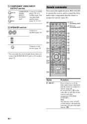
... remote commander. E Remote sensor Receives signals from children. B SPEAKERS (OFF/A/B/A+B) Press to turn the receiver on or off (page 25, 32, 33, 53, 55, 72). Name Function A ?/1 Press to select OFF, A, B, A+B of parts Front panel 12 34 5 67 8 ?/1 SPEAKERS (OFF/A/B /A+B) AUTO CAL MIC PHONES VIDEO 3 IN/PORTABLE AV IN VIDEO L AUDIO R MULTI CHANNEL DECODING DISPLAY INPUT MODE...
... remote commander. E Remote sensor Receives signals from children. B SPEAKERS (OFF/A/B/A+B) Press to turn the receiver on or off (page 25, 32, 33, 53, 55, 72). Name Function A ?/1 Press to select OFF, A, B, A+B of parts Front panel 12 34 5 67 8 ?/1 SPEAKERS (OFF/A/B /A+B) AUTO CAL MIC PHONES VIDEO 3 IN/PORTABLE AV IN VIDEO L AUDIO R MULTI CHANNEL DECODING DISPLAY INPUT MODE...

Operating Instructions
Page 6
...high quality analog sound (page 52). P TUNING MODE Press to adjust the volume level of all speakers at the same time (page 30, 31, 32, 33). H MASTER VOLUME Turn to select ... (MOVIE, MUSIC) (page 49). Name Function R VIDEO 3 IN/ To connect a camcorder or PORTABLE AV IN video game (page 23, 31). T PHONES jack Connects to select information displayed on the display ...(page 59, 62). Name Function F DISPLAY Press to a headphone (page 68). 6GB J MULTI CH IN Press to select the audio directly from the components connected to both digital and analog jacks (...
...high quality analog sound (page 52). P TUNING MODE Press to adjust the volume level of all speakers at the same time (page 30, 31, 32, 33). H MASTER VOLUME Turn to select ... (MOVIE, MUSIC) (page 49). Name Function R VIDEO 3 IN/ To connect a camcorder or PORTABLE AV IN video game (page 23, 31). T PHONES jack Connects to select information displayed on the display ...(page 59, 62). Name Function F DISPLAY Press to a headphone (page 68). 6GB J MULTI CH IN Press to select the audio directly from the components connected to both digital and analog jacks (...

Operating Instructions
Page 7
..., be sure that you have made digital connections and that INPUT MODE is activated (page 48). DIGITAL EX" lights up when the receiver applies Pro Logic processing to 2 channel signals in order to "ANALOG" (page 60). About the indicators on the display Getting Started 123 4 5 67 89 SW LFE SP... Function Lights up when DTS signals are decoded. Lights up when the Pro Logic II Movie/Music/ Game decoder is not set to the speaker system used. Note When playing a Dolby Digital format disc, be sure that you have made digital connections and that INPUT MODE is activated. ...
..., be sure that you have made digital connections and that INPUT MODE is activated (page 48). DIGITAL EX" lights up when the receiver applies Pro Logic processing to 2 channel signals in order to "ANALOG" (page 60). About the indicators on the display Getting Started 123 4 5 67 89 SW LFE SP... Function Lights up when DTS signals are decoded. Lights up when the Pro Logic II Movie/Music/ Game decoder is not set to the speaker system used. Note When playing a Dolby Digital format disc, be sure that you have made digital connections and that INPUT MODE is activated. ...

Operating Instructions
Page 8
... signal being played back. For details on the speaker settings). Lights up when using the receiver to "NO" (page 37) Sound Field: A.F.D. Lights up when ANALOG DIRECT is activated (page 35). Name P Playback channel indicators L R C SL SR S SB Function The letters (L, C, R, etc.) indicate the channels being input through the COAXIAL jack, or when INPUT...
... signal being played back. For details on the speaker settings). Lights up when using the receiver to "NO" (page 37) Sound Field: A.F.D. Lights up when ANALOG DIRECT is activated (page 35). Name P Playback channel indicators L R C SL SR S SB Function The letters (L, C, R, etc.) indicate the channels being input through the COAXIAL jack, or when INPUT...
Operating Instructions
Page 9
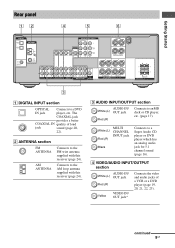
... A RL RL FRONT B SPEAKERS 3 A DIGITAL INPUT section OPTICAL Connects to an MD deck or CD player, etc. (page 17). D VIDEO/AUDIO INPUT/OUTPUT section AUDIO IN/ White (L) OUT jack .... Connects to a Super Audio CD player or DVD player which has an analog audio jack for 5.1 channel sound (page 16). continued 9GB White (L) Red (R) MULTI CHANNEL INPUT jack Black Connects to the AM loop antenna supplied with this receiver (page 24). SURROUND BACK L L + - + - Getting Started Rear panel 12 4 5 6 DIGITAL OPTICAL VIDEO 1 IN VIDEO 2 IN...
... A RL RL FRONT B SPEAKERS 3 A DIGITAL INPUT section OPTICAL Connects to an MD deck or CD player, etc. (page 17). D VIDEO/AUDIO INPUT/OUTPUT section AUDIO IN/ White (L) OUT jack .... Connects to a Super Audio CD player or DVD player which has an analog audio jack for 5.1 channel sound (page 16). continued 9GB White (L) Red (R) MULTI CHANNEL INPUT jack Black Connects to the AM loop antenna supplied with this receiver (page 24). SURROUND BACK L L + - + - Getting Started Rear panel 12 4 5 6 DIGITAL OPTICAL VIDEO 1 IN VIDEO 2 IN...
Operating Instructions
Page 10
...AUTO SLEEP CAL AV ?/1 TV ?/1 ?/1 (on/standby) switch wf 2 TV ?/1, ?/1 SYSTEM STANDBY (on or off the receiver and other components (SYSTEM STANDBY). REPLAY ADVANCE PRESET + .< > < TUNING - You OUTPUT can use the supplied remote RM-AAU005 to operate the receiver and to control the Sony audio/video ...will turn on /standby) switch VIDEO 1 VIDEO 2 VIDEO 3 DVD wd MD/TAPE SA-CD/CD TUNER AMP MENU 3 ws 2CH A.F.D. F SPEAKER section Connects to a DVD VIDEO player, TV, or a INPUT/ satellite tuner. E COMPONENT VIDEO INPUT/ OUTPUT section Green Blue Red COMPONENT Connects to...
...AUTO SLEEP CAL AV ?/1 TV ?/1 ?/1 (on/standby) switch wf 2 TV ?/1, ?/1 SYSTEM STANDBY (on or off the receiver and other components (SYSTEM STANDBY). REPLAY ADVANCE PRESET + .< > < TUNING - You OUTPUT can use the supplied remote RM-AAU005 to operate the receiver and to control the Sony audio/video ...will turn on /standby) switch VIDEO 1 VIDEO 2 VIDEO 3 DVD wd MD/TAPE SA-CD/CD TUNER AMP MENU 3 ws 2CH A.F.D. F SPEAKER section Connects to a DVD VIDEO player, TV, or a INPUT/ satellite tuner. E COMPONENT VIDEO INPUT/ OUTPUT section Green Blue Red COMPONENT Connects to...

Operating Instructions
Page 11
... to adjust the TV volume level. Press to mute the sound. To turn the receiver on or off all speakers at the same time. D MOVIE, MUSIC Press to select FM monaural or stereo.... MEMORY J MUTING K TV VOL +a)/- Press to adjust the volume level of all components, press ?/1 and AV ?/1 (A) at the same time (SYSTEM STANDBY). TV CH +/- return to enter direct tuning mode. Name Function... deck. (Also starts recording with orange printing. Name Function L ./> Press to select preset TV channels. and TV (M) at the same time to skip tracks of the VCR, CD player, MD...
... to adjust the TV volume level. Press to mute the sound. To turn the receiver on or off all speakers at the same time. D MOVIE, MUSIC Press to select FM monaural or stereo.... MEMORY J MUTING K TV VOL +a)/- Press to adjust the volume level of all components, press ?/1 and AV ?/1 (A) at the same time (SYSTEM STANDBY). TV CH +/- return to enter direct tuning mode. Name Function... deck. (Also starts recording with orange printing. Name Function L ./> Press to select preset TV channels. and TV (M) at the same time to skip tracks of the VCR, CD player, MD...
Operating Instructions
Page 13
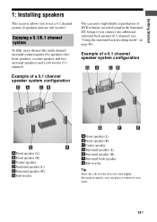
... can place it wherever you want. 13GB Enjoying a 5.1/6.1 channel system To fully enjoy theater-like multi channel surround sound requires five speakers (two front speakers, a center speaker, and two surround speakers) and a sub woofer (5.1 channel). Getting Started 1: Installing speakers This receiver allows you to use a 6.1 channel system (6 speakers and one additional surround back speaker (6.1 channel) (see "Using the surround back decoding mode" on page...
... can place it wherever you want. 13GB Enjoying a 5.1/6.1 channel system To fully enjoy theater-like multi channel surround sound requires five speakers (two front speakers, a center speaker, and two surround speakers) and a sub woofer (5.1 channel). Getting Started 1: Installing speakers This receiver allows you to use a 6.1 channel system (6 speakers and one additional surround back speaker (6.1 channel) (see "Using the surround back decoding mode" on page...

Operating Instructions
Page 14
... 2 VIDEO 1 L AUDIO CENTER OUT R SUB FRONT SURROUND WOOFER SUB MULTI CH IN WOOFER + - + - R SURROUND SPEAKERS R FRONT A RL RL FRONT B SPEAKERS B D E A Monaural audio cord (not supplied) B Speaker cords (not supplied) AFront speaker A (L) BFront speaker A (R) CCenter speaker DSurround speaker (L) ESurround speaker (R) FSurround back speaker GSub wooferb) 14GB B A a)If you have an additional front speaker system, connect them to a sub woofer, then sound may...
... 2 VIDEO 1 L AUDIO CENTER OUT R SUB FRONT SURROUND WOOFER SUB MULTI CH IN WOOFER + - + - R SURROUND SPEAKERS R FRONT A RL RL FRONT B SPEAKERS B D E A Monaural audio cord (not supplied) B Speaker cords (not supplied) AFront speaker A (L) BFront speaker A (R) CCenter speaker DSurround speaker (L) ESurround speaker (R) FSurround back speaker GSub wooferb) 14GB B A a)If you have an additional front speaker system, connect them to a sub woofer, then sound may...

Operating Instructions
Page 16
... If your DVD or Super Audio CD player is equipped with multi channel output jacks, you will need to adjust the level of this receiver to enjoy multi channel sound. Alternatively, the multi channel input jacks can connect it to connect an external multi channel decoder. SURROUND BACK L L + - + - DVD player...IN AUDIO IN AUDIO OUT AUDIO IN DVD VIDEO 2 VIDEO 1 L AUDIO CENTER OUT R SUB FRONT SURROUND WOOFER SUB MULTI CH IN WOOFER CENTER + - R SURROUND SPEAKERS R FRONT A A Audio cord (not supplied) B Monaural audio cord (not supplied) 16GB Note When you make connections to the...
... If your DVD or Super Audio CD player is equipped with multi channel output jacks, you will need to adjust the level of this receiver to enjoy multi channel sound. Alternatively, the multi channel input jacks can connect it to connect an external multi channel decoder. SURROUND BACK L L + - + - DVD player...IN AUDIO IN AUDIO OUT AUDIO IN DVD VIDEO 2 VIDEO 1 L AUDIO CENTER OUT R SUB FRONT SURROUND WOOFER SUB MULTI CH IN WOOFER CENTER + - R SURROUND SPEAKERS R FRONT A A Audio cord (not supplied) B Monaural audio cord (not supplied) 16GB Note When you make connections to the...

Operating Instructions
Page 17
...-CD/CD R OUT IN MD/TAPE L L R R AUDIO IN AUDIO IN AUDIO OUT AUDIO IN DVD VIDEO 2 VIDEO 1 L AUDIO CENTER OUT R SUB FRONT SURROUND WOOFER SUB MULTI CH IN WOOFER CENTER + - R SURROUND SPEAKERS R FRONT A A Audio cord (not supplied) 17GB
...-CD/CD R OUT IN MD/TAPE L L R R AUDIO IN AUDIO IN AUDIO OUT AUDIO IN DVD VIDEO 2 VIDEO 1 L AUDIO CENTER OUT R SUB FRONT SURROUND WOOFER SUB MULTI CH IN WOOFER CENTER + - R SURROUND SPEAKERS R FRONT A A Audio cord (not supplied) 17GB
Operating Instructions
Page 19
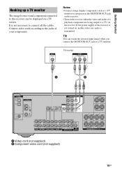
... It is transmitted. R SURROUND SPEAKERS R FRONT A A Video cord (not supplied) B Component video cord (not supplied) 19GB Notes • Connect image display components such as a TV monitor or a projector to the MONITOR OUT jack on the receiver. • Turn on a ...monitor. Connect video cords according to the jacks of a playback component are being output to a TV via the receiver. TV monitor A B DIGITAL OPTICAL VIDEO 1 IN VIDEO 2 IN ANTENNA AM COMPONENT VIDEO ASSIGNABLE Y MONITOR ... VIDEO 2 VIDEO 1 L AUDIO CENTER OUT R SUB FRONT SURROUND WOOFER SUB MULTI CH IN WOOFER CENTER + -
... It is transmitted. R SURROUND SPEAKERS R FRONT A A Video cord (not supplied) B Component video cord (not supplied) 19GB Notes • Connect image display components such as a TV monitor or a projector to the MONITOR OUT jack on the receiver. • Turn on a ...monitor. Connect video cords according to the jacks of a playback component are being output to a TV via the receiver. TV monitor A B DIGITAL OPTICAL VIDEO 1 IN VIDEO 2 IN ANTENNA AM COMPONENT VIDEO ASSIGNABLE Y MONITOR ... VIDEO 2 VIDEO 1 L AUDIO CENTER OUT R SUB FRONT SURROUND WOOFER SUB MULTI CH IN WOOFER CENTER + -
Operating Instructions
Page 20
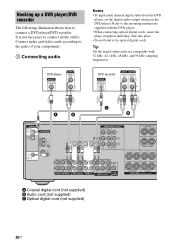
...IN WOOFER CENTER + - It is not necessary to the jacks of your components. 1 Connecting audio Notes • To input multi channel digital audio from the DVD player, set the digital audio output setting on the DVD player. Connect audio and video cords according to...; When connecting optical digital cords, insert the plugs straight in until they click into place. • Do not bend or tie optical digital cords. R SURROUND SPEAKERS R FRONT A A Coaxial digital cord (not supplied) B Audio cord (not supplied) C Optical digital cord (not supplied) 20GB Hooking up a DVD player/DVD ...
...IN WOOFER CENTER + - It is not necessary to the jacks of your components. 1 Connecting audio Notes • To input multi channel digital audio from the DVD player, set the digital audio output setting on the DVD player. Connect audio and video cords according to...; When connecting optical digital cords, insert the plugs straight in until they click into place. • Do not bend or tie optical digital cords. R SURROUND SPEAKERS R FRONT A A Coaxial digital cord (not supplied) B Audio cord (not supplied) C Optical digital cord (not supplied) 20GB Hooking up a DVD player/DVD ...
Operating Instructions
Page 21
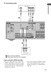
...L R R AUDIO IN AUDIO IN AUDIO OUT AUDIO IN DVD VIDEO 2 VIDEO 1 L AUDIO CENTER OUT R SUB FRONT SURROUND WOOFER SUB MULTI CH IN WOOFER CENTER + - R SURROUND SPEAKERS R FRONT A A DVD recorder A Video cord (not supplied) B Component video cord (not supplied) If you can be displayed on the... remote so that it can use the button to change the factory setting of the VIDEO 1 input button on the receiver's display. For details,...
...L R R AUDIO IN AUDIO IN AUDIO OUT AUDIO IN DVD VIDEO 2 VIDEO 1 L AUDIO CENTER OUT R SUB FRONT SURROUND WOOFER SUB MULTI CH IN WOOFER CENTER + - R SURROUND SPEAKERS R FRONT A A DVD recorder A Video cord (not supplied) B Component video cord (not supplied) If you can be displayed on the... remote so that it can use the button to change the factory setting of the VIDEO 1 input button on the receiver's display. For details,...

Operating Instructions
Page 22
... L L R R AUDIO IN AUDIO IN AUDIO OUT AUDIO IN DVD VIDEO 2 VIDEO 1 L AUDIO CENTER OUT R SUB FRONT SURROUND WOOFER SUB MULTI CH IN WOOFER CENTER + - Tip All the digital audio jacks are compatible with 32 kHz, 44.1 kHz, 48 kHz, and 96 kHz sampling ... straight in until they click into place. • Do not bend or tie optical digital cords. It is not necessary to connect a satellite tuner. R SURROUND SPEAKERS R FRONT A A Audio cord (not supplied) B Optical digital cord (not supplied) C Video cord (not supplied) D Component video cord (not supplied) 22GB SURROUND BACK L ...
... L L R R AUDIO IN AUDIO IN AUDIO OUT AUDIO IN DVD VIDEO 2 VIDEO 1 L AUDIO CENTER OUT R SUB FRONT SURROUND WOOFER SUB MULTI CH IN WOOFER CENTER + - Tip All the digital audio jacks are compatible with 32 kHz, 44.1 kHz, 48 kHz, and 96 kHz sampling ... straight in until they click into place. • Do not bend or tie optical digital cords. It is not necessary to connect a satellite tuner. R SURROUND SPEAKERS R FRONT A A Audio cord (not supplied) B Optical digital cord (not supplied) C Video cord (not supplied) D Component video cord (not supplied) 22GB SURROUND BACK L ...

Operating Instructions
Page 23
...L R R AUDIO IN AUDIO IN AUDIO OUT AUDIO IN DVD VIDEO 2 VIDEO 1 L AUDIO CENTER OUT R SUB FRONT SURROUND WOOFER SUB MULTI CH IN WOOFER CENTER + - Getting Started Hooking up components with analog video and audio jack The following illustration shows how to connect a component... which has analog jacks such as a VCR, etc. R SURROUND SPEAKERS R FRONT A To the VIDEO 3 IN/PORTABLE AV IN jacks (Front panel) VIDEO 3 IN/PORTABLE AV IN Camcorder/ video game A A Audio/video cord (not supplied) 23GB SURROUND BACK L L + - +...
...L R R AUDIO IN AUDIO IN AUDIO OUT AUDIO IN DVD VIDEO 2 VIDEO 1 L AUDIO CENTER OUT R SUB FRONT SURROUND WOOFER SUB MULTI CH IN WOOFER CENTER + - Getting Started Hooking up components with analog video and audio jack The following illustration shows how to connect a component... which has analog jacks such as a VCR, etc. R SURROUND SPEAKERS R FRONT A To the VIDEO 3 IN/PORTABLE AV IN jacks (Front panel) VIDEO 3 IN/PORTABLE AV IN Camcorder/ video game A A Audio/video cord (not supplied) 23GB SURROUND BACK L L + - +...
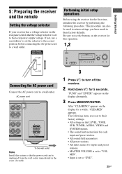
Operating Instructions
Page 25
... off the receiver. 2 Hold down ?/1 for 5 seconds. After "CLEARING" appears on the display for this system so that the voltage selector is set to a wall outlet. R FRONT A RL RL FRONT B SPEAKERS To the wall outlet Note Install this operation. 1,2 ?/1 SPEAKERS (OFF/A/B /A+B) AUTO CAL MIC PHONES VIDEO 3 IN/PORTABLE AV IN VIDEO L AUDIO R MULTI CHANNEL DECODING DISPLAY...
... off the receiver. 2 Hold down ?/1 for 5 seconds. After "CLEARING" appears on the display for this system so that the voltage selector is set to a wall outlet. R FRONT A RL RL FRONT B SPEAKERS To the wall outlet Note Install this operation. 1,2 ?/1 SPEAKERS (OFF/A/B /A+B) AUTO CAL MIC PHONES VIDEO 3 IN/PORTABLE AV IN VIDEO L AUDIO R MULTI CHANNEL DECODING DISPLAY...
Operating Instructions
Page 26
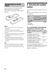
...the batteries should last for this operation. ?/1 SPEAKERS (OFF/A/B /A+B) AUTO CAL MIC PHONES VIDEO 3 IN/PORTABLE AV IN VIDEO L AUDIO R MULTI CHANNEL DECODING DISPLAY INPUT MODE INPUT SELECTOR MASTER VOLUME MEMORY.../ TUNING ENTER MODE TUNING 2CH A.F.D. Be sure to both the SPEAKERS FRONT A and B terminals (parallel connection) SP A SP B SP A and SP B To turn off the speaker output, press SPEAKERS (OFF/A/B/A+B) repeatedly until the "SP A" and "SP B" indicators on the receiver...
...the batteries should last for this operation. ?/1 SPEAKERS (OFF/A/B /A+B) AUTO CAL MIC PHONES VIDEO 3 IN/PORTABLE AV IN VIDEO L AUDIO R MULTI CHANNEL DECODING DISPLAY INPUT MODE INPUT SELECTOR MASTER VOLUME MEMORY.../ TUNING ENTER MODE TUNING 2CH A.F.D. Be sure to both the SPEAKERS FRONT A and B terminals (parallel connection) SP A SP B SP A and SP B To turn off the speaker output, press SPEAKERS (OFF/A/B/A+B) repeatedly until the "SP A" and "SP B" indicators on the receiver...


