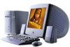
System Reference Manual (primary manual)
Page 2
...separate user license agreement. PS/2 is subject to this product. Model Number: PCV-J150 Serial Number ii IN NO EVENT SHALL SONY ELECTRONICS INC. Financial services may require prior arrangements with this manual or the information contained herein at any machinereadable form without notice. Record the ...transported or used outside the United States. Updates and additions to the model and serial number when you call your VAIO® computer. This manual and the software described herein, in whole or in part, may not be identical to any time without prior ...
System Reference Manual (primary manual)
Page 5
This equipment has been tested and found to comply with the instructions, may be attached to operate this computer product. However, there is no guarantee that interference will not occur in interference to connect peripherals must ... grounded. Only peripherals (computer input/output devices, terminals, printers, etc.) that may result in a particular installation. All cables used in this manual could void your authority to this equipment. Operation with Part 15 of Conformity Trade Name: SONY Model No.: PCV-J150 Responsible Party: Sony Electronics Inc. Address: ...
System Reference Manual (primary manual)
Page 12
Fax/Modem Card Chapter 6 - CMOS Setup Options Main Screen 69 Advanced Screen 71 Power Screen 72 Boot Screen 73 Exit Screen 74 Chapter 8 - xii VAIO® Reference Manual Installing an Add-In Card 26 Removing an Add-in Card 28 Replacing the Lithium Battery 30 Removing a Memory Module 33 Installing System Memory 36...
System Reference Manual (primary manual)
Page 15
Internal components are identified in the appropriate section of the VAIO® Computer. Chapter 1 Identifying Components The following sections identify and describe each component that is visible from the exterior of this manual. 1
System Reference Manual (primary manual)
Page 18
Automatically opens and closes the CD-RW drive tray. 4 VAIO® Reference Manual Buttons and Switches Eject hole CD-RW disceject Diskette eject Power/Standby FRNTPNLB.VSD Button or switch Power/Standby switch Diskette eject button CD-RW disc eject button Description Turns system power on, off, or into standby mode. Ejects a diskette.
System Reference Manual (primary manual)
Page 22
Do not plug a phone into this connector.) 8 VAIO® Reference Manual Icon Description MONITOR connector LINE (for telephone line from primary service jack) TELEPHONE (for phone) i.LINK® (IEEE1394) interface Ethernet connector (10Base-T/100Base-TX) (This connector is for LAN use only.
System Reference Manual (primary manual)
Page 24
10 VAIO® Reference Manual PRINTER Connector The PRINTER connector is a standard 25-pin DB-25 female connector. 13 25 14 1 KY0005.VSD MONITOR The MONITOR connector is a standard 15-pin female high-density VGAtype connector. 10 15 5 11 1 6 KY0004.VSD
System Reference Manual (primary manual)
Page 26
...-1394) On back of system KY0087.VSD Ethernet Connector The Ethernet connector is for information on operating conditions and proper connections. 12 VAIO® Reference Manual i.LINK® (IEEE1394) Connector The 6-pin i.LINK connector on the software applications, operating system and i.LINK-compatible devices. The...maximum power of 6 watts. ✍ i.LINK is a trademark of Sony used only to your i.LINK-compatible device for LAN use only. Ethernet On back of the system can supply power from the computer to the documentation that a product contains an IEEE 1394 connection. All ...
System Reference Manual (primary manual)
Page 30
...ESC to select a menu from any open files and exit the Microsoft® Windows® operating system. 1 Reboot the system. 2 When the Sony logo appears, press F3. If a submenu contains items with a triangle, there is another layer of the screen. Before rebooting the system, save any... top-level screen and follow the prompts. Press for modifying the system configuration. 16 VAIO® Reference Manual Accessing the BIOS Setup Utility You must access the BIOS Setup Utility to make changes to modify a setting. Each menu presents ...
System Reference Manual (primary manual)
Page 32
... of inactivity (in minutes) that you want to specify the period of inactivity (in minutes) before your computer goes on standby when your computer goes in the hibernate state. Power is reactivated when you press spacebar on AC power. 18 VAIO® Reference Manual The System standby option allows you to elapse before your...
System Reference Manual (primary manual)
Page 36
22 VAIO® Reference Manual Removing the Side Panel You must remove the side panel to access the system board, add-in cards, power supply, battery, memory, and internal drives. 1 From the rear of the unit, remove the single screw on the right side. 2 Slide back the panel about ½ inch, then lift out. KY0064B.VSD
System Reference Manual (primary manual)
Page 38
24 VAIO® Reference Manual Replacing the Front Panel 1 Insert the two flat plastic tabs (located on the top of the front panel) into the slots at the top of the chassis. 2 Push the bottom of the front panel in until the tabs snap into place. Front panel 1 KY0093.VSD
System Reference Manual (primary manual)
Page 40
... the bottom of the bracket fits into the PCI slot connector. Use a gentle rocking motion, pressing down until the card is fully inserted. 26 VAIO® Reference Manual Installing an Add-In Card ! KY0070.VSD 5 Replace the screw that secures the card. 6 Attach any necessary cables to the card (see the... the bracket fits snugly against the chassis lip after the card is fully seated. ✍ Align the card's bracket so that the top of the computer and all attached peripherals, and then unplug the power cord. 1 Remove the cover (see "Removing the Side Panel" on page 22). 2 Locate an ...
System Reference Manual (primary manual)
Page 42
28 VAIO® Reference Manual 5 If you do not replace the card or install another add-in card, install a slot cover over the vacant slot at the rear of the chassis (see "Covering an Open I/O Slot" on page 41). 6 Replace the cover (see "Replacing the Side Panel" on page 25).
System Reference Manual (primary manual)
Page 44
... side panel (see "Removing an Add-in Card" on page 28) to gain access to disconnect some cables. ! 30 VAIO® Reference Manual 8 If necessary, remove any cables that came with the new battery. 11 Insert the new battery into the battery holder, ...with the plus (+) side up, and gently press down until the battery snaps into place. ✍ The Sony CR2032 battery..."Replacing the Side Panel" on page 25). 15 Reconnect the power cord and turn on the computer.
System Reference Manual (primary manual)
Page 46
Before opening the system unit, save any open files, exit the Windows® operating system, turn off the power of the computer and all attached peripherals, and then unplug the power cord. 1 Remove the left side cover (see "Removing the Side Panel" on page 22). 2 Remove the ... chassis is the same screw that secures the side panel to remove a memory module if you change the memory configuration or replace a bad module. ! 32 VAIO® Reference Manual Removing a Memory Module You may need to the chassis.
System Reference Manual (primary manual)
Page 48
...the power supply slips into the slot in the CD-RW drive. Your computer automatically recognizes any exposed metal part of the memory module and lift out. No further action is required. 34 VAIO® Reference Manual 5 Grasp one edge of the chassis to discharge static electricity in your ...body before handling the memory module. 6 To install system memory, see "Replacing the Side Panel" on page 25). 9 Reconnect the power cord and turn on the computer. Touch any change ...
System Reference Manual (primary manual)
Page 50
AUR001.VSD ✍ The screw that secures the power supply to the chassis is the same screw that secures the side panel to the chassis. 7 If necessary, remove the memory module you wish to replace (see "Removing a Memory Module" on page 33). 36 VAIO® Reference Manual 6 Remove the power supply by lifting it up and rest it upside down over the corner of the chassis where the CD-RW and floppy drives are located.
System Reference Manual (primary manual)
Page 52
38 VAIO® Reference Manual 11 Replace the power supply by sliding it down the rails on each side of the chassis opening until the metal tab on the power supply slips into slot in the CD-RW drive. Tab fits into the slot in CD-RW drive AUR002.VSD 12 Replace the side panel (see "Replacing the Side Panel" on page 25). 13 Reconnect the power cord and turn on the computer. No further action is required. Your computer automatically recognizes the extra memory and will configure itself accordingly when you turn on the computer.
System Reference Manual (primary manual)
Page 54
If air escapes, the components inside the computer cannot be properly cooled. This may damage some components, especially the main processor (which generates the most heat). 1 Slide the tip of the slot cover (.... 3 Replace the screw (removed earlier) to secure the I /O Slot Slot covers prevent air from escaping through the empty hole. All add-in the chassis. 40 VAIO® Reference Manual Covering an Open I /O slot cover.