Operating Instructions
Page 42
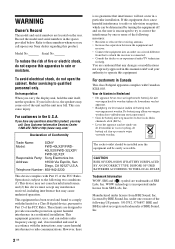
... with the limits for help. This equipment has been tested and found to comply with Part 15 of Conformity Trade Name: SONY Model: FWD-40LX2F/FWD- 40LX2X/FWD-32LX2F/ FWD-32LX2X Responsible Party: Sony Electronics Inc. NL The socket-outlet should be installed near the equipment and be determined...harmful interference, and (2) this device must accept any interference received, including interference that any questions about this product, you carry the display unit, hold the unit itself, not the speakers. Licensed by one or more of the FCC Rules. Model No. Address: ...
... with the limits for help. This equipment has been tested and found to comply with Part 15 of Conformity Trade Name: SONY Model: FWD-40LX2F/FWD- 40LX2X/FWD-32LX2F/ FWD-32LX2X Responsible Party: Sony Electronics Inc. NL The socket-outlet should be installed near the equipment and be determined...harmful interference, and (2) this device must accept any interference received, including interference that any questions about this product, you carry the display unit, hold the unit itself, not the speakers. Licensed by one or more of the FCC Rules. Model No. Address: ...
Operating Instructions
Page 43
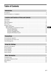
Table of Contents Introduction Precautions ...4 Recommendations on Installation 6 Location and Function of Parts and Controls Front Panel...7 Side Panel...8 Optional Adaptors ...10 Rear Panel ...11 Remote Control ...12 Button Description...12 Special Buttons on the Remote Control 14 GB Using the Wide Mode...14 Using the PAP Setting 15 ... Management...18 Using the Settings Overview of the Menus ...20 Picture Settings ...22 Sound Settings...24 Screen Settings...25 Setup Settings...29 Other Information Troubleshooting ...32 Input Signal Reference Chart 33 Specifications ...34 Index ...36 3 GB
Table of Contents Introduction Precautions ...4 Recommendations on Installation 6 Location and Function of Parts and Controls Front Panel...7 Side Panel...8 Optional Adaptors ...10 Rear Panel ...11 Remote Control ...12 Button Description...12 Special Buttons on the Remote Control 14 GB Using the Wide Mode...14 Using the PAP Setting 15 ... Management...18 Using the Settings Overview of the Menus ...20 Picture Settings ...22 Sound Settings...24 Screen Settings...25 Setup Settings...29 Other Information Troubleshooting ...32 Input Signal Reference Chart 33 Specifications ...34 Index ...36 3 GB
Operating Instructions
Page 47
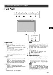
...8226; Lights up in red when the display is displayed. 4 // • Increases (+) or decreases (−) the volume. • In the menu screen, these buttons work as the "Set" button. • This button switches the input signal when it on again. 6 Sony logo The Sony logo lights up in the OPTION 1/..., soon after turning it off (standby). Location and Function of Parts and Controls Front Panel GB 1 MENU (page 20) 2 / (INPUT) • In the menu screen, this button works as up/down buttons ( / ). 51 Switches the display on or off (standby). When an optional adaptor is not installed...
...8226; Lights up in red when the display is displayed. 4 // • Increases (+) or decreases (−) the volume. • In the menu screen, these buttons work as the "Set" button. • This button switches the input signal when it on again. 6 Sony logo The Sony logo lights up in the OPTION 1/..., soon after turning it off (standby). Location and Function of Parts and Controls Front Panel GB 1 MENU (page 20) 2 / (INPUT) • In the menu screen, this button works as up/down buttons ( / ). 51 Switches the display on or off (standby). When an optional adaptor is not installed...

Operating Instructions
Page 51
...17. By connecting the speakers SS-SP40FW/32FW (not supplied) to this socket and to a wall outlet. Please be sure to install the display stand SU-42FW/32FW (not supplied). 11 GB For more details on how to route the speaker cords, see the operating manual that came... with a greater sense of presence. Use these hooks to connect the speakers correctly. Rear Panel GB R L SPEAKER Parts 1 AC IN socket 2 SPEAKER socket 3 Stand installation hooks Description Connect the supplied AC power cord to this socket, you connect the AC...
...17. By connecting the speakers SS-SP40FW/32FW (not supplied) to this socket and to a wall outlet. Please be sure to install the display stand SU-42FW/32FW (not supplied). 11 GB For more details on how to route the speaker cords, see the operating manual that came... with a greater sense of presence. Use these hooks to connect the speakers correctly. Rear Panel GB R L SPEAKER Parts 1 AC IN socket 2 SPEAKER socket 3 Stand installation hooks Description Connect the supplied AC power cord to this socket, you connect the AC...
Operating Instructions
Page 59
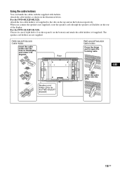
...the hinge part to the slits on the top and on the display and rotate it 90 degrees. For the FWD-40LX2F/40LX2X: Attach the two cable holders (×4 supplied) to open the hooking nails. Attach the cable holders as shown in the illustration below. For the FWD-32LX2F/32LX2X: ...Choose six out of the display. GB Speaker cord holder (Only for the FWD-40LX2F/ 40LX2X) Insert the cable holder into the hole on the bottom respectively. The speaker cord ...
...the hinge part to the slits on the top and on the display and rotate it 90 degrees. For the FWD-40LX2F/40LX2X: Attach the two cable holders (×4 supplied) to open the hooking nails. Attach the cable holders as shown in the illustration below. For the FWD-32LX2F/32LX2X: ...Choose six out of the display. GB Speaker cord holder (Only for the FWD-40LX2F/ 40LX2X) Insert the cable holder into the hole on the bottom respectively. The speaker cord ...

Operating Instructions
Page 63
... "Picture Mode" is no signal currently being input, none of the options of 4 colors : red, green, yellow, blue, and you can check and see which part of the "Picture" setting can highlight specific colors in the image. For PC Input Picture Picture Mode : Picture Mode Reset Picture : Brightness : Color : Hue : Color...
... "Picture Mode" is no signal currently being input, none of the options of 4 colors : red, green, yellow, blue, and you can check and see which part of the "Picture" setting can highlight specific colors in the image. For PC Input Picture Picture Mode : Picture Mode Reset Picture : Brightness : Color : Hue : Color...
Operating Instructions
Page 67
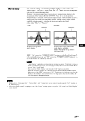
...formats will be selected. 27 GB To show full signal on the Front Panel to be continually turned on, and "Off" causes the POWER/STANDBY indicator on each display. Notes • "Multi Display" can display an enlarged picture keeping the current "Wide Mode" setting as much as shown... shift. By simply selecting either "Tiles" or "Window". Part of no signal currently being input, none of the "Screen" settings options, except for "PAP Setting" and "Multi Display" can be available as possible for connecting multiple displays to form a video wall. Select either format, suitable picture...
...formats will be selected. 27 GB To show full signal on the Front Panel to be continually turned on, and "Off" causes the POWER/STANDBY indicator on each display. Notes • "Multi Display" can display an enlarged picture keeping the current "Wide Mode" setting as much as shown... shift. By simply selecting either "Tiles" or "Window". Part of no signal currently being input, none of the "Screen" settings options, except for "PAP Setting" and "Multi Display" can be available as possible for connecting multiple displays to form a video wall. Select either format, suitable picture...


