

Instruction Manual
Page 3
... expose you to normal operation. - This will often require extensive work by the manufacturer that are provided for cleaning the exterior of any service or repairs to the set to dangerous voltage or other materials. - Never cover the slots and openings with water for necessary ventilation. If liquid has been spilled...
... expose you to normal operation. - This will often require extensive work by the manufacturer that are provided for cleaning the exterior of any service or repairs to the set to dangerous voltage or other materials. - Never cover the slots and openings with water for necessary ventilation. If liquid has been spilled...
Instruction Manual
Page 8
...the recording cannot be copyrighted. However, there may be repairable. • Do not aim the camera at the sun or other bright light. These points are operational for effective use. Water entering the inside of the camera may cause malfunctions which in some cases may not be...the copyright laws. [ No compensation for if recording or playback is manufactured using extremely high-precision technology so over 99.99% of your camera or recording media, etc. [ On illustrations Illustrations used in sandy or dusty locations may cause malfunctions. • If moisture condensation occurs,...
...the recording cannot be copyrighted. However, there may be repairable. • Do not aim the camera at the sun or other bright light. These points are operational for effective use. Water entering the inside of the camera may cause malfunctions which in some cases may not be...the copyright laws. [ No compensation for if recording or playback is manufactured using extremely high-precision technology so over 99.99% of your camera or recording media, etc. [ On illustrations Illustrations used in sandy or dusty locations may cause malfunctions. • If moisture condensation occurs,...
Instruction Manual
Page 29
...refer to be repaired. Install charged battery pack (page 10). • The battery pack is dead. Turn on the camera. • Install the battery pack correctly (page 11). • The battery pack is on the power. 3 Initialize the settings (page 24). 4 Consult your camera to "Cyber-shot Handbook." 2 ...GB checked when you send your Sony dealer or local authorized Sony service facility. Please understand that you give your consent that the contents of the battery pack to "Cyber-shot Handbook" (PDF). Replace it with a new one minute, and turn on the camera again (page 13). •...
...refer to be repaired. Install charged battery pack (page 10). • The battery pack is dead. Turn on the camera. • Install the battery pack correctly (page 11). • The battery pack is on the power. 3 Initialize the settings (page 24). 4 Consult your camera to "Cyber-shot Handbook." 2 ...GB checked when you send your Sony dealer or local authorized Sony service facility. Please understand that you give your consent that the contents of the battery pack to "Cyber-shot Handbook" (PDF). Replace it with a new one minute, and turn on the camera again (page 13). •...
Instruction Manual
Page 31
..., it discharges gradually, and if you do not use the camera at all for about an hour for the moisture to shoot with the power off. 31 This may cause the camera to malfunction, and in some cases this malfunction cannot be repaired. [ On carrying Do not sit down in a chair or other... settings regardless of your hand. • Do not leave the camera in contact with rubber or vinyl for a long time. [ On...
..., it discharges gradually, and if you do not use the camera at all for about an hour for the moisture to shoot with the power off. 31 This may cause the camera to malfunction, and in some cases this malfunction cannot be repaired. [ On carrying Do not sit down in a chair or other... settings regardless of your hand. • Do not leave the camera in contact with rubber or vinyl for a long time. [ On...

Service Manual
Page 1
DIGITAL STILL CAMERA DSC-W55_L2 9-852-160-33 Sony EMCS Co. 2007I0800-1 © 2007.09 Published by mark 0 or dotted line with part number specified. Replace only with mark 0 are critical for safety. DSC-W55 SERVICE MANUAL Ver. 1.4 2007.09 Revision History How to use Acrobat Reader ...Korea Model Argentine Model Brazilian Model Tourist Model Link SPECIFICATIONS BLOCK DIAGRAMS PRINTED WIRING BOARDS SERVICE NOTE FRAME SCHEMATIC DIAGRAM REPAIR PARTS LIST DISASSEMBLY SCHEMATIC DIAGRAMS • Precaution on Replacing the SY-176 Board The components identified by Kohda TEC ...
DIGITAL STILL CAMERA DSC-W55_L2 9-852-160-33 Sony EMCS Co. 2007I0800-1 © 2007.09 Published by mark 0 or dotted line with part number specified. Replace only with mark 0 are critical for safety. DSC-W55 SERVICE MANUAL Ver. 1.4 2007.09 Revision History How to use Acrobat Reader ...Korea Model Argentine Model Brazilian Model Tourist Model Link SPECIFICATIONS BLOCK DIAGRAMS PRINTED WIRING BOARDS SERVICE NOTE FRAME SCHEMATIC DIAGRAM REPAIR PARTS LIST DISASSEMBLY SCHEMATIC DIAGRAMS • Precaution on Replacing the SY-176 Board The components identified by Kohda TEC ...
Service Manual
Page 3
... the conductor when soldering or unsoldering. Look for parts which, through functioning, show obvious signs of your repair for unsoldered or poorly-soldered connections. Ordinary soldering irons can be used but unleaded solder may DSC-W55_L2 also be careful! • Strong viscosity circuit board (within 3 times). ATTENTION AU COMPOSANT AYANT RAPPORT ... LES NUMÉROS SONT DONNÉS DANS CE MANUEL OU DANS LES SUPPÉMENTS PUBLIÉS PAR SONY. LES COMPOSANTS IDENTIFÉS PAR UNE MARQUE 0 SUR LES DIAGRAMMES SCHÉMATIQUES ET LA LISTE DES PIÈCES SONT CRITIQUES POUR LA S&#...
... the conductor when soldering or unsoldering. Look for parts which, through functioning, show obvious signs of your repair for unsoldered or poorly-soldered connections. Ordinary soldering irons can be used but unleaded solder may DSC-W55_L2 also be careful! • Strong viscosity circuit board (within 3 times). ATTENTION AU COMPOSANT AYANT RAPPORT ... LES NUMÉROS SONT DONNÉS DANS CE MANUEL OU DANS LES SUPPÉMENTS PUBLIÉS PAR SONY. LES COMPOSANTS IDENTIFÉS PAR UNE MARQUE 0 SUR LES DIAGRAMMES SCHÉMATIQUES ET LA LISTE DES PIÈCES SONT CRITIQUES POUR LA S&#...

Service Manual
Page 4
... for Copying or Erasing the Data in Internal Memory 1-2 1-4. DISASSEMBLY 2-1. Overall Block Diagram (1/2 3-1 3-2. Printed Wiring Boards 4-16 4-4. Disassembly 2-2 2-2. Frame Schematic Diagram 4-1 4-2. REPAIR PARTS LIST 5-1. BLOCK DIAGRAMS 3-1. Process After Fixing Flash Error 1-1 1-3. Electrical Parts List 5-6 DSC-W55_L2 - 4 - Power Block Diagram 3-3 4. Exchange Method of Barrier Assy 2-6 2-3. Section TABLE OF CONTENTS Title Page 1. SERVICE NOTE 1-1.
... for Copying or Erasing the Data in Internal Memory 1-2 1-4. DISASSEMBLY 2-1. Overall Block Diagram (1/2 3-1 3-2. Printed Wiring Boards 4-16 4-4. Disassembly 2-2 2-2. Frame Schematic Diagram 4-1 4-2. REPAIR PARTS LIST 5-1. BLOCK DIAGRAMS 3-1. Process After Fixing Flash Error 1-1 1-3. Electrical Parts List 5-6 DSC-W55_L2 - 4 - Power Block Diagram 3-3 4. Exchange Method of Barrier Assy 2-6 2-3. Section TABLE OF CONTENTS Title Page 1. SERVICE NOTE 1-1.
Service Manual
Page 5
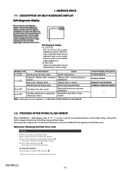
...unit or replacement Abnormality when flash is broken. Insert a new "Memory Stick". SERVICE NOTE 1-1. Note: After repair, be deactivated. Method for Initializing the Flash Error Code Initialize Initializes the setting to perform "1-2. Display Code ...DSC-W55_L2 1-1 PROCESS AFTER FIXING FLASH ERROR". Flash error code can reverse the camera malfunction yourself. (However, contact your Sony dealer or local authorized Sony service facility when you cannot recover from the camera malfunction.) • E: ss: ss Contact your Sony dealer or local authorized Sony...
...unit or replacement Abnormality when flash is broken. Insert a new "Memory Stick". SERVICE NOTE 1-1. Note: After repair, be deactivated. Method for Initializing the Flash Error Code Initialize Initializes the setting to perform "1-2. Display Code ...DSC-W55_L2 1-1 PROCESS AFTER FIXING FLASH ERROR". Flash error code can reverse the camera malfunction yourself. (However, contact your Sony dealer or local authorized Sony service facility when you cannot recover from the camera malfunction.) • E: ss: ss Contact your Sony dealer or local authorized Sony...

Service Manual
Page 7
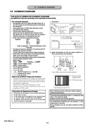
... Data. 3) Select page: 40, address: 38, and set data: 00. 4) Click [Save] on the camera. PRECAUTION ON REPLACING THE SY-176 BOARD VIDEO OUT Default Data Check When you replace to the repairing board, the written data of repairing board also might be changed. Accordingly, change the following data so as to English... Portuguese Simplified Chinese Russian Korean GP2 z z z GP3 z z z z GP4 z z z z z Note: GP2 is either English, Spanish, or Russian. When the data has changed to the right value. DSC-W55_L2 1-3E 1-4. Initial Language Data Check If the SY-176 board was reset.
... Data. 3) Select page: 40, address: 38, and set data: 00. 4) Click [Save] on the camera. PRECAUTION ON REPLACING THE SY-176 BOARD VIDEO OUT Default Data Check When you replace to the repairing board, the written data of repairing board also might be changed. Accordingly, change the following data so as to English... Portuguese Simplified Chinese Russian Korean GP2 z z z GP3 z z z z GP4 z z z z z Note: GP2 is either English, Spanish, or Russian. When the data has changed to the right value. DSC-W55_L2 1-3E 1-4. Initial Language Data Check If the SY-176 board was reset.

Service Manual
Page 8
... that the flat cable and flexible board are not cracked of bent at wire of 1 kΩ /1 W (1-215-869-11). R:1 kΩ/1 W (Part code: 1-215-869-11) DSC-W55_L2 2-1 The electric shock is caused by this high voltage when the capacitor is snapped. • Do not apply excessive load to each end of... short jig about 10 seconds. Do not insert the cable insufficiently nor crookedly. • When remove a connector, dont' pull at the terminal. DISASSEMBLY NOTE FOR REPAIR • Make sure that a wire is attached to the gilded flexible board.
... that the flat cable and flexible board are not cracked of bent at wire of 1 kΩ /1 W (1-215-869-11). R:1 kΩ/1 W (Part code: 1-215-869-11) DSC-W55_L2 2-1 The electric shock is caused by this high voltage when the capacitor is snapped. • Do not apply excessive load to each end of... short jig about 10 seconds. Do not insert the cable insufficiently nor crookedly. • When remove a connector, dont' pull at the terminal. DISASSEMBLY NOTE FOR REPAIR • Make sure that a wire is attached to the gilded flexible board.
Service Manual
Page 26
... each block) (For schematic diagrams) • All capacitors are 1/10 W unless otherwise noted. DSC-W55_L2 4-3 kΩ=1000 Ω, MΩ=1000 kΩ. • Caution when replacing chip parts...the imager has been replaced, carry out all the adjustments for repair. • A: not use circuit (Measuring conditions voltage and waveform) • Voltages and ...careful not to the model/destination. 4-2. b can be attached after removal of the lens L Camera 2. SCHEMATIC DIAGRAMS 4-2. Connection Pattern box Color bar chart Pattern box PTB-450 J-6082-200-A or...
... each block) (For schematic diagrams) • All capacitors are 1/10 W unless otherwise noted. DSC-W55_L2 4-3 kΩ=1000 Ω, MΩ=1000 kΩ. • Caution when replacing chip parts...the imager has been replaced, carry out all the adjustments for repair. • A: not use circuit (Measuring conditions voltage and waveform) • Voltages and ...careful not to the model/destination. 4-2. b can be attached after removal of the lens L Camera 2. SCHEMATIC DIAGRAMS 4-2. Connection Pattern box Color bar chart Pattern box PTB-450 J-6082-200-A or...

Service Manual
Page 41
REPAIR PARTS LIST NOTE: Characters A to Z of the electrical parts list indicate location of exploded views in which the desired part is shown. Link EXPLODED VIEWS A CABINET BLOCK B LCD BLOCK C LENS BLOCK D BT HOLDER BLOCK Link ELECTRICAL PARTS LIST ACCESSORIES CD-604 FLEXIBLE BOARD C MC-181 FLEXIBLE BOARD D RL-074 FLEXIBLE BOARD B ST-133 BOARD C ST-134 FLEXIBLE BOARD C SW-498 BOARD B DSC-W55_L2 NOTE 5.
REPAIR PARTS LIST NOTE: Characters A to Z of the electrical parts list indicate location of exploded views in which the desired part is shown. Link EXPLODED VIEWS A CABINET BLOCK B LCD BLOCK C LENS BLOCK D BT HOLDER BLOCK Link ELECTRICAL PARTS LIST ACCESSORIES CD-604 FLEXIBLE BOARD C MC-181 FLEXIBLE BOARD D RL-074 FLEXIBLE BOARD B ST-133 BOARD C ST-134 FLEXIBLE BOARD C SW-498 BOARD B DSC-W55_L2 NOTE 5.

Service Manual
Page 42
... : Korea model NE : North European model TW : Taiwan model When indicating parts by mark 0 or dotted line with mark 0 are seldom required for routine service. REPAIR PARTS LIST NOTE: • -XX, -X mean standardized parts, so they may have some differences from the parts specified in the diagrams or the components used... CND GP2 zz zz z AUS Vietnam AEP GP3 UK zzzzzz E AR BR TW GP4 JE z z zz HK CH KR MY z zzz z zz z zzz z z zz zz z DSC-W55_L2 5-1 Some delay should be anticipated when ordering these items. • The mechanical parts with part number specified...
... : Korea model NE : North European model TW : Taiwan model When indicating parts by mark 0 or dotted line with mark 0 are seldom required for routine service. REPAIR PARTS LIST NOTE: • -XX, -X mean standardized parts, so they may have some differences from the parts specified in the diagrams or the components used... CND GP2 zz zz z AUS Vietnam AEP GP3 UK zzzzzz E AR BR TW GP4 JE z z zz HK CH KR MY z zzz z zz z zzz z z zz zz z DSC-W55_L2 5-1 Some delay should be anticipated when ordering these items. • The mechanical parts with part number specified...

Service Manual
Page 43
Ver. 1.2 2007.06 5-1. No. 1 1 1 1 2 Part No. No. 4 5 6 7 *8 Part No. CABINET BLOCK 5. REPAIR PARTS LIST DISASSEMBLY HARDWARE LIST 2 #20 8 7 #20 1 #20 6 5 4 #20 #20 9 3 LCD Block (See page 5-3.) Ref. Description X-2176-619-1 CABINET (REAR) ASSY (240) (PINK) ... LID (PLATE), DC 3-093-810-01 LABEL, FUSE RATING 9 3-100-146-01 SPACER (240), MOARE #20 2-635-591-31 SCREW(M1.4),NEW TRUSTAR P2 (Silver) DSC-W55_L2 5-2 EXPLODED VIEWS 5-1-1. Description X-2176-553-1 CABINET (FRONT) ASSY (240) (SILVER) X-2176-614-1 CABINET(FRONT) ASSY(240) (BLACK) X-2176-615-1 CABINET(FRONT) ASSY(...
Ver. 1.2 2007.06 5-1. No. 1 1 1 1 2 Part No. No. 4 5 6 7 *8 Part No. CABINET BLOCK 5. REPAIR PARTS LIST DISASSEMBLY HARDWARE LIST 2 #20 8 7 #20 1 #20 6 5 4 #20 #20 9 3 LCD Block (See page 5-3.) Ref. Description X-2176-619-1 CABINET (REAR) ASSY (240) (PINK) ... LID (PLATE), DC 3-093-810-01 LABEL, FUSE RATING 9 3-100-146-01 SPACER (240), MOARE #20 2-635-591-31 SCREW(M1.4),NEW TRUSTAR P2 (Silver) DSC-W55_L2 5-2 EXPLODED VIEWS 5-1-1. Description X-2176-553-1 CABINET (FRONT) ASSY (240) (SILVER) X-2176-614-1 CABINET(FRONT) ASSY(240) (BLACK) X-2176-615-1 CABINET(FRONT) ASSY(...

Service Manual
Page 44
...3-941-343-21 TAPE (A) 0 BT001 1-756-711-11 LITHIUM RECHARGEABLE BATTERY LCD901 8-753-282-44 ACX358AKQ-3 #5 3-080-204-01 SCREW, TAPPING, P2 (Black) DSC-W55_L2 5-3 Description A-1231-199-A SW-498 BOARD, COMPLETE 2-895-948-01 DIAL (230), MODE A-1246-250-A CABINET UPPER(240),BLOCK ASSY (including RL-074 flexible...board) 3-100-145-01 CUSHION (240), MOARE 3-100-144-01 SHEET (240), MOARE 3-097-910-01 GASKET (240) Ref. Ver. 1.2 2007.06 5-1-2. REPAIR PARTS LIST DISASSEMBLY HARDWARE LIST #5 53 (including RL-074 flexible board) LCD901 54 51 52 BT001 SW-498 ns 57 55 58 Lens Block ! : BT001...
...3-941-343-21 TAPE (A) 0 BT001 1-756-711-11 LITHIUM RECHARGEABLE BATTERY LCD901 8-753-282-44 ACX358AKQ-3 #5 3-080-204-01 SCREW, TAPPING, P2 (Black) DSC-W55_L2 5-3 Description A-1231-199-A SW-498 BOARD, COMPLETE 2-895-948-01 DIAL (230), MODE A-1246-250-A CABINET UPPER(240),BLOCK ASSY (including RL-074 flexible...board) 3-100-145-01 CUSHION (240), MOARE 3-100-144-01 SHEET (240), MOARE 3-097-910-01 GASKET (240) Ref. Ver. 1.2 2007.06 5-1-2. REPAIR PARTS LIST DISASSEMBLY HARDWARE LIST #5 53 (including RL-074 flexible board) LCD901 54 51 52 BT001 SW-498 ns 57 55 58 Lens Block ! : BT001...
Service Manual
Page 45
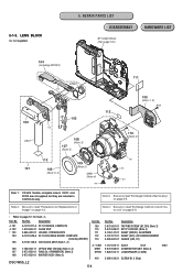
Note 4: Be sure to read "Precautions for mark 0. REPAIR PARTS LIST DISASSEMBLY BT holder Block (See page 5-5.) HARDWARE LIST 104 (including MIC901) ST-134 ns SP901 ST-133 102 ns C901 103 107 (Note 3) ... 1-788-363-11 OPTICS UNIT (ED13A) (Note 3, 4) 0* C901 M901 107 2-673-650-01 RING (A), ORNAMENTAL (Note 3) SP901 108 2-673-652-01 BARRIER ASSY (Note 3) #19 DSC-W55_L2 5-4 Part No. LENS BLOCK ns: not supplied 5. Part No. Note 2: Be sure to read "Exchange method of barrier assy" on page 2-9. • Refer to...
Note 4: Be sure to read "Precautions for mark 0. REPAIR PARTS LIST DISASSEMBLY BT holder Block (See page 5-5.) HARDWARE LIST 104 (including MIC901) ST-134 ns SP901 ST-133 102 ns C901 103 107 (Note 3) ... 1-788-363-11 OPTICS UNIT (ED13A) (Note 3, 4) 0* C901 M901 107 2-673-650-01 RING (A), ORNAMENTAL (Note 3) SP901 108 2-673-652-01 BARRIER ASSY (Note 3) #19 DSC-W55_L2 5-4 Part No. LENS BLOCK ns: not supplied 5. Part No. Note 2: Be sure to read "Exchange method of barrier assy" on page 2-9. • Refer to...

Service Manual
Page 46
...(240) (PINK) Note 3: BH001 is not supplied, but this is included in BT holder assy (240). BT HOLDER BLOCK" on page 2-5. * Refer to read "2-1-4. Ref. REPAIR PARTS LIST DISASSEMBLY HARDWARE LIST 162 #20 156 160 BH001 (Note 3) 161 (Note 2) ns ns ns 155 162 ns 159 #20 ns SY-176 #5 158...Note 3) CN001 (Not supplied) CONNECTOR, MULTIPLE (SOCKET) (Note 1) #5 3-080-204-01 SCREW, TAPPING, P2 (Black) #20 2-635-591-31 SCREW(M1.4),NEW TRUSTAR P2 (Silver) DSC-W55_L2 5-5 Ref. No. 157 158 * 159 160 Part No. BT HOLDER BLOCK ns: not supplied 5. Ver. 1.2 2007.06 5-1-4.
...(240) (PINK) Note 3: BH001 is not supplied, but this is included in BT holder assy (240). BT HOLDER BLOCK" on page 2-5. * Refer to read "2-1-4. Ref. REPAIR PARTS LIST DISASSEMBLY HARDWARE LIST 162 #20 156 160 BH001 (Note 3) 161 (Note 2) ns ns ns 155 162 ns 159 #20 ns SY-176 #5 158...Note 3) CN001 (Not supplied) CONNECTOR, MULTIPLE (SOCKET) (Note 1) #5 3-080-204-01 SCREW, TAPPING, P2 (Black) #20 2-635-591-31 SCREW(M1.4),NEW TRUSTAR P2 (Silver) DSC-W55_L2 5-5 Ref. No. 157 158 * 159 160 Part No. BT HOLDER BLOCK ns: not supplied 5. Ver. 1.2 2007.06 5-1-4.
Service Manual
Page 55
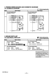
...Ref. Part No. Part No. Description 0* D002 6-501-141-01 DIODE FT02P80TP The components identified by mark 0 or dotted line with part number specified. DSC-W55_L2 - 2 - No. Part No. 4. Les composants identifiés par une marque 0 sont critiques pour la sécurité. SCHEMATIC DIAGRAMS :...Flexible Board Ref. PRINTED WIRING BOARDS AND SCHEMATIC DIAGRAMS 4-2. Part No. No. Replace only with mark 0 are critical for safety. No. REPAIR PARTS LIST 5-2. Ne les remplacer que par une pièce portant le numéro spécifié. No. ELECTRICAL PARTS ...
...Ref. Part No. Part No. Description 0* D002 6-501-141-01 DIODE FT02P80TP The components identified by mark 0 or dotted line with part number specified. DSC-W55_L2 - 2 - No. Part No. 4. Les composants identifiés par une marque 0 sont critiques pour la sécurité. SCHEMATIC DIAGRAMS :...Flexible Board Ref. PRINTED WIRING BOARDS AND SCHEMATIC DIAGRAMS 4-2. Part No. No. Replace only with mark 0 are critical for safety. No. REPAIR PARTS LIST 5-2. Ne les remplacer que par une pièce portant le numéro spécifié. No. ELECTRICAL PARTS ...

Service Manual
Page 60
Revised : Page 5-11 DSC-W55_L2 S.M. Correction :Page 3-1, 3-2, 3-3, 4-13, 4-19, 4-20, 4-21, 5-2, 5-3, 5-5, 5-6, 5-7, 5-11 1.3 2007.07 Supplement-1 • ST-133 Board Modification (Suffix -12 to No (DI07-033) -13) 1.4 2007.... (Suffix -11 to -21) • Change of Schematic Diagrams • Change of Electrical Parts List • Revision of Repair Parts. issued 1.0 2007.01 Official Release - - 1.1 2007.03 Revised-1 • Addition of Repair Parts, HELP Yes 1.2 2007.06 Revised-2 • Addition and Correction of Notes for the Yes Printed Wiring Boards and...
Revised : Page 5-11 DSC-W55_L2 S.M. Correction :Page 3-1, 3-2, 3-3, 4-13, 4-19, 4-20, 4-21, 5-2, 5-3, 5-5, 5-6, 5-7, 5-11 1.3 2007.07 Supplement-1 • ST-133 Board Modification (Suffix -12 to No (DI07-033) -13) 1.4 2007.... (Suffix -11 to -21) • Change of Schematic Diagrams • Change of Electrical Parts List • Revision of Repair Parts. issued 1.0 2007.01 Official Release - - 1.1 2007.03 Revised-1 • Addition of Repair Parts, HELP Yes 1.2 2007.06 Revised-2 • Addition and Correction of Notes for the Yes Printed Wiring Boards and...


