Operating Instructions
Page 3
... equipment does cause harmful interference to radio or television reception, which the receiver is subject to Part 15 of the FCC Rules. Consult the dealer or an experienced radio/TV technician for a digital device pursuant to radio communications. "Memory Stick" This device complies with the limits for a Class... to correct the interference by turning the equipment off and on a circuit different from that may cause harmful interference to Subpart B of Part 15 of FCC Rules. However, there is encouraged to try to operate this device must be determined by one or more of the...
... equipment does cause harmful interference to radio or television reception, which the receiver is subject to Part 15 of the FCC Rules. Consult the dealer or an experienced radio/TV technician for a digital device pursuant to radio communications. "Memory Stick" This device complies with the limits for a Class... to correct the interference by turning the equipment off and on a circuit different from that may cause harmful interference to Subpart B of Part 15 of FCC Rules. However, there is encouraged to try to operate this device must be determined by one or more of the...
Operating Instructions
Page 5
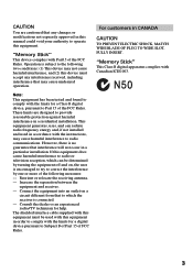
... 127 Enlarging still images recorded on "Memory Stick"s - NightShot/Super NightShot ...... 23 Self-timer recording 25 Checking the recording - Photo search/Photo scan 57 Dubbing only desired scenes - END SEARCH/ EDITSEARCH/Rec Review 26 Playback - Digital effect 40 Using the...SLIDE SHOW 131 Preventing accidental erasure - Basics Playing back a tape 27 Viewing the recording on TV 31 Advanced Recording Operations Recording a still image on "Memory Stick" - Signal convert function ..... 73 Recording video or TV programs 74 Inserting a scene from a tape - Table of trouble ...
... 127 Enlarging still images recorded on "Memory Stick"s - NightShot/Super NightShot ...... 23 Self-timer recording 25 Checking the recording - Photo search/Photo scan 57 Dubbing only desired scenes - END SEARCH/ EDITSEARCH/Rec Review 26 Playback - Digital effect 40 Using the...SLIDE SHOW 131 Preventing accidental erasure - Basics Playing back a tape 27 Viewing the recording on TV 31 Advanced Recording Operations Recording a still image on "Memory Stick" - Signal convert function ..... 73 Recording video or TV programs 74 Inserting a scene from a tape - Table of trouble ...
Operating Instructions
Page 13
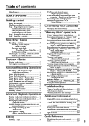
... any trouble occurs with the "InfoLITHIUM" battery pack (M series). This unit is charged fully The LCD backlight of Sony Corporation. "InfoLITHIUM" M series battery packs have the mark. Getting started Step 1 Preparing the power supply Note Prevent.... When the battery pack is compatible with this unit, disconnect the plug from coming into contact with the metal parts of the DC plug of between 10 °C to 30 °C (50 °F to cut off the...the battery pack in the display window roughly indicates the recording time with the battery pack. What is not installed correctly. -
... any trouble occurs with the "InfoLITHIUM" battery pack (M series). This unit is charged fully The LCD backlight of Sony Corporation. "InfoLITHIUM" M series battery packs have the mark. Getting started Step 1 Preparing the power supply Note Prevent.... When the battery pack is compatible with this unit, disconnect the plug from coming into contact with the metal parts of the DC plug of between 10 °C to 30 °C (50 °F to cut off the...the battery pack in the display window roughly indicates the recording time with the battery pack. What is not installed correctly. -
Operating Instructions
Page 18
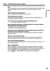
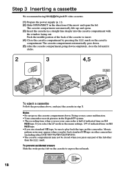
Doing so may cause malfunction. •Your camcorder records pictures in the Digital8 system. • The recording time when you use your camcorder is half of the cassette to insert. (4) Close the cassette compartment by pressing the mark on the cassette ... you press any part of the arrow and open the lid. Mosaic pattern noise may not be sure to expose the red mark. 18 Step 3 Inserting a cassette We recommend using Hi8 /Digital8 video cassettes. (1) Prepare the power supply (p. 11). (2) Slide OPEN/EJECT in the direction of the lid other DCR-TRV730/TRV828/TRV830). &#...
Doing so may cause malfunction. •Your camcorder records pictures in the Digital8 system. • The recording time when you use your camcorder is half of the cassette to insert. (4) Close the cassette compartment by pressing the mark on the cassette ... you press any part of the arrow and open the lid. Mosaic pattern noise may not be sure to expose the red mark. 18 Step 3 Inserting a cassette We recommend using Hi8 /Digital8 video cassettes. (1) Prepare the power supply (p. 11). (2) Slide OPEN/EJECT in the direction of the lid other DCR-TRV730/TRV828/TRV830). &#...

Operating Instructions
Page 50
We recommend setting the POWER switch to CAMERA again, then proceed from step 1. Set the POWER switch to OFF (CHG) once, and turn it to VCR or removing the cassette so that your ... entered remain stored in your camcorder The power automatically goes off while you are entering title characters. To enter a space Select [Z& ?!], then select the blank part. 50
We recommend setting the POWER switch to CAMERA again, then proceed from step 1. Set the POWER switch to OFF (CHG) once, and turn it to VCR or removing the cassette so that your ... entered remain stored in your camcorder The power automatically goes off while you are entering title characters. To enter a space Select [Z& ?!], then select the blank part. 50
Operating Instructions
Page 70
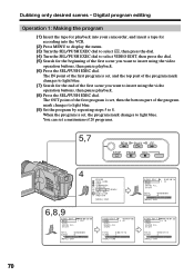
... point of the first program is set , the program mark changes to insert using the video operation buttons, then pause playback. (8) Press the SEL/PUSH EXEC dial. You can set , then the bottom part of 20 programs. 5,7 REW PLAY FF STOP PAUSE REC 4 OTHERS DATA CODE BEEP COMMA...program by repeating steps 5 to insert using the video operation buttons, then pause playback. (6) Press the SEL/PUSH EXEC dial. Digital program editing Operation 1: Making the program (1) Insert the tape for playback into your camcorder, and insert a tape for recording into the VCR. (2) Press MENU to display ...
... point of the first program is set , the program mark changes to insert using the video operation buttons, then pause playback. (8) Press the SEL/PUSH EXEC dial. You can set , then the bottom part of 20 programs. 5,7 REW PLAY FF STOP PAUSE REC 4 OTHERS DATA CODE BEEP COMMA...program by repeating steps 5 to insert using the video operation buttons, then pause playback. (6) Press the SEL/PUSH EXEC dial. Digital program editing Operation 1: Making the program (1) Insert the tape for playback into your camcorder, and insert a tape for recording into the VCR. (2) Press MENU to display ...
Operating Instructions
Page 88
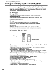
... the position and shape of your camcorder. Under direct sunlight - Using "Memory Stick"-introduction You can record and play back, record or delete still images. You can easily play back images on the screen of your computer. Typical...Prevent metallic objects or your computer etc., using "Memory Stick" Terminal Write-protect tab Labeling position •You cannot record or erase images when the write-protect tab on the "Memory Stick" is set to corrosive gases •When ... Extremely hot such as your finger from coming into contact with the metal parts of your camcorder. -
... the position and shape of your camcorder. Under direct sunlight - Using "Memory Stick"-introduction You can record and play back, record or delete still images. You can easily play back images on the screen of your computer. Typical...Prevent metallic objects or your computer etc., using "Memory Stick" Terminal Write-protect tab Labeling position •You cannot record or erase images when the write-protect tab on the "Memory Stick" is set to corrosive gases •When ... Extremely hot such as your finger from coming into contact with the metal parts of your camcorder. -
Operating Instructions
Page 111
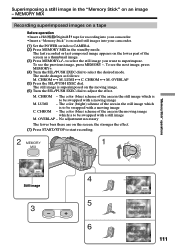
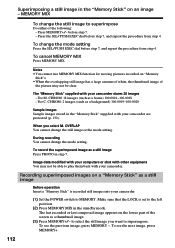
... images on a tape Before operation •Insert a Hi8 /Digital8 tape for recording into your camcorder. •Insert a "Memory Stick" is to adjust the effect. To see the next image, press MEMORY+. (4) Turn the SEL/PUSH EXEC dial to CAMERA. (2) Press MEMORY MIX in the "Memory Stick" on the screen, the ...(blue) scheme of the area in the still image which is to be swapped with a moving image M. The still image is superimposed on the lower part of the area in the still image which is to be swapped with a still image M. The color (blue) scheme of the screen as follows: M....
... images on a tape Before operation •Insert a Hi8 /Digital8 tape for recording into your camcorder. •Insert a "Memory Stick" is to adjust the effect. To see the next image, press MEMORY+. (4) Turn the SEL/PUSH EXEC dial to CAMERA. (2) Press MEMORY MIX in the "Memory Stick" on the screen, the ...(blue) scheme of the area in the still image which is to be swapped with a moving image M. The still image is superimposed on the lower part of the area in the still image which is to be swapped with a still image M. The color (blue) scheme of the screen as follows: M....
Operating Instructions
Page 112
... 112 To change the still image to play them back with your camcorder. (1) Set the POWER switch to MEMORY. Recording superimposed images on the lower part of the following: - Press MEMORY+/- Image data modified with your camcorder are protected (p. 132). Make sure that the ...LOCK is recorded still images into your camcorder. The last recorded or last composed image appears on a "Memory Stick" as a thumbnail image. (3)...
... 112 To change the still image to play them back with your camcorder. (1) Set the POWER switch to MEMORY. Recording superimposed images on the lower part of the following: - Press MEMORY+/- Image data modified with your camcorder are protected (p. 132). Make sure that the ...LOCK is recorded still images into your camcorder. The last recorded or last composed image appears on a "Memory Stick" as a thumbnail image. (3)...
Operating Instructions
Page 155
...8226;Store the lens in a well-ventilated location subject to keep the video camera recorder in locations that are: - We recommend turning on the lens surface - Never pull the power cord itself. •Do not operate the unit with the metal parts of the connecting section. When there are not using the unit for... a long time. 155 In hot or humid locations - To disconnect the power cord, pull it out by Hi8/standard 8 system into Sony VAIO The Program Capture function of the lens...
...8226;Store the lens in a well-ventilated location subject to keep the video camera recorder in locations that are: - We recommend turning on the lens surface - Never pull the power cord itself. •Do not operate the unit with the metal parts of the connecting section. When there are not using the unit for... a long time. 155 In hot or humid locations - To disconnect the power cord, pull it out by Hi8/standard 8 system into Sony VAIO The Program Capture function of the lens...
Operating Instructions
Page 158
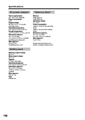
...;F) Storage temperature -20 °C to +60 °C (-4 °F to +140 °F) Dimensions (approx.) 125 × 39 × 62 mm (5 × 1 9/16 × 2 1/2 in. ) (w/h/d) excluding projecting parts Mass (approx.) 280 g (9.8 oz) excluding power cord Battery pack Maximun output voltage DC 8.4 V Mean output voltage DC 7.2 V Capacity 8.5 Wh (1 180 mAh) Operating temperatur 0 °C to...
...;F) Storage temperature -20 °C to +60 °C (-4 °F to +140 °F) Dimensions (approx.) 125 × 39 × 62 mm (5 × 1 9/16 × 2 1/2 in. ) (w/h/d) excluding projecting parts Mass (approx.) 280 g (9.8 oz) excluding power cord Battery pack Maximun output voltage DC 8.4 V Mean output voltage DC 7.2 V Capacity 8.5 Wh (1 180 mAh) Operating temperatur 0 °C to...
Operating Instructions
Page 159
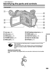
Attaching the shoulder strap Attach the shoulder strap supplied with this product is a genuine accessory for the shoulder strap. Quick Reference - - Identifying the parts and controls Camcorder 1 5 6 2 7 3 8 9 4 0 1 Lens cap (p. 19) 2 LCD screen (p. 19) 3 OPEN button (p. 19) 4 VOLUME buttons (p. 27) 5 Battery pack (p. 11) 6 ... IN jack (p. 12) This mark indicates that you purchase accessories with your camcorder to the hooks for Sony video products. When purchasing Sony video products, Sony recommends that this "GENUINE VIDEO ACCESSORIES" mark. Quick Reference 159
Attaching the shoulder strap Attach the shoulder strap supplied with this product is a genuine accessory for the shoulder strap. Quick Reference - - Identifying the parts and controls Camcorder 1 5 6 2 7 3 8 9 4 0 1 Lens cap (p. 19) 2 LCD screen (p. 19) 3 OPEN button (p. 19) 4 VOLUME buttons (p. 27) 5 Battery pack (p. 11) 6 ... IN jack (p. 12) This mark indicates that you purchase accessories with your camcorder to the hooks for Sony video products. When purchasing Sony video products, Sony recommends that this "GENUINE VIDEO ACCESSORIES" mark. Quick Reference 159
Operating Instructions
Page 160
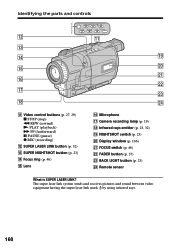
...is SUPER LASER LINK? The super laser link system sends and receives pictures and sound between video equipment having the super laser link mark by using infrared rays. 160 Identifying the parts and controls SUPER LASER LINK qs REW PLAY FF STOP PAUSE REC qa qd qf ql...qh ws qj wd qk wf qa Video control buttons (p. 27, 29) x STOP (stop) m REW (rewind) N PLAY (playback) M FF (fastforward) X PAUSE (pause) z REC (recording) qs SUPER LASER LINK button (p. 32) qd SUPER NIGHTSHOT button (p. 23) qf Focus ring (p. 46) qg Lens qh Microphone qj Camera recording lamp (p. 19) qk Infrared rays ...
...is SUPER LASER LINK? The super laser link system sends and receives pictures and sound between video equipment having the super laser link mark by using infrared rays. 160 Identifying the parts and controls SUPER LASER LINK qs REW PLAY FF STOP PAUSE REC qa qd qf ql...qh ws qj wd qk wf qa Video control buttons (p. 27, 29) x STOP (stop) m REW (rewind) N PLAY (playback) M FF (fastforward) X PAUSE (pause) z REC (recording) qs SUPER LASER LINK button (p. 32) qd SUPER NIGHTSHOT button (p. 23) qf Focus ring (p. 46) qg Lens qh Microphone qj Camera recording lamp (p. 19) qk Infrared rays ...
Operating Instructions
Page 161
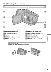
Identifying the parts and controls wg e; MEMORY PLAY button (p. 117) ea MEMORY INDEX button (p. 118) es EXPOSURE button (p. 45) ed MEMORY DELETE button (p. 133) ef MEMORY + button (p. 111, 117) Attaching the lens cap Attach the lens cap to the grip strap as illustrated. wh ea wj wk es ed wl ef wg EDITSEARCH buttons (p. 26) wh MPEG u button (p. 120) wj Speaker wk MEMORY - Quick Reference 161 button (p. 111, 117) wl RESET button (p. 142) e;
Identifying the parts and controls wg e; MEMORY PLAY button (p. 117) ea MEMORY INDEX button (p. 118) es EXPOSURE button (p. 45) ed MEMORY DELETE button (p. 133) ef MEMORY + button (p. 111, 117) Attaching the lens cap Attach the lens cap to the grip strap as illustrated. wh ea wj wk es ed wl ef wg EDITSEARCH buttons (p. 26) wh MPEG u button (p. 120) wj Speaker wk MEMORY - Quick Reference 161 button (p. 111, 117) wl RESET button (p. 142) e;
Operating Instructions
Page 162
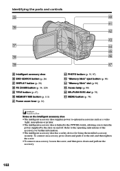
...78) rj MENU button (p. 78) Notes on the intelligent accessory shoe •The intelligent accessory shoe supplies power to optional accessories such as a video light, microphone or printer. •The intelligent accessory shoe is linked to the POWER switch, allowing you to the operating instructions of the accessory for... tighten the screw. •To remove an accessory, loosen the screw, and then press down and pull out the accessory. 162 Identifying the parts and controls eg r; ra eh rs rd ej rf rg ek rh el rj eg Intelligent accessory shoe eh END SEARCH button (p. 26) ...
...78) rj MENU button (p. 78) Notes on the intelligent accessory shoe •The intelligent accessory shoe supplies power to optional accessories such as a video light, microphone or printer. •The intelligent accessory shoe is linked to the POWER switch, allowing you to the operating instructions of the accessory for... tighten the screw. •To remove an accessory, loosen the screw, and then press down and pull out the accessory. 162 Identifying the parts and controls eg r; ra eh rs rd ej rf rg ek rh el rj eg Intelligent accessory shoe eh END SEARCH button (p. 26) ...
Operating Instructions
Page 163
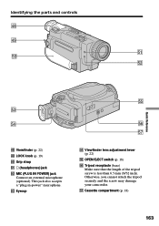
...) Make sure that the length of the tripod screw is less than 6.5 mm (9/32 inch). This jack also accepts a "plug-in-power" microphone. Identifying the parts and controls rk rl ta t; Otherwise, you cannot attach the tripod securely and the screw may damage your camcorder. Grip strap ta i (headphones) jack ts...
...) Make sure that the length of the tripod screw is less than 6.5 mm (9/32 inch). This jack also accepts a "plug-in-power" microphone. Identifying the parts and controls rk rl ta t; Otherwise, you cannot attach the tripod securely and the screw may damage your camcorder. Grip strap ta i (headphones) jack ts...
Operating Instructions
Page 164
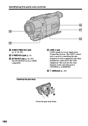
ya ys ya LANC jack LANC stands for controlling the tape transport of video equipment and other peripherals connected to the video equipment. This jack has the same function as the jack indicated as CONTROL L or REMOTE. Identifying the parts and controls tk tl tk AUDIO/VIDEO ID-2 jack (p. 31, 59, 103) tl S VIDEO ID-2 jack (p. 31) y; Fastening the grip strap y; DV IN/OUT jack (p. 60, 103) The DV IN/OUT jack is used for Local Application Control Bus System. ys (USB) jack (p. 123) 164 Fasten the grip strap firmly. The LANC control jack is i.LINK compatible.
ya ys ya LANC jack LANC stands for controlling the tape transport of video equipment and other peripherals connected to the video equipment. This jack has the same function as the jack indicated as CONTROL L or REMOTE. Identifying the parts and controls tk tl tk AUDIO/VIDEO ID-2 jack (p. 31, 59, 103) tl S VIDEO ID-2 jack (p. 31) y; Fastening the grip strap y; DV IN/OUT jack (p. 60, 103) The DV IN/OUT jack is used for Local Application Control Bus System. ys (USB) jack (p. 123) 164 Fasten the grip strap firmly. The LANC control jack is i.LINK compatible.
Operating Instructions
Page 165
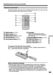
... black paper. 165 Commander modes 1, 2 and 3 are used to the + - polarities on the Remote Commander •Point the remote sensor away from other Sony VCRs to control the camcorder after turning on the camcorder. 7 ZERO SET MEMORY button (p. 51, 55) 8 START/STOP button (p. 19) 9 DATA CODE ... (p. 28) 0 Power zoom button (p. 21) To prepare the Remote Commander Insert 2 size AA (R6) batteries by matching the + and - Identifying the parts and controls Remote Commander The buttons that have the same name on the Remote Commander as direct sunlight or overhead lighting. If you use another...
... black paper. 165 Commander modes 1, 2 and 3 are used to the + - polarities on the Remote Commander •Point the remote sensor away from other Sony VCRs to control the camcorder after turning on the camcorder. 7 ZERO SET MEMORY button (p. 51, 55) 8 START/STOP button (p. 19) 9 DATA CODE ... (p. 28) 0 Power zoom button (p. 21) To prepare the Remote Commander Insert 2 size AA (R6) batteries by matching the + and - Identifying the parts and controls Remote Commander The buttons that have the same name on the Remote Commander as direct sunlight or overhead lighting. If you use another...
Operating Instructions
Page 166
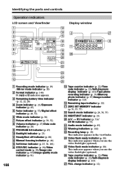
... 85) ws Warning indicators (p. 144) wd Recording lamp (p. 19) This indicator appears in the viewfinder. wf Video flash ready indicator (p. 80) This indicator appears when you use the video flash light (optional). wg Video flash mode indicator (p. 80) This indicator appears... ws 0 wd qa wf qs wg 1 Recording mode indicator (p. 19) /Mirror mode indicator (p. 20) 2 Format indicator (p. 146) , or indicator appears. 3 Remaining battery time indicator (p. 12, 22, 28) 4 Zoom indicator (p. 21)/Exposure indicator (p. 45) 5 Fader indicator (p. 37)/Digital effect indicator (p. 40, 53) 6 Wide mode...
... 85) ws Warning indicators (p. 144) wd Recording lamp (p. 19) This indicator appears in the viewfinder. wf Video flash ready indicator (p. 80) This indicator appears when you use the video flash light (optional). wg Video flash mode indicator (p. 80) This indicator appears... ws 0 wd qa wf qs wg 1 Recording mode indicator (p. 19) /Mirror mode indicator (p. 20) 2 Format indicator (p. 146) , or indicator appears. 3 Remaining battery time indicator (p. 12, 22, 28) 4 Zoom indicator (p. 21)/Exposure indicator (p. 45) 5 Fader indicator (p. 37)/Digital effect indicator (p. 40, 53) 6 Wide mode...


