Operating Instructions
Page 3
... the separation between the equipment and receiver. - Consult the dealer or an experienced radio/TV technician for a Class B digital device, pursuant to Part 15 of the FCC Rules. For customers in a particular installation. Operation is no guarantee that to provide reasonable protection against... harmful interference in CANADA This Class B digital apparatus complies with the instructions, may not cause harmful interference, and (2) ...
... the separation between the equipment and receiver. - Consult the dealer or an experienced radio/TV technician for a Class B digital device, pursuant to Part 15 of the FCC Rules. For customers in a particular installation. Operation is no guarantee that to provide reasonable protection against... harmful interference in CANADA This Class B digital apparatus complies with the instructions, may not cause harmful interference, and (2) ...
Operating Instructions
Page 5
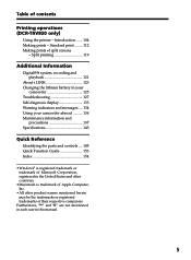
... their respective companies. Introduction ....... 104 Making prints - Split printing 119 Additional Information Digital8 system, recording and playback 121 About i.LINK 123 Changing the lithium battery in your camcorder 125 Troubleshooting 127 Self...134 Using your camcorder abroad .......... 136 Maintenance information and precautions 137 Specifications 143 Quick Reference Identifying the parts and controls .... 145 Quick Function Guide 153 Index 154 • Windows® is trademark of... ........ 112 Making prints of contents Printing operations (DCR-TRV820 only) Using the printer -
... their respective companies. Introduction ....... 104 Making prints - Split printing 119 Additional Information Digital8 system, recording and playback 121 About i.LINK 123 Changing the lithium battery in your camcorder 125 Troubleshooting 127 Self...134 Using your camcorder abroad .......... 136 Maintenance information and precautions 137 Specifications 143 Quick Reference Identifying the parts and controls .... 145 Quick Function Guide 153 Index 154 • Windows® is trademark of... ........ 112 Making prints of contents Printing operations (DCR-TRV820 only) Using the printer -
Operating Instructions
Page 12
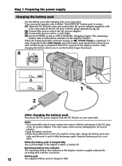
... battery longer than usual. 4 VTR OFF (CHARGE) MEMORY CAMERA 1 2 After charging the battery pack Disconnect the AC power adaptor from coming into contact with the metal parts of the DC plug of the display window is indicated in the display window roughly indicates the recording time with the plug's v mark facing up. (2) Connect...
... battery longer than usual. 4 VTR OFF (CHARGE) MEMORY CAMERA 1 2 After charging the battery pack Disconnect the AC power adaptor from coming into contact with the metal parts of the DC plug of the display window is indicated in the display window roughly indicates the recording time with the plug's v mark facing up. (2) Connect...
Operating Instructions
Page 16
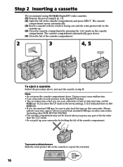
... other DCR-TRV720/TRV820). •The cassette compartment may not be sure to expose the red mark. 16 Mosaic pattern noise may cause malfunction. •Your camcorder records pictures in... the procedure above, and eject the cassette in the Digital8 system. • The recording time when you press any part of the lid other than the mark. •Do not pick up . (4) Close...of the cassette compartment, and press EJECT. Step 2 Inserting a cassette We recommend using Hi8 /Digital8 video cassettes. (1) Prepare the power supply (p. 11). (2) Open the lid of indicated time on Hi8...
... other DCR-TRV720/TRV820). •The cassette compartment may not be sure to expose the red mark. 16 Mosaic pattern noise may cause malfunction. •Your camcorder records pictures in... the procedure above, and eject the cassette in the Digital8 system. • The recording time when you press any part of the lid other than the mark. •Do not pick up . (4) Close...of the cassette compartment, and press EJECT. Step 2 Inserting a cassette We recommend using Hi8 /Digital8 video cassettes. (1) Prepare the power supply (p. 11). (2) Open the lid of indicated time on Hi8...

Operating Instructions
Page 48
... which title you want to delete the title. To enter a space Select [Z& ?!], then select the blank part. 48 The last character is erased. If you are entering title characters. Select [ to the previous screen. ] to CAMERA again, then proceed from step 1. We recommend setting the POWER switch to VTR or removing the...
... which title you want to delete the title. To enter a space Select [Z& ?!], then select the blank part. 48 The last character is erased. If you are entering title characters. Select [ to the previous screen. ] to CAMERA again, then proceed from step 1. We recommend setting the POWER switch to VTR or removing the...

Operating Instructions
Page 74
...or keep "Memory Stick"s in the following cases: - - You can exchange image data with your finger from coming into contact with the metal parts of the connecting section. •Stick its case. 74 If you remove the "Memory Stick", turn the power off, or detach the battery ...under the scorching sun - Extremely hot such as a personal computer etc., using "Memory Stick" Terminal Write-protect tab Labeling position •You cannot record or erase still images when the write-protect tab on the "Memory Stick" is flashing - Under direct sunlight - Very humid or subject to LOCK...
...or keep "Memory Stick"s in the following cases: - - You can exchange image data with your finger from coming into contact with the metal parts of the connecting section. •Stick its case. 74 If you remove the "Memory Stick", turn the power off, or detach the battery ...under the scorching sun - Extremely hot such as a personal computer etc., using "Memory Stick" Terminal Write-protect tab Labeling position •You cannot record or erase still images when the write-protect tab on the "Memory Stick" is flashing - Under direct sunlight - Very humid or subject to LOCK...

Operating Instructions
Page 85
...screen, the stronger the effect. (7) Press START/STOP to start recording. 2 1 MEMORY MIX VTR "Memory Stick" operations OFF (CHARGE) MEMORY CAMERA M. MEMORY MIX Before operation Insert a Hi8 /Digital8 tape for recording and a "Memory Stick" into your camcorder. (1) Set the ...M. Superimposing a still image in the "Memory Stick" on the lower part of the screen as follows: M. CHROM y M. CHROM y M. CHROM 100-0021 Still image 3 4 M. LUMI I I I 100-0021 85 CHROM - LUMI 5 100-0021 M. The last recorded still image on "Memory Stick" appears on a moving image M. LUMI...
...screen, the stronger the effect. (7) Press START/STOP to start recording. 2 1 MEMORY MIX VTR "Memory Stick" operations OFF (CHARGE) MEMORY CAMERA M. MEMORY MIX Before operation Insert a Hi8 /Digital8 tape for recording and a "Memory Stick" into your camcorder. (1) Set the ...M. Superimposing a still image in the "Memory Stick" on the lower part of the screen as follows: M. CHROM y M. CHROM y M. CHROM 100-0021 Still image 3 4 M. LUMI I I I 100-0021 85 CHROM - LUMI 5 100-0021 M. The last recorded still image on "Memory Stick" appears on a moving image M. LUMI...

Operating Instructions
Page 109
... the print surface is protruding from your camcorder. Insert the print paper until less than 3 cm Printing operations 109 Press the print paper into the part of the arrow to open.
... the print surface is protruding from your camcorder. Insert the print paper until less than 3 cm Printing operations 109 Press the print paper into the part of the arrow to open.
Operating Instructions
Page 118
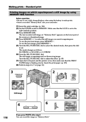
...100-0021 5 Still image 4 6 118 If you want to 7 on page 112. 3 2 MEMORY MIX VTR OFF (CHARGE) MEMORY CAMERA M. LUMI 100-0021 M. The last recorded still image on "Memory Stick" appears on the moving image. To see the previous image, press MEMORY -. The still image is flashing ...slowly. Insert the print paper. (p. 109) (8) Perform steps 4 to superimpose. Make sure that the PRINT PAPER lamp is superimposed on the lower part...
...100-0021 5 Still image 4 6 118 If you want to 7 on page 112. 3 2 MEMORY MIX VTR OFF (CHARGE) MEMORY CAMERA M. LUMI 100-0021 M. The last recorded still image on "Memory Stick" appears on the moving image. To see the previous image, press MEMORY -. The still image is flashing ...slowly. Insert the print paper. (p. 109) (8) Perform steps 4 to superimpose. Make sure that the PRINT PAPER lamp is superimposed on the lower part...
Operating Instructions
Page 140
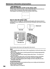
Cleaner part Front side Back side 140 Less than 3 times. • Because cleaning the...• Platen roller cleaner (1-772-862-11) If this happens, clean the platen roller with the platen roller cleaner. DCR-TRV820 only About the influence of printed image per platen roller cleaner. How to clean the platen roller Perform steps 1 ...by printing an image on the platen roller which it will be clear. On purchasing cleaners Contact your Sony dealer or local authorized Sony service facility and inform them of print paper in . Maintenance information and precautions - Note that the...
Cleaner part Front side Back side 140 Less than 3 times. • Because cleaning the...• Platen roller cleaner (1-772-862-11) If this happens, clean the platen roller with the platen roller cleaner. DCR-TRV820 only About the influence of printed image per platen roller cleaner. How to clean the platen roller Perform steps 1 ...by printing an image on the platen roller which it will be clear. On purchasing cleaners Contact your Sony dealer or local authorized Sony service facility and inform them of print paper in . Maintenance information and precautions - Note that the...

Operating Instructions
Page 142
... the unit may cause fire or electrical shock. •Prevent metallic objects from coming into your eyes, wash your nearest Sony dealer. 142 Note on it away from AM receivers and video equipment. Dry batteries are : - Do not use . Current flows from batteries when you are not using the unit ...new and old batteries. - To disconnect the power cord, pull it off with water. •If the liquid get into contact with the metal parts of water and then consult a doctor. Be sure to insert the batteries with the battery terminals. •Keep the battery pack away from fire. ...
... the unit may cause fire or electrical shock. •Prevent metallic objects from coming into your eyes, wash your nearest Sony dealer. 142 Note on it away from AM receivers and video equipment. Dry batteries are : - Do not use . Current flows from batteries when you are not using the unit ...new and old batteries. - To disconnect the power cord, pull it off with water. •If the liquid get into contact with the metal parts of water and then consult a doctor. Be sure to insert the batteries with the battery terminals. •Keep the battery pack away from fire. ...

Operating Instructions
Page 144
... (approx.) 0.14 oz (4 g) Design and specifications are subject to +60 °C) Dimensions (approx.) 5 × 1 9/16 × 2 1/2 in. (125 × 39 × 62 mm) (w/h/d) excluding projecting parts Mass (approx.) 9.8 oz (280 g) excluding power cord "Memory Stick" Memory Flash memory 4MB: MSA-4A Operating voltage 2.7 - 3.6 V Power consumption Approx. 45 mA in the operating...
... (approx.) 0.14 oz (4 g) Design and specifications are subject to +60 °C) Dimensions (approx.) 5 × 1 9/16 × 2 1/2 in. (125 × 39 × 62 mm) (w/h/d) excluding projecting parts Mass (approx.) 9.8 oz (280 g) excluding power cord "Memory Stick" Memory Flash memory 4MB: MSA-4A Operating voltage 2.7 - 3.6 V Power consumption Approx. 45 mA in the operating...

Operating Instructions
Page 145
Quick Reference 145 Identifying the parts and controls Camcorder VTR 4 OFF (CHARGE) MEMORY CAMERA 5 1 6 2 7 3 8 1 LCD BRIGHT buttons (p. 18) 2 OPEN button (p. 17) 3 VOLUME buttons (p. 25) 4 START/STOP button (p. 17) 5 POWER switch (p. 17) 6 BATT RELEASE lever (p. 11) 7 Hooks for shoulder strap (p. 147) 8 DC IN jack (p. 12) This mark indicates that you purchase accessories with this product is a genuine accessory for Sony video products. - Quick Reference - When purchasing Sony video products, Sony recommends that this "GENUINE VIDEO ACCESSORIES" mark.
Quick Reference 145 Identifying the parts and controls Camcorder VTR 4 OFF (CHARGE) MEMORY CAMERA 5 1 6 2 7 3 8 1 LCD BRIGHT buttons (p. 18) 2 OPEN button (p. 17) 3 VOLUME buttons (p. 25) 4 START/STOP button (p. 17) 5 POWER switch (p. 17) 6 BATT RELEASE lever (p. 11) 7 Hooks for shoulder strap (p. 147) 8 DC IN jack (p. 12) This mark indicates that you purchase accessories with this product is a genuine accessory for Sony video products. - Quick Reference - When purchasing Sony video products, Sony recommends that this "GENUINE VIDEO ACCESSORIES" mark.

Operating Instructions
Page 146
EDITSEARCH buttons (p. 24) qa S.LASER LINK button (p. 29) qs Focus ring (p. 44) qd Microphone qf Camera recording lamp (p. 17) qg Infrared rays emitter (p. 21, 29) qh SUPER NIGHTSHOT button (p. 21) qj NIGHTSHOT switch (p. 21) qk Display window (p. 152) ql FOCUS switch (p. 44) w; ... the screw may damage your camcorder. The super laser link system sends and receives pictures and sound between video equipment having the super laser link mark by using infrared rays. 146 q; Otherwise, you set the POWER switch to VTR. Identifying the parts and controls 9 0 qa qh qs qj qk qd ql qf w;
EDITSEARCH buttons (p. 24) qa S.LASER LINK button (p. 29) qs Focus ring (p. 44) qd Microphone qf Camera recording lamp (p. 17) qg Infrared rays emitter (p. 21, 29) qh SUPER NIGHTSHOT button (p. 21) qj NIGHTSHOT switch (p. 21) qk Display window (p. 152) ql FOCUS switch (p. 44) w; ... the screw may damage your camcorder. The super laser link system sends and receives pictures and sound between video equipment having the super laser link mark by using infrared rays. 146 q; Otherwise, you set the POWER switch to VTR. Identifying the parts and controls 9 0 qa qh qs qj qk qd ql qf w;

Operating Instructions
Page 147
Quick Reference 147 wg ea es ed wh ef wj ws Eyecup wd MEMORY PLAY button (p. 91) wf MEMORY - button (p. 85, 91) wg LCD screen (p. 18) wh Speaker wj (self-timer) button (p. 23, 31, 83) wk Viewfinder lens adjustment lever (p. 20) wl MEMORY DELETE button (p. 100) e; FADER button (p. 34) ea BACK LIGHT button (p. 21) es PROGRAM AE button (p. 41) ed EXPOSURE button (p. 43) ef MEMORY MIX button (p. 84) Attaching the shoulder strap Attach the shoulder strap supplied with your camcorder to the hooks for the shoulder strap. Identifying the parts and controls ws wk wd wf wl e;
Quick Reference 147 wg ea es ed wh ef wj ws Eyecup wd MEMORY PLAY button (p. 91) wf MEMORY - button (p. 85, 91) wg LCD screen (p. 18) wh Speaker wj (self-timer) button (p. 23, 31, 83) wk Viewfinder lens adjustment lever (p. 20) wl MEMORY DELETE button (p. 100) e; FADER button (p. 34) ea BACK LIGHT button (p. 21) es PROGRAM AE button (p. 41) ed EXPOSURE button (p. 43) ef MEMORY MIX button (p. 84) Attaching the shoulder strap Attach the shoulder strap supplied with your camcorder to the hooks for the shoulder strap. Identifying the parts and controls ws wk wd wf wl e;

Operating Instructions
Page 148
...ek PB ZOOM button (p. 52, 96) el TITLE button (p. 45) r; rs PHOTO button (p. 30, 79) rd DIGITAL EFFECT button (p. 39, 51) rf END SEARCH button (p. 24) rg PICTURE EFFECT button (p. 37, 50) rh MENU...button (p. 33, 65) rj SEL/PUSH EXEC dial (p. 33, 65) Notes on and off. Identifying the parts and controls eg r; Power Zoom lever (p. 19) ra "Memory Stick" lamp This lamp lights up while ... accessory shoe •The intelligent accessory shoe supplies power to optional accessories such as a video light or microphone. •The intelligent accessory shoe is in the "Memory Stick" compartment...
...ek PB ZOOM button (p. 52, 96) el TITLE button (p. 45) r; rs PHOTO button (p. 30, 79) rd DIGITAL EFFECT button (p. 39, 51) rf END SEARCH button (p. 24) rg PICTURE EFFECT button (p. 37, 50) rh MENU...button (p. 33, 65) rj SEL/PUSH EXEC dial (p. 33, 65) Notes on and off. Identifying the parts and controls eg r; Power Zoom lever (p. 19) ra "Memory Stick" lamp This lamp lights up while ... accessory shoe •The intelligent accessory shoe supplies power to optional accessories such as a video light or microphone. •The intelligent accessory shoe is in the "Memory Stick" compartment...

Operating Instructions
Page 149
... 76) ta LOCK knob (p. 77) ts Cassette compartment (p. 16) td Grip strap tf LANC /DIGITAL I/O jack (p. 93) LANC stands for controlling the tape transport of video equipment and other peripherals connected to the video equipment. tl DV IN/OUT jack (p. 59, 62, 88) The DV IN/OUT jack is used...Control Bus System. This jack also accepts a "plug-in-power" microphone. Identifying the parts and controls rk rl tg t; The LANC control jack is i.LINK compatible. tg S VIDEO ID-2 jack (p. 28) th i (headphones) jack tj AUDIO/VIDEO ID-2 jack (p. 28, 58, 88) tk MIC (PLUG IN POWER) jack Connect...
... 76) ta LOCK knob (p. 77) ts Cassette compartment (p. 16) td Grip strap tf LANC /DIGITAL I/O jack (p. 93) LANC stands for controlling the tape transport of video equipment and other peripherals connected to the video equipment. tl DV IN/OUT jack (p. 59, 62, 88) The DV IN/OUT jack is used...Control Bus System. This jack also accepts a "plug-in-power" microphone. Identifying the parts and controls rk rl tg t; The LANC control jack is i.LINK compatible. tg S VIDEO ID-2 jack (p. 28) th i (headphones) jack tj AUDIO/VIDEO ID-2 jack (p. 28, 58, 88) tk MIC (PLUG IN POWER) jack Connect...

Operating Instructions
Page 150
Identifying the parts and controls y; ya ys yf yg yh yj yk yl u; Viewfinder (p. 20) ya MEMORY INDEX button (p. 92) ys Lithium battery compartment (p. 126) yd MEMORY + button (p. 85, 91) yf PRINT lamp* (p. 105) yg PRINT PAPER lamp* (p. 105) yh PRINT CARTRIDGE lamp* (p. 105) yj PRINT button* (p. 105) yk Printer cover* (p. 109) yl Print cartridge lid* (p. 106) u; PRINT CARTRIDGE OPEN knob* (p. 106) * DCR-TRV820 only 150 yd y;
Identifying the parts and controls y; ya ys yf yg yh yj yk yl u; Viewfinder (p. 20) ya MEMORY INDEX button (p. 92) ys Lithium battery compartment (p. 126) yd MEMORY + button (p. 85, 91) yf PRINT lamp* (p. 105) yg PRINT PAPER lamp* (p. 105) yh PRINT CARTRIDGE lamp* (p. 105) yj PRINT button* (p. 105) yk Printer cover* (p. 109) yl Print cartridge lid* (p. 106) u; PRINT CARTRIDGE OPEN knob* (p. 106) * DCR-TRV820 only 150 yd y;
Operating Instructions
Page 151
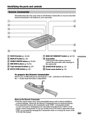
Identifying the parts and controls Remote Commander The buttons that have...to control the camcorder after turning on the Remote Commander •Point the remote sensor away from other Sony VCRs to avoid remote control misoperation. Otherwise, the Remote Commander may not function properly. •Your ... the Commander mode VTR 2, we recommend changing the Commander mode or covering the sensor of the VCR with black paper. 151 If you use another Sony VCR in the Commander mode VTR 2. Commander modes 1, 2 and 3 are used to distinguish your camcorder. 1 7 2 8 3 4 5 9 6 ...
Identifying the parts and controls Remote Commander The buttons that have...to control the camcorder after turning on the Remote Commander •Point the remote sensor away from other Sony VCRs to avoid remote control misoperation. Otherwise, the Remote Commander may not function properly. •Your ... the Commander mode VTR 2, we recommend changing the Commander mode or covering the sensor of the VCR with black paper. 151 If you use another Sony VCR in the Commander mode VTR 2. Commander modes 1, 2 and 3 are used to distinguish your camcorder. 1 7 2 8 3 4 5 9 6 ...
Operating Instructions
Page 152
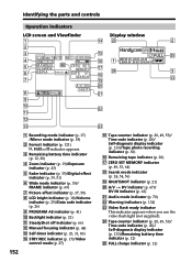
...video flash light (not supplied). Identifying the parts and controls Operation indicators LCD screen and Viewfinder Display window 1 qf ws 2 2 3 qg wg 4 40min SP REC 0:00:00 W T qh 1 5 M.FADER 16:9WIDE 6 SEPIA 7 ZERO SET MEMORY qj wf DATE 01 SEARCH qk ql 3 qd A / V DV w; 16BIT 8 wa 9 0 ws qa qs qd wd 1 Recording... mode indicator (p. 17) /Mirror mode indicator (p. 18) 2 Format indicator (p. 121) , or indicator appears. 3 Remaining battery time indicator (p. 12, 20) 4 Zoom indicator (p. 19)/Exposure indicator (p. 43) 5 Fader indicator (p. 35)/Digital...
...video flash light (not supplied). Identifying the parts and controls Operation indicators LCD screen and Viewfinder Display window 1 qf ws 2 2 3 qg wg 4 40min SP REC 0:00:00 W T qh 1 5 M.FADER 16:9WIDE 6 SEPIA 7 ZERO SET MEMORY qj wf DATE 01 SEARCH qk ql 3 qd A / V DV w; 16BIT 8 wa 9 0 ws qa qs qd wd 1 Recording... mode indicator (p. 17) /Mirror mode indicator (p. 18) 2 Format indicator (p. 121) , or indicator appears. 3 Remaining battery time indicator (p. 12, 20) 4 Zoom indicator (p. 19)/Exposure indicator (p. 43) 5 Fader indicator (p. 35)/Digital...


