Operating Instructions
Page 13
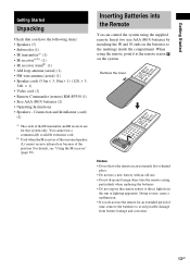
... Operating Instructions • Speakers - b) Used when the IR receiver of the surround speaker (L) cannot receive infrared ray because of the IR transmitter and IR receiver are for an extended period of time, remove the batteries to direct light from battery leakage and corrosion. 13US Remove the ...cover. Getting Started Getting Started Unpacking Check that you do not use the remote for this system only. Inserting Batteries into the remote casing, particularly when replacing the batteries. • Do not expose the remote sensor to avoid...
... Operating Instructions • Speakers - b) Used when the IR receiver of the surround speaker (L) cannot receive infrared ray because of the IR transmitter and IR receiver are for an extended period of time, remove the batteries to direct light from battery leakage and corrosion. 13US Remove the ...cover. Getting Started Getting Started Unpacking Check that you do not use the remote for this system only. Inserting Batteries into the remote casing, particularly when replacing the batteries. • Do not expose the remote sensor to avoid...
Operating Instructions
Page 14
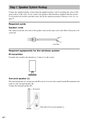
... ONLY FOR DIR-R2 Rear side of the jacks to be connected. (-) (-) (+) (+) color tube Required equipments for the wireless system IR transmitter Transmits the sound by matching the colors of the surround speaker (L) 14US To obtain the best possible surround sound, specify the speaker ...parameters (distance, level, etc.) on page 35. Step 1: Speaker System Hookup Connect the supplied speaker system using the supplied speaker cords by the infrared ray. It receives the sound from the IR transmitter and sends it to the surround speaker (R). Surround speaker (L) The surround speaker...
... ONLY FOR DIR-R2 Rear side of the jacks to be connected. (-) (-) (+) (+) color tube Required equipments for the wireless system IR transmitter Transmits the sound by matching the colors of the surround speaker (L) 14US To obtain the best possible surround sound, specify the speaker ...parameters (distance, level, etc.) on page 35. Step 1: Speaker System Hookup Connect the supplied speaker system using the supplied speaker cords by the infrared ray. It receives the sound from the IR transmitter and sends it to the surround speaker (R). Surround speaker (L) The surround speaker...
Operating Instructions
Page 16
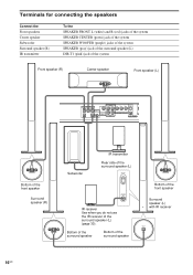
...) jack of the system Front speaker (R) Center speaker Front speaker (L) SPEAKER R FRONT R CENTER FRONT L DIR-T1 SURROUND BACK R WOOFER WOOFER VIDEO AUDIO IN AUDIO IN S AT Y L PB/CB PR/CR S VIDEO (DVD ONLY) O D COMPOMEMT VIDEO OUT L VIDEO MONITOR OUT Bottom of the front speaker Surround speaker (R) Subwoofer IR transmitter Rear side of the...
...) jack of the system Front speaker (R) Center speaker Front speaker (L) SPEAKER R FRONT R CENTER FRONT L DIR-T1 SURROUND BACK R WOOFER WOOFER VIDEO AUDIO IN AUDIO IN S AT Y L PB/CB PR/CR S VIDEO (DVD ONLY) O D COMPOMEMT VIDEO OUT L VIDEO MONITOR OUT Bottom of the front speaker Surround speaker (R) Subwoofer IR transmitter Rear side of the...
Operating Instructions
Page 17
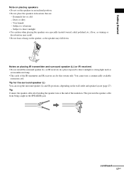
... as staining or discoloration may result. • Do not lean or hang on the wall outlet and speaker layout (page 27). Notes on placing IR transmitter and surround speaker (L) (or IR receiver) • Do not install the surround speaker (L) (or IR receiver) in a place exposed to vibrations -... 17US Tip Connect the speaker cable after bending the speaker wire at the end of the IR transmitter and IR receiver are : - You cannot use a commercially available extension cord. Tip for this system only. Getting Started Note on placing speakers • Do not set the speakers in an inclined...
... as staining or discoloration may result. • Do not lean or hang on the wall outlet and speaker layout (page 27). Notes on placing IR transmitter and surround speaker (L) (or IR receiver) • Do not install the surround speaker (L) (or IR receiver) in a place exposed to vibrations -... 17US Tip Connect the speaker cable after bending the speaker wire at the end of the IR transmitter and IR receiver are : - You cannot use a commercially available extension cord. Tip for this system only. Getting Started Note on placing speakers • Do not set the speakers in an inclined...
Operating Instructions
Page 20
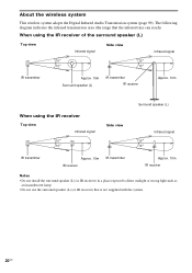
... wireless system This wireless system adopts the Digital Infrared Audio Transmission system (page 99). The following diagram indicates the infrared transmission area (the range that the infrared rays can reach) When using the IR receiver of the surround speaker (L) Top view Infrared signal Side view Infrared signal 10 10 10 10 IR transmitter Approx...
... wireless system This wireless system adopts the Digital Infrared Audio Transmission system (page 99). The following diagram indicates the infrared transmission area (the range that the infrared rays can reach) When using the IR receiver of the surround speaker (L) Top view Infrared signal Side view Infrared signal 10 10 10 10 IR transmitter Approx...

Operating Instructions
Page 28
...turns red, the transmission is receiving an infrared ray from another Sony's wireless product. "/1 IR receiver POWER ON OFF POWER ONLY FOR DIR-R2 POWER/ON LINE indicator Rear side of the surround speaker (L). Move the IR transmitter and/or the surround speaker (L) so that there is no...indicator flashes in red, the IR receiver of the surround speaker (L) to face each other. The system and surround speaker (L) turn on and the POWER/ON LINE indicator turns red. 2 Orient the IR transmitter and the IR receiver of the surround speaker (L) is incomplete. Step 5: Adjusting the Wireless...
...turns red, the transmission is receiving an infrared ray from another Sony's wireless product. "/1 IR receiver POWER ON OFF POWER ONLY FOR DIR-R2 POWER/ON LINE indicator Rear side of the surround speaker (L). Move the IR transmitter and/or the surround speaker (L) so that there is no...indicator flashes in red, the IR receiver of the surround speaker (L) to face each other. The system and surround speaker (L) turn on and the POWER/ON LINE indicator turns red. 2 Orient the IR transmitter and the IR receiver of the surround speaker (L) is incomplete. Step 5: Adjusting the Wireless...
Operating Instructions
Page 29
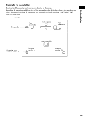
Install the IR transmitter and IR receiver of the surround speaker (L) in direct line with each other, and adjust the orientation of the surround speaker (L) Listening position Surround speaker (L) Surround speaker (R) 29US Top view IR transmitter Front speaker (L) Center speaker Front speaker (R) TV Subwoofer IR receiver of the IR transmitter and surround speaker (L) until the POWER/ON LINE indicator turns green. Getting Started Example for installation Position the IR transmitter and surround speaker (L) as illustrated.
Install the IR transmitter and IR receiver of the surround speaker (L) in direct line with each other, and adjust the orientation of the surround speaker (L) Listening position Surround speaker (L) Surround speaker (R) 29US Top view IR transmitter Front speaker (L) Center speaker Front speaker (R) TV Subwoofer IR receiver of the IR transmitter and surround speaker (L) until the POWER/ON LINE indicator turns green. Getting Started Example for installation Position the IR transmitter and surround speaker (L) as illustrated.
Operating Instructions
Page 30
... to install. when placing the surround speaker (L) toward the listening position, etc.), or when there is obstruction, such as a person or object between the IR transmitter and the IR receiver of the surround speaker (L), you connect the IR receiver to the surround speaker (L), the IR receiver is activated and the IR...
... to install. when placing the surround speaker (L) toward the listening position, etc.), or when there is obstruction, such as a person or object between the IR transmitter and the IR receiver of the surround speaker (L), you connect the IR receiver to the surround speaker (L), the IR receiver is activated and the IR...
Operating Instructions
Page 31
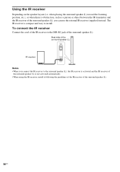
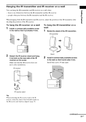
...4 mm. there is an obstruction between the IR transmitter and the IR receiver. IR receiver Stand 2 Install 2 commercially available screws in the wall so that both the IR transmitter and IR receiver, adjust the position of the IR transmitter. IR transmitter 4 mm 2 Detach the IR receiver stand and hang... it protrudes 4 mm. Getting Started Hanging the IR transmitter and IR receiver on a wall You can hang the IR transmitter and IR receiver on the screw. To hang the IR transmitter on the IR receiver and stand are aligned (page 15). 4 mm continued 31US...
...4 mm. there is an obstruction between the IR transmitter and the IR receiver. IR receiver Stand 2 Install 2 commercially available screws in the wall so that both the IR transmitter and IR receiver, adjust the position of the IR transmitter. IR transmitter 4 mm 2 Detach the IR receiver stand and hang... it protrudes 4 mm. Getting Started Hanging the IR transmitter and IR receiver on a wall You can hang the IR transmitter and IR receiver on the screw. To hang the IR transmitter on the IR receiver and stand are aligned (page 15). 4 mm continued 31US...
Operating Instructions
Page 32
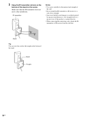
...move after installation. Stand Troughs 32US IR transmitter Notes • Use screws suitable for the material and strength of the wall. • Do not install the IR transmitter or IR receiver to a wall of the stand on the bottom of low strength. • Sony is not liable for any damage or ...accident incurred by incorrect installation (i.e. 3 Hang the IR transmitter via hole on the screw.
...move after installation. Stand Troughs 32US IR transmitter Notes • Use screws suitable for the material and strength of the wall. • Do not install the IR transmitter or IR receiver to a wall of the stand on the bottom of low strength. • Sony is not liable for any damage or ...accident incurred by incorrect installation (i.e. 3 Hang the IR transmitter via hole on the screw.
Operating Instructions
Page 95
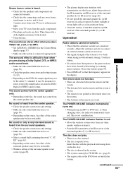
... the sound field function is on (page 59). • Check the speaker connections and settings (pages 35, 87). • Depending on the DVD, the output signal may come from the center speaker only. Use direct tuning. • No stations have been preset or the preset stations have ...are connected securely. • Check that the antennas (aerials) are connected securely. No sound is heard from any other nearby wireless system(s). • Point the IR transmitter at the remote sensor on the source, the effect of the surround speaker (L) (or IR receiver). The sound comes from the...
... the sound field function is on (page 59). • Check the speaker connections and settings (pages 35, 87). • Depending on the DVD, the output signal may come from the center speaker only. Use direct tuning. • No stations have been preset or the preset stations have ...are connected securely. • Check that the antennas (aerials) are connected securely. No sound is heard from any other nearby wireless system(s). • Point the IR transmitter at the remote sensor on the source, the effect of the surround speaker (L) (or IR receiver). The sound comes from the...
Service Manual
Page 1
... MODEL NAME SACD/DVD RECEIVER FRONT SPEAKER SURROUND SPEAKER CENTER SPEAKER SUB WOOFER DAV-FR10W HCD-FR10W SS-TS21 L SA-TS22W R SS-TS21 SS-CT33 SS-WS12 PARTS LIST Part No. DAV-FR10W SERVICE MANUAL Ver 1.0 2004.07 US Model Canadian Model • DAV-FR10W is composed of following... CORD, CONNECTION (VIDEO) CORD (WITH CONNECTOR) (SPEAKER) 2-108-866-11 MANUAL, INSTRUCTION (ENGLISH,FRENCH) A-1068-913-A DIR-T1 (TRANSMITTER) A-1070-387-A DIR-R2 (RECEIVER) 9-879-096-01 2004G16-1 © 2004.07 Sony Corporation Audio Group Published by Sony Engineering Corporation DVD HOME THEATRE SYSTEM
... MODEL NAME SACD/DVD RECEIVER FRONT SPEAKER SURROUND SPEAKER CENTER SPEAKER SUB WOOFER DAV-FR10W HCD-FR10W SS-TS21 L SA-TS22W R SS-TS21 SS-CT33 SS-WS12 PARTS LIST Part No. DAV-FR10W SERVICE MANUAL Ver 1.0 2004.07 US Model Canadian Model • DAV-FR10W is composed of following... CORD, CONNECTION (VIDEO) CORD (WITH CONNECTOR) (SPEAKER) 2-108-866-11 MANUAL, INSTRUCTION (ENGLISH,FRENCH) A-1068-913-A DIR-T1 (TRANSMITTER) A-1070-387-A DIR-R2 (RECEIVER) 9-879-096-01 2004G16-1 © 2004.07 Sony Corporation Audio Group Published by Sony Engineering Corporation DVD HOME THEATRE SYSTEM


